WEEK 4
EMBEDDED PROGRAMMING
Assignment :
Group assignment:
- Demonstrate and compare the toolchains and development workflows
for available embedded architectures.
Individual assignment:
- Browse through the data sheet for a microcontroller
- Write and test a program for an embedded system using a microcontroller
to interact (with local input &/or output devices)
and communicate (with remote wired or wireless connections)
* extra credit: try different languages &/or development environments
Group assignment:
During Week 4 (Embedded Programming), my teammate Carmen and the team organized ourselves to demonstrate and compare toolchains and development workflows across different microcontroller families. To divide the work, each member focused on one microcontroller. In my case, I documented the RP2040, and then shared my findings so we could compare them with the other architectures selected by the group.
To learn more, click here:
Group Assignment
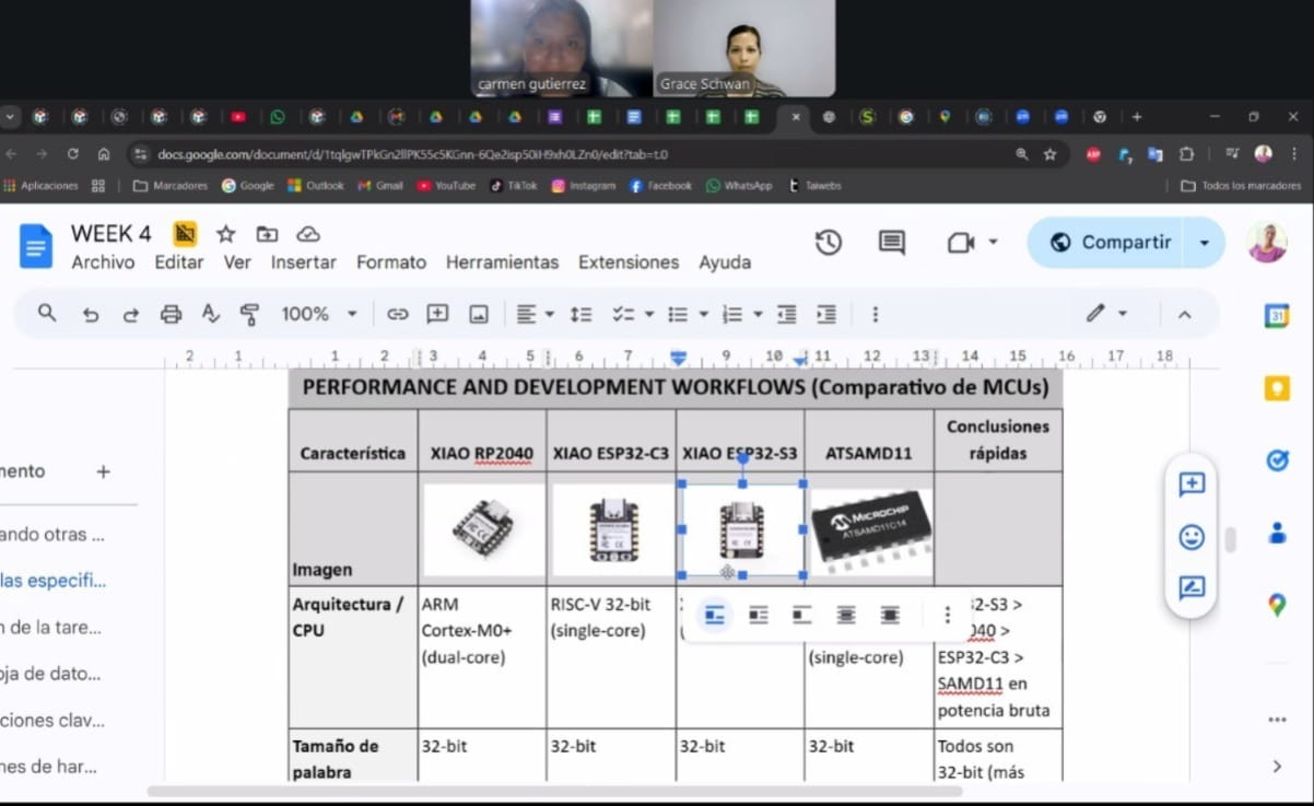
Compare performance and development workflows for other architectures
1) Comparing other architectures
For this comparison we used four different families (XIAO form factor + one “minimal” ARM option):
- RP2040 (ARM Cortex-M0+ dual-core, 32-bit)
- ESP32-C3 (RISC-V, 32-bit, Wi-Fi/BLE)
- ESP32-S3 (Xtensa LX7 dual-core, 32-bit, Wi-Fi/BLE)
- ATSAMD11 (sometimes written “ATAMD11”) (ARM Cortex-M0+, 32-bit)
Quick comparison of performance and capabilities (hardware)
| MCU/Board |
CPU / Architecture |
Max clock |
Memory (board/chip) |
Connectivity |
Typical use |
| RP2040 |
Dual-core ARM Cortex-M0+ |
133 MHz |
264 KB SRAM + 2 MB Flash |
No wireless |
Local control, PWM/ADC/PIO, fast prototyping |
| ESP32-C3 |
RISC-V 32-bit (single-core) |
160 MHz |
400 KB SRAM + 4 MB Flash |
Wi-Fi + BLE 5 |
Basic IoT, connectivity, low cost |
| ESP32-S3 |
Xtensa LX7 dual-core 32-bit |
240 MHz |
8 MB PSRAM + 8 MB Flash |
Wi-Fi + BLE 5 |
IoT + heavier apps / light edge-AI |
| ATSAMD11 |
ARM Cortex-M0+ 32-bit |
48 MHz |
16 KB Flash + 4 KB SRAM |
No wireless |
Minimalist, USB device, simple control, low power |
2. Analyze specifications and features:
This week we compared four microcontrollers/boards: RP2040, ESP32-C3, ESP32-S3, and ATSAMD11. The main differences between them are processing power, memory, connectivity, and the programming workflow they typically use.
Performance and development workflows (MCU comparison)
| Feature |
RP2040 |
ESP32-C3 |
ESP32-S3 |
ATSAMD11 |
Quick takeaways |
| Architecture / CPU |
ARM Cortex-M0+ (dual-core) |
RISC-V 32-bit (single-core) |
Xtensa LX7 (dual-core) |
ARM Cortex-M0+ (single-core) |
Raw compute: ESP32-S3 > RP2040 > ESP32-C3 > SAMD11 |
| Word size |
32-bit |
32-bit |
32-bit |
32-bit |
All are 32-bit (more capable than typical 8-bit MCUs) |
| Max clock |
Up to 133 MHz |
Up to 160 MHz |
Up to 240 MHz |
Up to 48 MHz |
S3 is fastest; SAMD11 is the most basic |
| Flash memory |
2 MB (on board) |
4 MB (on board) |
8 MB (on board) |
16 KB (on chip, typical) |
S3/C3 fit larger apps; SAMD11 requires tiny firmware |
| SRAM |
264 KB (on chip) |
~400 KB (on chip) |
SRAM + (external PSRAM) |
4 KB (on chip, typical) |
S3 stands out for total memory; SAMD11 is very limited |
| Extra memory |
— |
— |
8 MB PSRAM (on board) |
— |
S3 PSRAM helps with buffers, large libraries, and data |
| Connectivity |
No Wi-Fi/BLE (needs external module) |
Wi-Fi 2.4 GHz + BLE 5 |
Wi-Fi 2.4 GHz + BLE 5 |
No Wi-Fi/BLE |
For wireless communication: ESP32 (C3/S3) |
| Programming / Debug |
USB (UF2 bootloader), SWD pads |
USB/Serial (boot), JTAG/debug depends on board |
USB/Serial (boot), JTAG/debug depends on board |
SWD (Atmel-ICE/EDBG), bootloader depends on design |
SAMD11 is ideal to show SWD; RP2040 is very straightforward via USB |
| Common toolchains |
Arduino, MicroPython, CircuitPython |
Arduino, MicroPython, ESP-IDF |
Arduino, MicroPython, ESP-IDF |
Microchip Studio, ARM GCC, OpenOCD |
ESP-IDF shows a more “professional” flow (build/flash/monitor) |
| Typical workflow (summary) |
Plug in → upload sketch/UF2 → Serial/REPL |
Select port → flash → monitor → (Wi-Fi/BLE) |
Select port → flash → monitor → (Wi-Fi/BLE + more libs) |
Build → flash via SWD → debug |
Show at least 2 workflows (e.g., RP2040 USB vs SAMD11 SWD or ESP-IDF) |
| Best for… |
Local control, fast prototyping, PWM/ADC |
Simple IoT with Wi-Fi/BLE |
Advanced IoT, more memory, heavier apps |
Minimal projects, USB device, bare-metal |
Pick based on your demo goals (local vs wireless vs low-level) |
Simple explanation of each board
-
RP2040 is well balanced: it has dual-core, good speed (up to 133 MHz), and enough memory
(264 KB SRAM + 2 MB Flash) for medium projects. It’s ideal for local control (LEDs, buttons, sensors,
PWM, ADC) and quick development with Arduino or MicroPython.
-
ESP32-C3 is a good option when you need wireless connectivity, since it includes Wi-Fi and
Bluetooth (BLE). It is strong enough for basic IoT, and its main advantage is connecting to a network or a phone.
The workflow usually includes network setup (Wi-Fi credentials or BLE services).
-
ESP32-S3 is the most powerful: higher speed and much more memory available on the board
(large Flash + PSRAM). This helps when you need heavier tasks, larger libraries, or advanced features,
while still keeping Wi-Fi/BLE.
-
ATSAMD11 is the most basic and limited in resources (lower speed and memory). However, it is very useful for learning
because it pushes you to write efficient firmware and it is often programmed with a more “technical” workflow using ARM tools
and SWD debugging. It’s a good option to demonstrate a workflow different from “just upload via USB”.
Group assignment conclusion
In this group assignment we compared, through real practice, how these microcontrollers are programmed and how capable they are:
XIAO RP2040, XIAO ESP32-C3, XIAO ESP32-S3, and ATSAMD11.
We learned that it’s not only about how powerful a chip is, but also how easy it is to program, what tools it uses,
and how fast you can test changes.
In general, we found that:
- RP2040 is very comfortable for fast testing and local control (button/LED/sensors).
- ESP32 (C3/S3) is better when you need Wi-Fi or Bluetooth for IoT projects.
- SAMD11 helps you understand a more “technical” low-level workflow and debugging, although it has less memory and power.
In summary, teamwork helped us compare tools and workflows and choose the right microcontroller depending on the project requirements.
Group Work (Grace & Carmencita)
Carmencita and I worked together on the group assignment, testing and comparing two embedded development
workflows using real hardware (XIAO RP2040 and XIAO ESP32-C3). We documented our process, troubleshooting,
and results as a team.
For more details, please visit our group documentation:
🔗 View Group Documentation
Carmencita’s Week 4 documentation:
View Carmencita’s page
Individual assignment
Explore the datasheet for the RP2040 microcontroller
RP2040 microcontroller
I chose to study the microcontroller RP2040 because it combines an ultra-compact form factor with good performance for prototyping and embedded systems. It is ideal for portable projects and for testing different programming environments (Arduino/MicroPython/CircuitPython).
🔹 RP2040 Microcontroller Features
General Information
- Manufacturer: Raspberry Pi
- Model: RP2040
- Architecture: Dual-core ARM Cortex-M0+ (32-bit)
- Maximum clock frequency: Up to 133 MHz
Memory
- Internal SRAM: 264 KB
- Internal Flash: ❌ None
- External memory support: QSPI interface for external Flash (required to store the program)
GPIO (Input/Output)
- Up to 30 multifunction GPIO pins
- Logic level: 3.3 V
- Configurable as digital input or output
- Interrupt support
Analog-to-Digital Conversion
- 12-bit ADC
- 5 ADC channels:
- 4 external analog inputs
- 1 internal temperature sensor
Communication
- 2 × UART
- 2 × I2C
- 2 × SPI
- USB 1.1 controller (Device or Host with external PHY)
PWM
- 8 PWM slices
- 16 PWM channels total
DMA
- 12 DMA channels for direct memory transfers
Timers
- Hardware timers
- Watchdog timer
Special Feature — PIO (Programmable I/O)
- 2 PIO blocks
- 4 state machines per block (8 total)
- Enables custom hardware protocols (e.g., WS2812, proprietary protocols, special signals)
Electrical Characteristics
- Core voltage: 1.1 V (internally regulated)
- I/O voltage: 3.3 V
- Not 5 V tolerant on GPIO pins
- Low power consumption
Package
.png)
Hardware precautions (important)
- 3.3 V GPIO: do not apply signals above 3.3 V to the I/O pins to avoid damage.
- Power supply: it can be powered with 5 V through power pins (regulated internally to 3.3 V).
- Battery + USB-C: avoid connecting USB-C while a battery is connected (safety risk).
Pin map (useful functional summary)
- Analog (ADC): D0=P26, D1=P27, D2=P28, D3=P29.
- I2C: D4=SDA (P6), D5=SCL (P7).
- UART: D6=TX (P0), D7=RX (P1).
- SPI: D8=SCK (P2), D9=MISO (P4), D10=MOSI (P3).
- Control: BOOT (bootloader mode) and RESET (restart).
.png)
Bootloader and port recovery (when it “disappears”)
- Hold the BOOT (B) button.
- Connect the RP2040 to the computer.
- The device appears as a drive (bootloader mode) and the programming port becomes available again.
Note about the onboard LED
- The onboard RGB LED behavior can be inverted compared to Arduino (in some cases it turns on with LOW).
Learnings - Exploring the XIAO RP2040 datasheet
-
I learned how to quickly extract “what matters” from a datasheet: CPU architecture, clock, memory, voltage levels,
and available peripherals (ADC, PWM, UART, I2C, SPI). This helped me decide what the board can realistically do for my demo.
-
I understood why the 3.3 V logic level is critical. Even if the board can be powered with 5 V (because it regulates internally),
the GPIO pins still operate at 3.3 V, so applying higher voltage to inputs can damage the microcontroller.
-
I learned to read a pin mapping not only by board labels (D0, D1, etc.) but also by the MCU pin names (P26, P27…).
This is important when using different libraries or when debugging wiring mistakes.
-
I clarified the difference between power pins vs. signal pins: power can enter through specific pins (with internal regulation),
but signals must respect the logic voltage. This avoids common beginner errors when connecting sensors or modules.
-
I discovered how the BOOT/RESET workflow works on RP2040 boards. If the programming port “disappears” after a failed upload,
holding BOOT while connecting forces bootloader mode, and the board shows up again as a storage device (UF2), making recovery easy.
-
I learned that the onboard RGB LED behavior can be inverted compared to Arduino expectations (sometimes LOW turns it on).
This is important when testing “blink” or status indicators, so I don’t misinterpret results.
-
I realized the RP2040 is a very good choice for fast prototyping because it supports multiple environments
(Arduino/MicroPython/CircuitPython). This lets me test the same hardware with different toolchains and compare workflows.
Individual assignment — Programming RP2040
Programming process (simple)
- Software: I used Arduino IDE on Windows with the RP2040 board support.
- Connection: I plugged my board into the computer using a USB-C data cable.
- Upload steps: I entered BOOT mode (RPI-RP2) → clicked Upload in Arduino → the board restarted and ran the program.
- Local input: a pushbutton starts the LED sequence.
- Local output: three LEDs blink following a pattern.
- Communication: I used the Serial Monitor to see messages and confirm the button press and cycles.
What I changed (modified code)
- Replaced
delay() with a non-blocking timing approach using millis().
- Used
INPUT_PULLUP + debounce for a more stable button reading.
- Triggered the sequence only once per press (press-event), instead of repeating continuously.
- Organized the LEDs using an array to keep the code cleaner and easier to scale.
Wiring (pins used)
- LEDs: D0, D6, D7 (each LED with a resistor to GND).
- Button: D1 connected to GND (using
INPUT_PULLUP).
Source code (Arduino — modified version)
Show/hide source code — Button debounce + LED sequence (millis)
// Week 4 - XIAO RP2040
// Modified version: stable button (INPUT_PULLUP), press-event trigger, no delay (millis), LED array

const uint8_t LEDS[] = {D0, D6, D7};
const uint8_t NLEDS = sizeof(LEDS) / sizeof(LEDS[0]);

const uint8_t BUTTON_PIN = D1;          // button to GND
const unsigned long STEP_MS = 250;      // speed of the animation
const int CYCLES_TO_RUN = 7;            // how many times the pattern repeats

// Debounce
int lastReading = HIGH;
int stableState = HIGH;
unsigned long lastDebounceTime = 0;
const unsigned long DEBOUNCE_MS = 30;

// Sequence state machine
bool running = false;
int cycleCount = 0;
int stepIndex = 0;                      // 0..(2*NLEDS - 1)
unsigned long lastStepTime = 0;

void allOff() {
  for (uint8_t i = 0; i < NLEDS; i++) digitalWrite(LEDS[i], LOW);
}

void setup() {
  Serial.begin(9600);

  for (uint8_t i = 0; i < NLEDS; i++) pinMode(LEDS[i], OUTPUT);
  pinMode(BUTTON_PIN, INPUT_PULLUP);   // more stable

  allOff();
  Serial.println("RP2040 ready. Press the button to run the LED sequence.");
}

void startSequence() {
  running = true;
  cycleCount = 0;
  stepIndex = 0;
  lastStepTime = millis();
  allOff();
  Serial.println("Button pressed -> starting sequence");
}

void updateSequence() {
  if (!running) return;

  unsigned long now = millis();
  if (now - lastStepTime < STEP_MS) return;
  lastStepTime = now;

  // Pattern: turn ON LEDs forward, then turn OFF LEDs backward
  if (stepIndex < NLEDS) {
    digitalWrite(LEDS[stepIndex], HIGH);
  } else {
    int offIdx = (2 * NLEDS - 1) - stepIndex;
    digitalWrite(LEDS[offIdx], LOW);
  }

  stepIndex++;

  // End of one full cycle
  if (stepIndex >= 2 * NLEDS) {
    stepIndex = 0;
    cycleCount++;
    Serial.print("Cycle: ");
    Serial.println(cycleCount);

    if (cycleCount >= CYCLES_TO_RUN) {
      running = false;
      allOff();
      Serial.println("Sequence finished.");
    }
  }
}

void loop() {
  // ----- Debounced button reading -----
  int reading = digitalRead(BUTTON_PIN);

  if (reading != lastReading) {
    lastDebounceTime = millis();
    lastReading = reading;
  }

  if (millis() - lastDebounceTime > DEBOUNCE_MS) {
    if (reading != stableState) {
      stableState = reading;

      // Press event (INPUT_PULLUP => pressed = LOW)
      if (stableState == LOW) {
        if (!running) startSequence();
        else Serial.println("Sequence already running...");
      }
    }
  }

  // ----- Run the LED animation without blocking -----
  updateSequence();
}
1) Code 1 — Debounced button + LED sequence (millis)
This program for the XIAO RP2040 uses three LEDs (D0, D6, D7) and a pushbutton (D1 to GND).
The button is configured with INPUT_PULLUP and debounced to avoid false triggers.
When a valid press event is detected, it starts a non-blocking LED animation using millis()
(no delay()): LEDs turn ON forward and then turn OFF backward, repeating for a set number of cycles.
Serial messages are printed to confirm button press, cycle count, and when the sequence finishes.
⬇️ Download Code 1 (.ino)
Credits / Acknowledgements
-
PCB / Programmer board: I used a board created by Adrian Torres called QUENTORRES.
I downloaded the PCB PNG files from the official repository.
Full documentation is available here:
QUENTORRES documentation (Fabcloud GitLab)
.
-
Code reference: I used as a starting example a sketch shared by Ronal Vilca on his Fab Academy page:
Ronal Vilca — Week 6
.
I then made my own variation (timing logic, button handling, and LED sequence changes) so the final code is unique and fully understood by me.
Difficulties / Challenges
-
At the beginning I got confused because the RPI-RP2 drive disappears after uploading.
Later I understood this is normal: the board resets and runs the program, so it leaves BOOT mode.
-
Sometimes the board did not show a COM port in Arduino IDE.
I solved it by using a real USB-C data cable (not charge-only) and reconnecting the board.
-
I had issues with the pushbutton reading: it was unstable at first.
I fixed it by using INPUT_PULLUP and understanding that pressed = LOW.
-
The LED sequence was repeating too much when I kept the button pressed.
I solved it by triggering the sequence only once per press (press-event logic).
-
Using
delay() made the program feel “stuck” and less responsive.
I changed it to millis() to make the code non-blocking.
-
I also had to double-check my wiring (pins, GND, resistors) because small mistakes easily stop the LEDs from working.
How I tested it
- Connected the board to my Windows PC using a USB-C data cable.
- In Arduino IDE, selected Seeed XIAO RP2040 and the correct COM port.
- Uploaded the sketch. (If needed: entered BOOT mode to restore the device and re-upload.)
- Opened Serial Monitor at 9600 baud to verify button press logs and cycle count.
- Pressed the button and confirmed the LED pattern ran once per press.
Evidence to include:
- Hero shot: board + wiring + LEDs + button.
- Screenshot of Arduino IDE showing successful upload.
- Short video: press button → LEDs run sequence → serial messages.
- Source code embedded as text (this page) or downloadable file.
Media (photos + video)
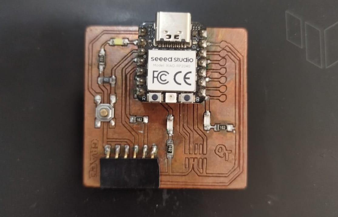 Hero shot — XIAO RP2040 with button and 3 LEDs.
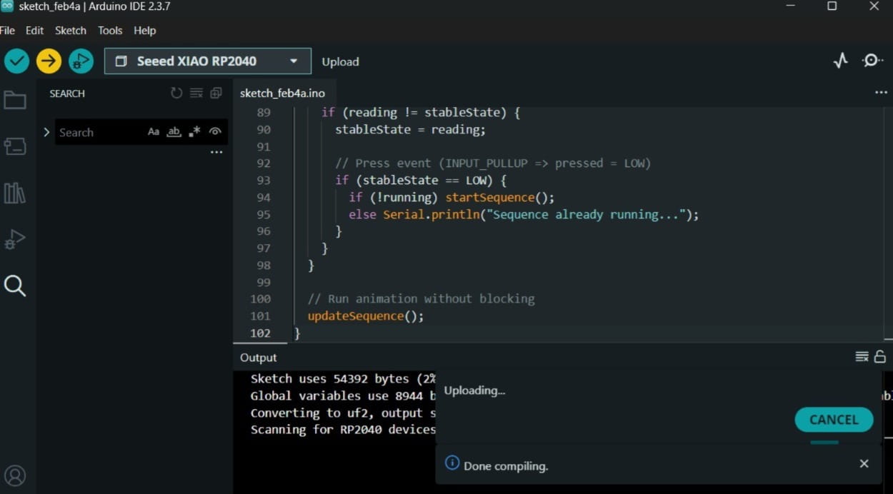
Problem:Arduino IDE upload screenshot (“Done uploading”).
Learnings - Programming the RP2040
-
Now I understand how uploading works on the RP2040 in Windows: I enter BOOT mode
(it shows up as RPI-RP2), upload from Arduino IDE, and then the drive disappears because the board
resets to run the code — so that’s totally normal.
-
I got the full workflow clear: select the right board, pick the correct COM port,
upload the sketch, and check everything using the Serial Monitor.
-
I learned the difference between interaction and communication:
the button is my input, the LEDs are my output, and Serial is how I “see” what’s happening
(wired communication to the PC).
-
I learned why INPUT_PULLUP is better: the button reading becomes stable (no random values).
The only thing is the logic changes: pressed = LOW.
-
I added debounce, which basically prevents multiple triggers from a single press.
-
I replaced
delay() with millis(), so my code is not “blocked” anymore.
It feels more professional and easier to expand.
-
Using an array for LED pins made the code cleaner and easier to scale.
-
And most importantly: I used a reference code, but I modified it (timing, button handling, LED sequence),
I gave credit, and now the final code is unique and fully understood by me.
Communication demo — Serial ( RP2040 ↔ PC)
Source Code (XIAO RP2040)
Show/hide code — Button + LED sequence + Serial commands
// XIAO RP2040 - Week 4 (Fab Academy)
// Interaction: Button starts LED sequence (input)
// Output: 3 LEDs blink in a pattern (output)
// Communication: USB Serial PC <-> XIAO (commands + logs)
//
// Pins used (change if needed):
// LEDs: D0, D6, D7
// Button: D1 to GND (INPUT_PULLUP)

const uint8_t LEDS[] = {D0, D6, D7};
const uint8_t NLEDS = sizeof(LEDS) / sizeof(LEDS[0]);
const uint8_t BUTTON_PIN = D1;          // button to GND

// Sequence parameters
bool running = false;
int cyclesToRun = 7;
int cycleCount = 0;
int stepIndex = 0;                       // 0..(2*NLEDS-1)
unsigned long lastStep = 0;
unsigned long stepMs = 250;              // animation speed

// Button debounce / press-event
int lastReading = HIGH;
int stableState = HIGH;
unsigned long lastDebounceTime = 0;
const unsigned long DEBOUNCE_MS = 30;

// ---------- helpers ----------
void allOff() {
  for (uint8_t i = 0; i < NLEDS; i++) digitalWrite(LEDS[i], LOW);
}

void allOn() {
  for (uint8_t i = 0; i < NLEDS; i++) digitalWrite(LEDS[i], HIGH);
}

// ---------- sequence ----------
void startSequence() {
  running = true;
  cycleCount = 0;
  stepIndex = 0;
  lastStep = millis();
  allOff();
  Serial.println("Button pressed -> sequence start");
}

void updateSequence() {
  if (!running) return;

  unsigned long now = millis();
  if (now - lastStep < stepMs) return;
  lastStep = now;

  // Pattern: turn ON LEDs forward, then turn OFF LEDs backward
  if (stepIndex < NLEDS) {
    digitalWrite(LEDS[stepIndex], HIGH);
  } else {
    int offIdx = (2 * NLEDS - 1) - stepIndex;
    digitalWrite(LEDS[offIdx], LOW);
  }

  stepIndex++;

  // End of one full cycle
  if (stepIndex >= 2 * NLEDS) {
    stepIndex = 0;
    cycleCount++;
    Serial.print("Cycle: ");
    Serial.println(cycleCount);

    if (cycleCount >= cyclesToRun) {
      running = false;
      allOff();
      Serial.println("Sequence finished.");
    }
  }
}

// ---------- serial commands ----------
void handleCommand(String s) {
  Serial.print("RX: ");
  Serial.println(s);

  s.trim();
  s.toLowerCase();

  if (s == "on") {
    running = false;
    allOn();
    Serial.println("OK: LEDs ON");
    return;
  }

  if (s == "off") {
    running = false;
    allOff();
    Serial.println("OK: LEDs OFF");
    return;
  }

  if (s == "start") {
    if (!running) startSequence();
    Serial.println("OK: start");
    return;
  }

  if (s == "status") {
    Serial.print("running=");
    Serial.print(running ? "true" : "false");
    Serial.print(" stepMs=");
    Serial.print(stepMs);
    Serial.print(" cyclesToRun=");
    Serial.println(cyclesToRun);
    return;
  }

  if (s.startsWith("blink ")) {
    int v = s.substring(6).toInt();
    if (v < 50) v = 50;
    stepMs = (unsigned long)v;
    Serial.print("OK: stepMs=");
    Serial.println(stepMs);
    return;
  }

  Serial.println("ERR: try: on | off | start | status | blink 300");
}

// ---------- setup / loop ----------
void setup() {
  Serial.begin(115200);
  delay(1200);

  for (uint8_t i = 0; i < NLEDS; i++) pinMode(LEDS[i], OUTPUT);
  pinMode(BUTTON_PIN, INPUT_PULLUP);

  allOff();

  Serial.println("XIAO RP2040 ready.");
  Serial.println("Commands: on | off | start | status | blink ");
  Serial.println("Press the button to start the LED sequence.");
}

void loop() {
  int reading = digitalRead(BUTTON_PIN);

  if (reading != lastReading) {
    lastDebounceTime = millis();
    lastReading = reading;
  }

  if (millis() - lastDebounceTime > DEBOUNCE_MS) {
    if (reading != stableState) {
      stableState = reading;

      if (stableState == LOW) {
        if (!running) startSequence();
        else Serial.println("Sequence already running...");
      }
    }
  }

  if (Serial.available()) {
    String line = Serial.readStringUntil('\n');
    line.trim();
    if (line.length() > 0) handleCommand(line);
  }

  updateSequence();
}
2) Code 2 — Button + LED sequence + Serial Monitor commands
This program is an extended version of Code 1. It keeps the same local interaction: a debounced button
(D1 to GND) triggers a non-blocking LED sequence on three LEDs (D0, D6, D7) using millis().
Additionally, it implements USB Serial communication: you can send text commands from the Serial Monitor
to control the LEDs and read status. Commands include on, off, start,
status, and blink <ms> to change the animation speed in real time.
This demonstrates both local interaction and communication (PC ↔ board) in the same embedded system.
⬇️ Download Code 2 (.ino)
What “serial communication” means in my project
- Wired communication via USB: the XIAO RP2040 creates a virtual COM port on Windows.
- XIAO → PC: logs using
Serial.println() (status, cycles, OK messages).
- PC → XIAO: I send commands from Arduino Serial Monitor (example:
on, off, blink 150, status).
Tools and what I needed
- Software: Arduino IDE (Windows) + Seeed XIAO RP2040 board support
- Hardware: my custom PCB with XIAO RP2040 + USB-C data cable
Step-by-step workflow (how I tested serial)
- Connected the board to my PC using a USB-C data cable.
- In Arduino IDE, selected Board: Seeed XIAO RP2040.
- Selected the correct COM port (example: COM4).
- Uploaded the sketch.
- Opened Serial Monitor and set 115200 baud (must match
Serial.begin(115200)).
- Set line ending to New Line and typed commands to verify two-way communication.
Commands I used (PC → XIAO)
on → turn all LEDs ONoff → turn all LEDs OFFblink 150 → change animation speedstatus → print current settings
Evidence (XIAO → PC)
The board replies back in Serial Monitor with messages like:
RX: on, OK: LEDs ON, and cycle counters.
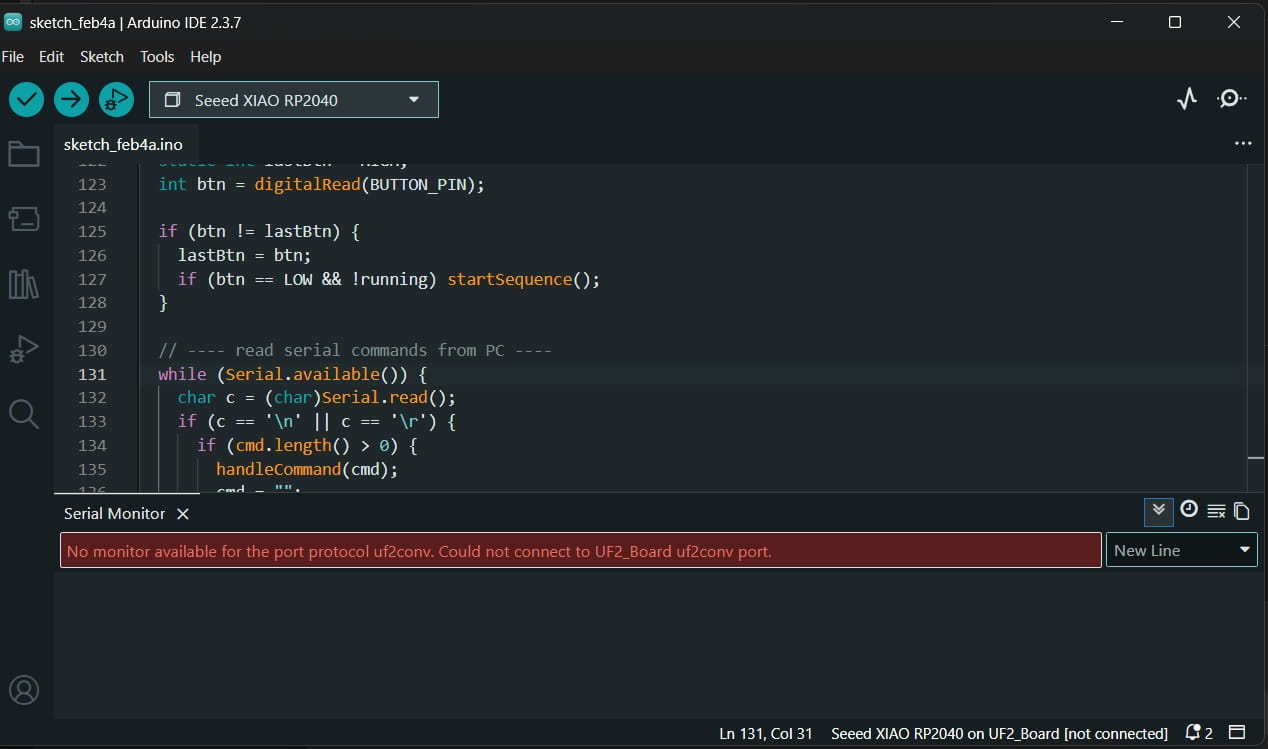
Problem: Serial Monitor failed because I was on UF2_Board (bootloader), not a COM port.
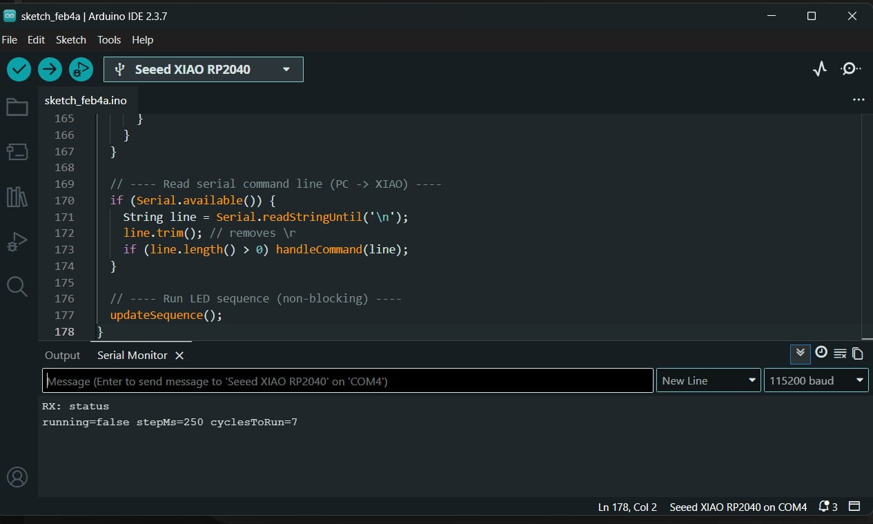
Fixed: After selecting the real COM port, Serial Monitor showed RX/OK responses.
Difficulties (real mistakes + how I fixed them)
-
UF2_Board error: I tried to open Serial Monitor while the board was in UF2/boot mode.
Fix: I selected the real COM port instead of UF2_Board.
-
No text in Serial Monitor: my baud rate didn’t match the code.
Fix: I set 115200 in Serial Monitor to match Serial.begin(115200).
-
RPI-RP2 disk disappeared: I thought the board was broken.
Fix: I learned it’s normal — after upload the board exits BOOT mode and runs the sketch.
-
Commands didn’t respond at first: line ending was wrong.
Fix: I used New Line and pressed Enter to send the command properly.
Learnings — Serial communication (RP2040 ↔ PC)
- I learned that the RP2040 has two modes on Windows: BOOT mode (RPI-RP2 / UF2) for uploading, and normal mode (COM port) for Serial Monitor.
- I learned that UF2_Board is not a Serial port. Serial Monitor works only with the real COM port (e.g., COM4).
- I learned that the baud rate must match the code. If the sketch uses
Serial.begin(115200), Serial Monitor must be set to 115200.
- I learned how to prove real communication with two-way serial: PC sends commands (
on, off, blink 150) and the board replies (OK: LEDs ON).
- I learned that the line ending matters. Using New Line (or Both NL & CR) helps the board read commands correctly.
- I learned that if Serial Monitor looks empty, pressing RESET can print the startup messages again.
- I learned a simple troubleshooting checklist: data cable, correct port, correct baud, and correct line ending.
Conclusions
Group Conclusions (RP2040 vs ESP32-C3)
- Programming two different microcontroller families allowed us to understand that the development workflow depends not only on the code, but also on correct environment configuration (board selection, drivers, and COM port management).
- The ESP32-C3 required more attention to setup details, especially using GPIO numbers instead of Arduino-style D pins and correctly selecting the COM port. This showed that many initial errors were related to the toolchain rather than the program logic.
- The RP2040 provided a more straightforward workflow for local hardware prototyping (button and LEDs), making debugging simpler and faster.
- As a team, we reinforced a structured debugging methodology: verify wiring → select correct board and port → compile → upload → validate using LED behavior and Serial Monitor.
Individual Conclusions (XIAO RP2040)
- A stable hardware-software interaction was implemented using a pushbutton with
INPUT_PULLUP and software debounce, preventing false triggering caused by mechanical bounce.
- The LED sequence was controlled using a non-blocking timing approach with
millis(), demonstrating better embedded programming practice compared to using delay().
- The original code provided by Ronal Vilca was improved and reorganized to enhance stability and structure.
- ChatGPT was used as a support tool to help analyze, refactor, and optimize the code (debounce logic, non-blocking timing, and serial structure). The final implementation was tested, modified, and validated on the physical hardware.
- Real troubleshooting (pin configuration, wiring adjustments, and debugging through Serial Monitor) strengthened practical understanding of embedded system development.
AI assistance (code adaptation)
I started from Ronal Vilca’s original sketch and used ChatGPT as a support tool to adapt and improve it
for my own wiring and testing on the XIAO RP2040.
Show/hide — Prompt used to adapt Ronal Vilca’s code
Help me modify Ronal Vilca’s Arduino code for the XIAO RP2040 so it works with my wiring.
I need a stable button input using INPUT_PULLUP + debounce, trigger the LED sequence only once per press,
replace delay() with millis(), and keep Serial messages for debugging and validation.
Show/hide — What I changed (my modifications)
- Updated pin mapping to match my setup (LEDs on D0, D6, D7; button on D1 to GND).
- Configured the button with
INPUT_PULLUP and added software debounce to avoid false triggers.
- Implemented a press-event trigger so the sequence runs once per button press.
- Replaced
delay() with a non-blocking timing approach using millis().
- Added Serial prints to confirm events, cycles, and system state during testing.
Assessment checklist
- ✅ Linked to the group assignment page (verify the button link is not “GROUP_PAGE_LINK_HERE”)
- ✅ Browsed and documented some information from a microcontroller’s datasheet (RP2040)
- ✅ Programmed a board to interact and communicate (button + LEDs + Serial)
- ✅ Described the programming process(es) used (toolchain, BOOT, upload, Serial monitor)
- ✅ Included source code (embedded + downloadable .ino)
- ✅ Included hero shot(s) (board + wiring visible)