12. Output devices
The goal for this week is to actuate a device using a microcontroller. The closest I have ever done is turning on an LED in the previous weeks of the Fab Academy, so I am really eager to move a motor. For what I have read, Pulse Width Modulation is what will allow us to accurate move this devices.
As usual, at the begining of the week, I would like to build a board for every type of motor Neil talked about in the recitation... But I have to be realistic, I know it will be a great success if I can actuate any of them. I will start with a bipolar stepper, then a DC motor, and finally, if I have time, a brushless DC motor.
Bipolar stepper motor
Before I did anything, I read through this article by tech explorations, explaining the difference between unipolar and bipolar stepper motors. I understood that bipolar have a simple winding per phase, whereas unipolar operates with one winding with a center tap per phase, so each section of the winding is switched on for each direction of the magnetic field. So unipolar motors are a bit more complex to build but electronics to control them is simpler, since there is no need to switch the direction of the current. Bipolar motors are simpler to make and are more efficient. They need reverse current, so the magnetic pole position can be reversed: this is done with two H-bridges, one per phase coil.
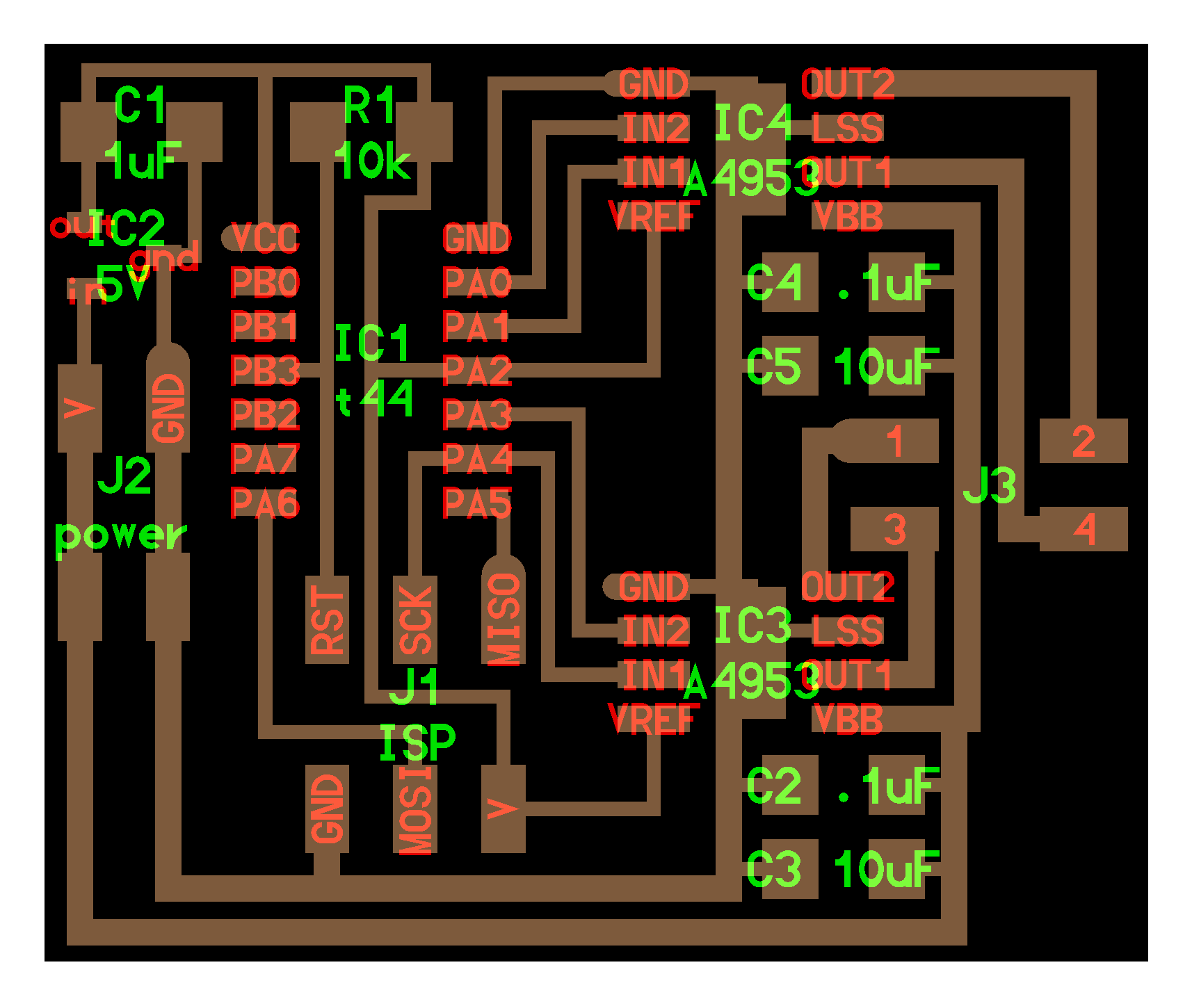
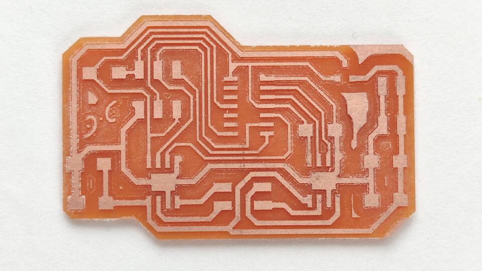
I used as the starting point, Neil's hello stepper bipolar 44 board. First thing was analize the footprint. I noticed, as Neil had pointed out, the wider traces on the motor side of the board. I also noticed that it was somehow like a board for operating two DC motors. Then I thougth it makes sense, since there are two coils, one per phase.
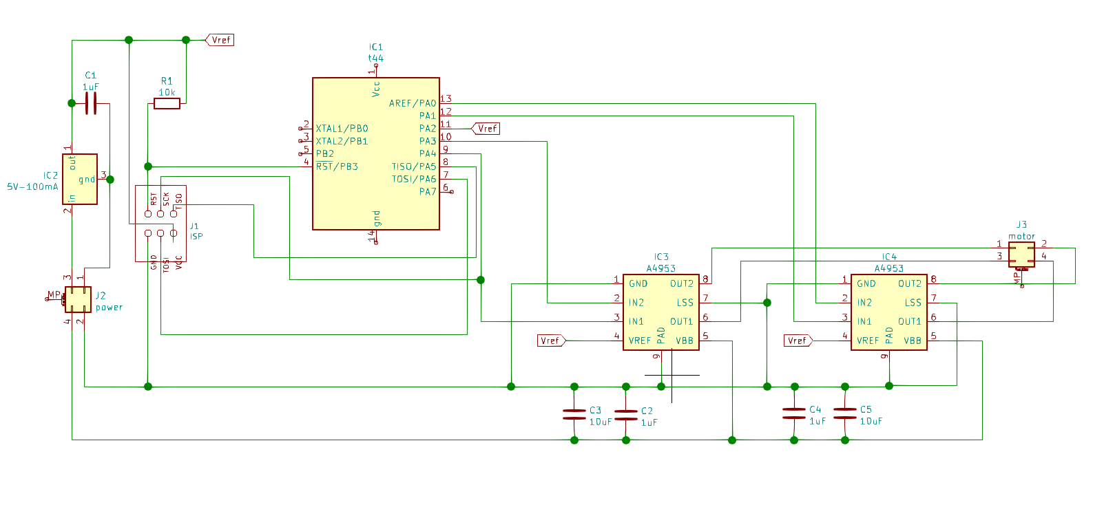
I drew the schematic using Kicad. For the first time, I edited symbols from the Library, just changing a few names, such as MISO and MOSI for TISO and TOSI. I also followed the same naming convention Neil used in his board.
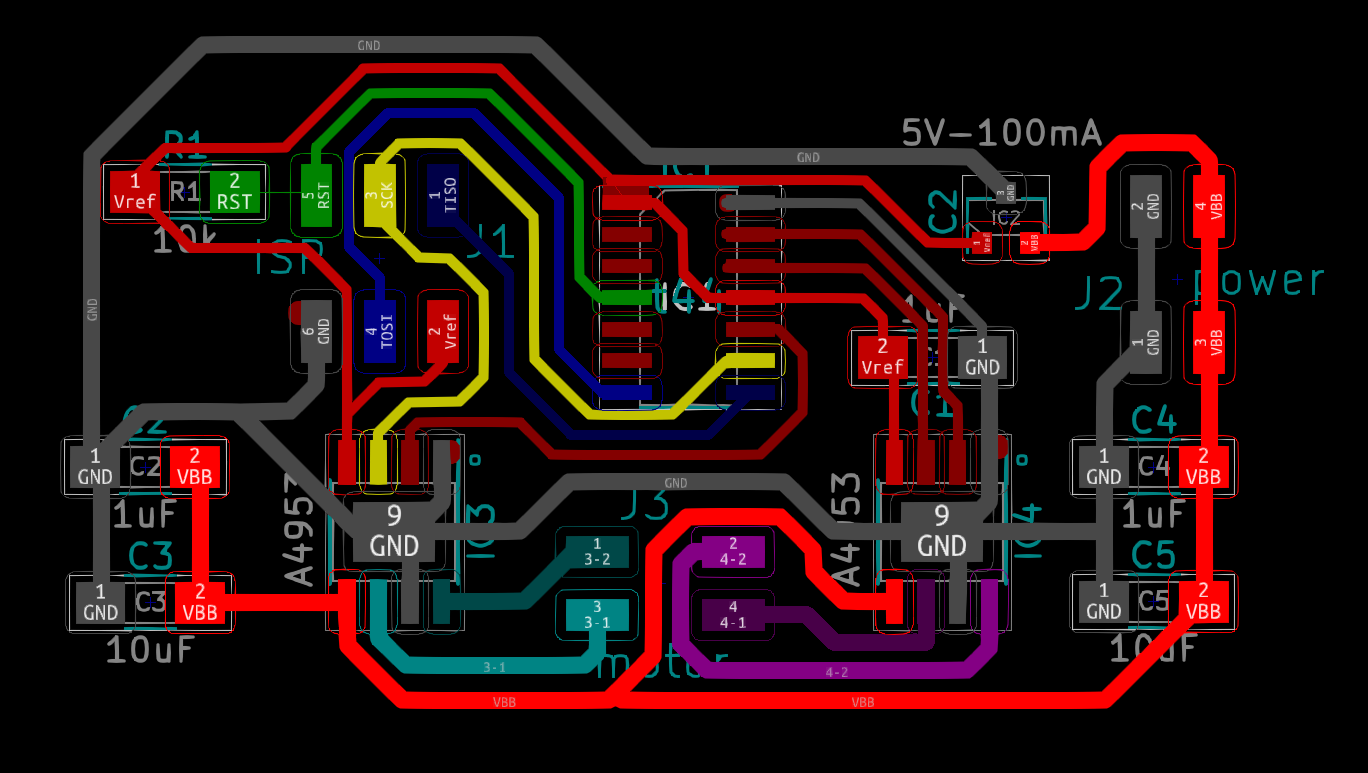
After the schematic was done, I swithed to the PCB board editor, and solved the sudoku. I have to admit that I really like this part of the job, it is challenging to solve it, and I find kind of beautiful how the lines flow to find an escape.
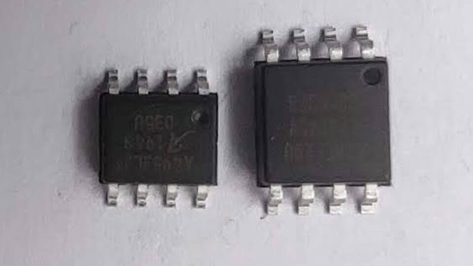
Also, as I noticed last week, I confirmed that the footprint for the AT Tiny 45 was the same SOIC 8 that the one for the motor driver, A4953, but when I compared them, the driver is clearly smaller. Then I downloaded the footprint of the t45, from Microchip website, and found out that the footprint used for it as larger, measuring 8.8 mm in width, that is, 1.4 mm more than that. So I made a copy in the library for the t45 and modified it acordingly. Then went on to post an issue on Gitlab, and somebody ran into the same problem last week, so I posted the new library item.
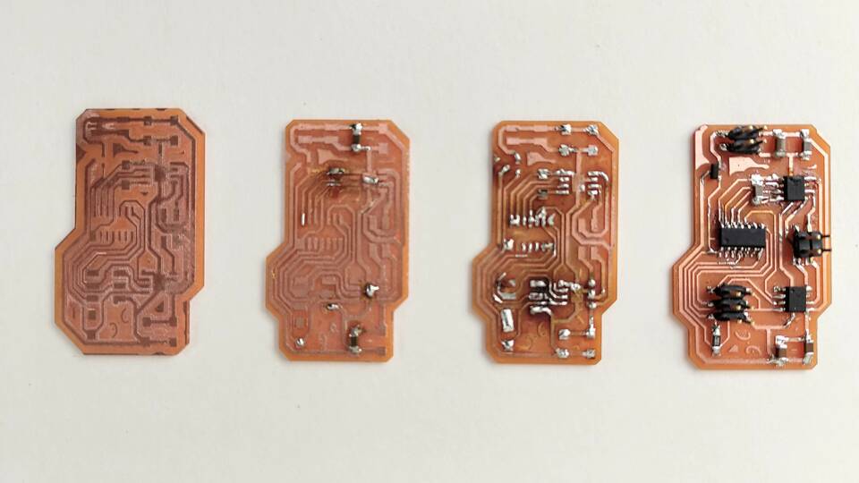
Next step is to mill the board. I used the same workflow as in previous weeks, for now I am still sticking to mods CBA edition... as soon as I learn more about it, I will modify the CE edition, to fit my machine's defaults. I used 6 mm/sec, 18k, 0.1 mm depth cut for the traces, and 6 mm/sec, 18k, 0.25 mm depth cut for the outline. The first board milled had some cooper unremoved in two areas, so I repeated them, but increasing the depth for the traces to 0.15 mm.
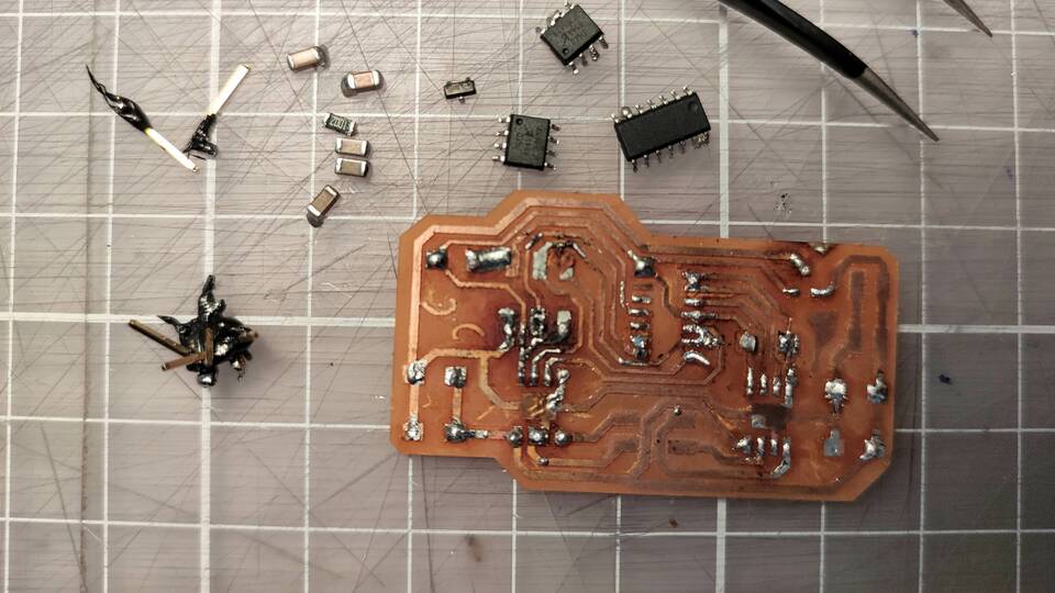
Soldering was going much better this time over, I was concerned about the A4953 drivers being smaller and with the same pin count as the t45, but it worked just fine. I even fixed a missing conection between RST and a 10k resistor, with a little strip of copper... until I came across the ISP header, and somehow I burnt the Vcc trace, and trying to fixit, the plastic in the header melted and messed everything up. At least, I recovered all the components by unsoldering hith hot air. Anyway, I know that I have to keep working on my soldering...
Back to Kicad, and I am thinking that maybe it is worth it to move components a bit farther away, so there is more room between traces.
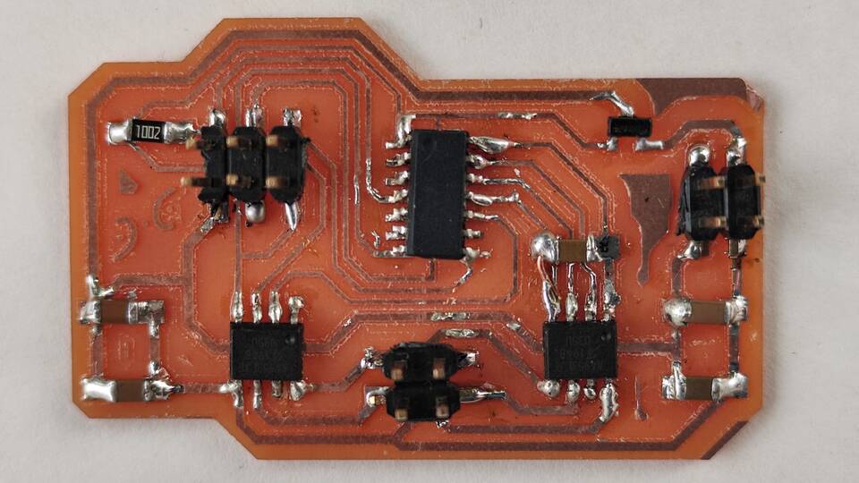
This time I thought it was goign to be easy... but I was also struggling soldering both A4953 and the AT Tiny 44. It was taking quite a while for the solder to melt, so I tried raising the temperature up to 400C. Then, my instructors told me that that was waaaay to high, that I should be working at about 320C, and that the problem could either be the quality of the soldering wire or the dirt in the tip of my soldering iron. So I cleaned it the best I could, and tested other soldering wire. This time it worked!!! within one second, the solder would melt. So this time I did not mess the ISP header up!!!
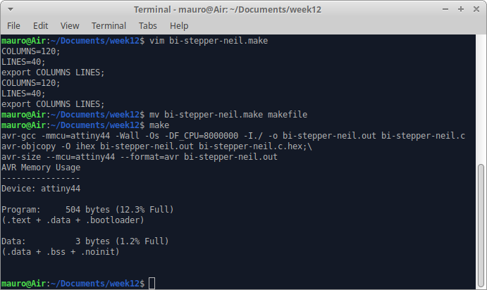
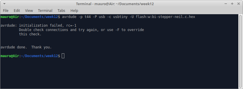
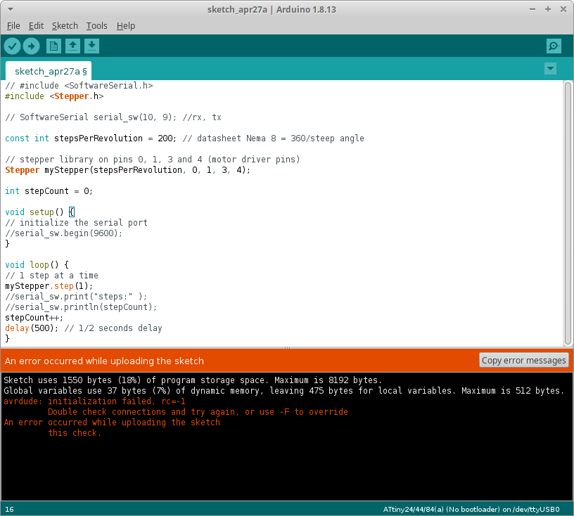
To load a program, I tried two approaches: first, Neil's program and makefile, then Elena's, with the Ardunino IDE. In both, I got errors, avrdude: initialization failed, rc=-1. Before that, the makefile succesfully compiled Neils program into C. I followed this tutorial, and even at first it appeared that there were missing steps, I could figure all out. I then used the following command to upload it: avrdude -p t44 -P usb -c usbtiny -U flash:w:bi-stepper-neil.c.hex. And I got the beforementioned error.
The first debugging step was to check again schematic and PCB traces, but I did not find anything wrong there. Then, I rechecked continuity betweeen pins, and also everything seemed fine. I did not know if the problem was the new board or the fabISP, so I went back to the board I made with an LED and a button, and uploaded two different programs which worked fine. So probably the problem is in my new board. I contacted Adrian, who helped me debugging. Next, I checked continuity between pins, which were ok. Then, voltage in both sides of the voltage regulator, that were also fine. Since the t44 is a reused part from the board I desoldered, Adrian told me that I might have damaged the microcontroller, and sugested me to desolder it and place a new one
Surprisingly, this time it was easier to desolder. I also removed lots of solder that I had in the pads, and placed a new microcontroller. Then, at last, I finally loaded the code into the board!!! At first, the motor just shaked, but there was current flowing through the circuit. I swchiched polarity of the coils, and finally got the stepper spinning!!!
Unfortunanetly, the movement was not as smooth as it should. At first I thought that the 9V battery was not enough to drive the motor, so I used a 12V DC power supply from an old device. The problem persisted: so next I started checking currents. I got a reading of 15mA for the whole board. But then, accidentally hit the wrong trace with the tip of the polymeter, and some smoke came out from the board. It was still working (in its funny way, of course), so I changed to check voltages, and found out that the voltage regulator was no longer working. The t44 was getting quite hot, so I swiched power off.
Reviewing Elena's assignment, she had similar problems, which she solved: in her case it was just on pin on one of the drivers that had a cold solder joint. Honestly, her soldering looks much better than mine, so probably the problem is there... I really want to make this work, so even though I only have a couple of hours before the review, I am heading to the lab to mill the fith PCB.
As my classmate Lorena pointed out, I also have an Elephants' Graveyard... that will remind me how easy is to fail in any moment of the journey, and that no matter how bad things might seem, we can always work oru way ahead.
This week I have mixed feelings: on one hand I am not happy that, again, I did not successfully fulfilled the assignment; on the other, I am really happy that I got a big portion of it done, and I finally catched up uploading programs onto the board, both directly with avrdude and through the Arduino IDE. I know that I have little time left in this cycle, and I really need to improve my soldering skills. I am also aware that debugging is not easy, and I am many times lost deciding which of my actions will have the best outcome.
Group assignment: measure the power consumption of an output device
Once again on my own for the group assingment: one of the perks of being a remote student... To measure power consumption of an output device, we need to measure the current across it. Then, since we know the voltage, P=V*I, so it is trivial.
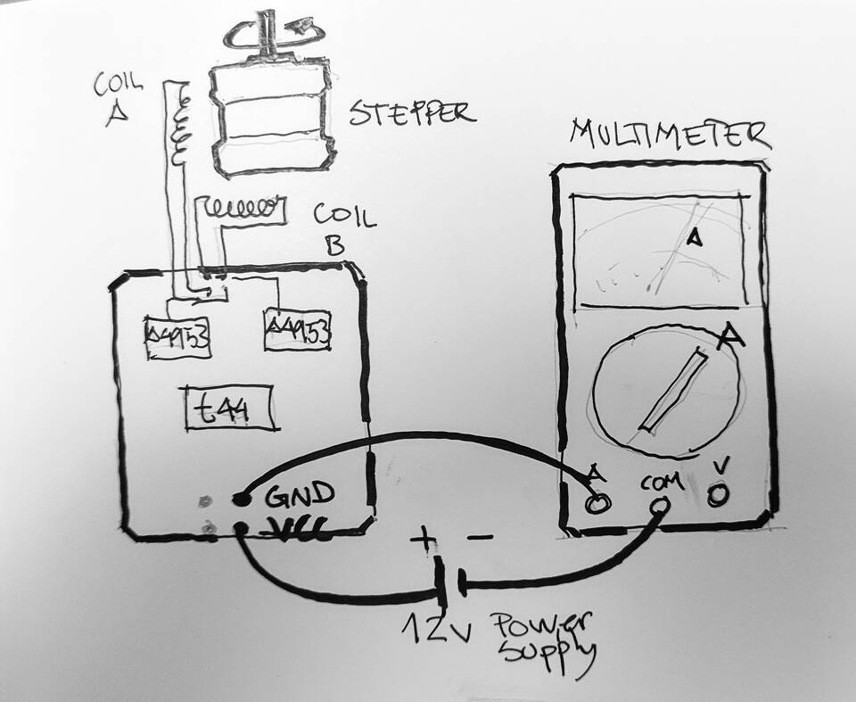
To measure the current drawn from a battery or power supply, we need to connect the amperimeter (or multimeter) in series with it.
I used one of the boards I made during week 13, with this arduino code:
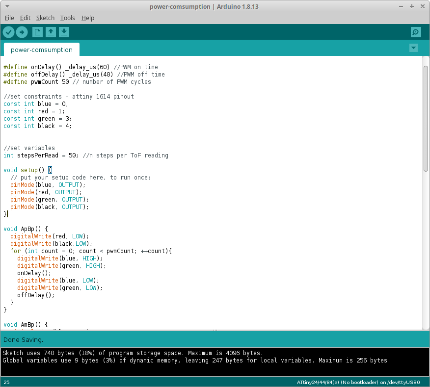
I wrote this piece once I had finished my final project, and reused this board, which I previously thought was dead. It is not, it worked perfectly fine. Than means that many of my problems during this weeks was my lack of knowledge of what was going on, both in the physics of the motor and the code of the microcontroller.
The power consumption while turning at this speed and under this load is, therefore, P = 0.56 * 12 = 6.72W
All assignment files are here: