8. Computer controlled machining: a fun covid week
According to Neil, this is one of the most fun and creative weeks of the cicle. I agree, but I can already see the end of the week, and I fear not getting rid of the designer's block right away... There is so much that I would like to achieve, that I hope I don't end up messing up. Also, my cnc machine is not 100% ready yet. I have tried hard to squeeze all tasks in the previous weeks, but I just missed it by one full day dedicated to fine tuning and finishing the universal vacuum system.
Group assignment: Universal vacuum hold down
In my humble opinion, a universal vacuum hold down for a 4x8 cnc mill is the first add on that should be thought of when installing one of this machines. The main reason is not the increased production rate, due to faster setting up and unloading the of the bed; instead, what I find way more important is that, with such a setup, you possitively know where the bottom of the stock is. And when you are dealing with manufacuring tolerances o about 0.1 mm, that matters a lot: pockets for mortise & tenon like joints need to be that precise, not to mention other processes such as kerfing for bending wood.
Vacuum holding down is kind of magic. When you learn that a reasonably powerful vacuum pump can actually suck through porous material, such as MDF, it really becomes a game changer when it comes to cut large sheet stock. Atmospheric pressure is always there, you like it or not, but since it happens simoultanously in all directions, the weight of the air above our heads gets cancelled out and we do not feel it. But... what if we remove the air below a surface? Then, indeed, all the weight of the column of air above that surface will fall upon it. How much weigh are we talking about? Well, that depends on several factors, such as weather conditions and altitude. Being where I am, near Madrid, at about 650 m above the sea level, that is roughly 0.93 kg / cm2. The thing is, a full 4x8 standard sheet is 244x122=29.768 cm2. So if we could get a theoretical perfect vacuum, the hold down force would be equivalent of having over 27 tons on top of the board. Of course we are not going to get anywhere near that value, and there is no need to it. I hope that I get everything ready as soon as possible so I can show what kind of performance can we expect.

Vacuum hold down is massively used in the woodworking industry. But, most of the time, not universal vacuum. For what I have seen, commercial solutions of universal vacuum consist of a slotted hard and non porous material, such as HPDE or HPL. Usually, there is a perimetral groove, 6 mm wide and 5 mm in depth, in which you place a rubber band to seal the area where you want the vacuum to be applied. In my opinion, the main drawback is that, as you skim off the sacrifical board, it will warp, making it more and more difficult to get the vacumm.
So, in order to avoid this, the best strategie I found is to fabricate our own universal vacuum table. Last time I did it, the chanelled board was directly glued to base board of the machine. It worked great, the problem was that I was forced to destroy it when I had to move the machine. So this time I decided to prepare 36 nuts and bolts, machined in the center of some of the squares, so the whole system can be dissasembled.
Actually it is kind of neat that the machine itself is making some of its own parts. The bottom board of the vacuum table is a MDF board, that had the backside and edges sealed with polyurethane barnish. I used a grid of channels of about 40x40 mm (between axis), and divided the vacuum table into four sections. I noticed two mistakes, one that the spindel was turning at 16k, which added quite a lot of vibrations, the second, that the end mill was way too dull, so the resulting cut was not as good as expected. After the channels are milled, the next step is to seal their bottom and lateral parts. I painted them using leftovers of polyurathane paint, in different shades of gray.

Once it was finished, I skimmed off 0.25 mm from the top. To do so, I used a 30 mm diameter end mill, at 9,000 mm/min @ 18k rpm. While the job was getting done, I realized that steps in the Y direction were visible. Probably it is due to a missalignment of the Z axis. So in the future, I will redefine the skimming strategie, instead of spiraling it will go along the X axis.
Next was time to test the vacuum. With the help of my classmates, I fitted another 19mm MDF board on top of the grid. After carefully fitting it, I turned on the vacuum pump, and laid a piece of scrap wood on top of the board. To everybody's surprise, it got fixed like both parts of wood were magnetic. Next step was, appliying vacuum, skim off 0.25 mm one side of the sacrificial board. MDF is a little bit more compact (less porous) near the surfaces, so this skimming helps with the airflow. Unforntunately, at about half the way, we suffered a power down. I later learned that I need to upgrade the electrical service, for the 4.8 kW of the vacuum pump.
Group assignment: testing cutting strategies
While working at furniture making, one of the first lessons I learned was that parts should come out clean right out of the router. At the time, it took me a while to figure out the right settings to get the job done. The feedrate which drew better results for me was way faster than the suggested from the machine manufacturer. Usually, for large parts cut of birch plywood, I set the feedrate to 9,000 mm/min (354 inch/min) and the spindle at 18.000 rmp. I recently found in the CBA web site a speed and feeds calculator. In it, the suggested settings for OSB and MDF (my guess is that it will be roughly the same for plywood), and outputs a feedrate of about 6,000 mm/min @ 10,000 rpm.

As soon as I get out of the lockdown, I will make test cuts, using 14 mm sided squares, with both those settings, to compare the result.
Since I mostly always rely on vacuum for holddown, I use the onion skin technique to keep vacumm looses at a minimum for the maximum time. Also, a quite useful strategy to achieve a great edge finish has been doing all the cutting in conventional direction, with an allowance offset of 0.25 mm, and then, the last cutting pass in the climb direction, with no allowance offset. Using Vectric software for toolpaths, there is an option to achieve this directly in the profile tool. But I usually program two different toolpaths, one for each direction, so first all the toolpaths that do not get to the bottom are cut, and only at the end, the last mm of material gets cut along the pass that smoothes the edge.

For the test cut, I will cut an 120 mm sided square, with different parameters, to check differences. Due to the machine acceleration, in this cut it will not reach the 9,000 mm feedrate, so I will cut a longer piece to try to identify differences.
| Cutting parameters | x dim | y dim | edge quality |
|---|---|---|---|
| climb-6000-10k | |||
| conventional-6000-10k | |||
| combined-6000-10k | |||
| climb-9000-18k | |||
| conventional-9000-18k | |||
| combined-9000-18k |
What I found out is that the edge quality is still great, @ 6000 mm/min and 10k rpm. And the cutting is much quieter, so I will use this settings for the 6 mm end mill.
The runout is negible for the settings I have been using, considering an acceptable tolerance in something big of 0.1 mm total. Within that margin, most common joints have a tight fit, using birch plywood.
Make something big... and useful
For this week's assignment, I feel the need of building something not only big, but useful. I've been thinking what to make during the last three weeks or so, because I knew this moment would inexorably arrive, but couldn't really find a pain point which I really engaged with. As a backend process in my head, it was the mantra it has to be useful.

Finally, during Neil's Wednesday recitation, I picked up the very important role home labs set ups are playing in these pandemic times. I myself am struggling fitting it in my home, trying to keep it tidy and simple. So maybe, it occured to me that some sort of electronics desk could be something that is worth designing.
Home fab electronics desk - toolchest
When first thinking about this item, my firs thought was who has done what beforehand. Within my references, I found Unto This Last K Desk, that lacks the electronics storage system, and Opendesk Lift Standing Desk. This second one kind of has the space to fit all the storage required
But then I thought that, maybe, a piece of furniture like this, would end up being bulky, and that, in the end, most houses already have desks or tables, although not dedicated to electronics. So, what if, I divide the piece in two: desk + toolchest.

That way, it only gets done whatever is neede in every case. Also, for next spirals of development, it could be used for mobile or shor on space fablabs, to set working stations wherever needed. So next I set the desing goals:
- Specific place for [almost] every item in the home lab
- Fully retractable trays / drawers
- Mostly fabable
- Closed compartiments, for tidiness
- Portable and stacable
After that, I sorted all the stuff in groups. I decided to use an A4 sheet of paper as base guide for the size of the different trays. I ended up grouping everithing in 8 different ones, and I measured the maximun height of every set (all units in mm):
- Testing - 32
- General tools - 18
- Cables - 30
- Cutting - 22
- PCB milling - 30
- Measuring - 14
- Soldering - 52
- Connectors - 15

In addition to that, all of the tiny little electronics inventory, which I hope to fit in additional trays conveniently. But for those, I consider that the form factor is not critical. Next step was to decide the cross sections of the trays. Of course there are many ways to skin a cat, but I decided that for this project I will use birch plywood, and I just love the looks of the stripes in the edges, so I will route out by layers the needed parts to isolate every group of items in every tray. The cross section of the trays are:

I decided then, that the height of the toolchest would be about 300 mm, in which I could stack all the trays needed. My firs thougth was to make a rather big toolchest, with two 300 mm modules in the middle, as shown in the sketch. There would be plenty of room for future addons, such a power supply, but I am thinking that I might do a bit smaller version, at 900 mm width, that still holds all my stuff inside, and is more portable. Or maybe, I just build the large one at 1,200 mm, that stays in the basement, and then another tiny, at 600 mm, that I can easily move around my house as I see fit. I still have a couple of days till I decide. And the nice thing about modularity is that I get to choose different envelope and still the trays are valid.

From here, my usual workflow would consist of sketching by hand all 2d parts, assigning parameters and stablishing geometric relationships. As I mentioned during computer controlled cutting weeek, I find it better to just parametrize and script 2d objects in the bits part, since in the atoms we will be dealing with sheet stock that can be characterized as being 2d. Then, it is very straightforward to assing and map layers in the drawing file to every toolpath required.
But, since the only way I know for now how to do it is using Vectorworks, and it is not a very common software, I will use Freecad for this assignment. The first thing was to set the main parameters. I will be using 12 and 6.5 mm (nominal) birch plywood, the params for those will be tMax and tMin. Then, the different trays height will be calculated based on those (tray15, tray21, tray33, tray 51). Since I started designing from small to large, my main parameters in X and Y will be trayLenght and trayWidht. The total width, height and length of the toolchest will be calculated (tWidth, tLength, tHeight). I will also use an integer to define the number of spans of the toolchest (spans).

First, I started modelling everything in the same FreeCad document, honestly, the way I would do it if using Fusion360. But after about three hours, I had only modelled three parts, side, bottom and back, and was already struggling at keeping the model from breaking. I even had one crash while attempting a fairly basic boolean operation, so I searched for a different approach to the problem. I found this tutorial, by Wayofwood, in which he set up a teacher file with the parameters, then one file for each part, and used the assembly 2 workbench just to visualize the finished box.
This workflow makes more sense to me, since you do not have to deal as much with shape binders or datum planes, which, in my opinion, are a little bit too messy. I ended up looking for antoher tutorial on the A2plus workbench, by Joko Engineering, that gave me a very good insight of how this workbench works. The main problem with it is that, if you change the geometry of a part ins such a way that the faces get renamed, chances are that the assembly will be messed up when you update it. Apparently, the cause is the topological naming problem, as explained by Brodie Fairhall. There is an option under the A2plus preferences that enables the use of experimental topological naming.

After I had assembled all the parts of the frame and one row of trays, I realized that it did not make too much sense repeating this task. I wanted to follow up the workflow, now getting the 2d lines out of the 3d model, to prepare the toolpaths in the CAM software.

When I changed the spans parameters to make an smaller toolchest, the 3d model also broke, in my oppinion due to the same topological name problem. So I will have to rethink my whole approach to 3d modelling in FreeCAD. I do not like neither the fact that A2plus expects one file for each part. It makes it a little complicated to have all under control.
Freecad files
- Parameters file
- 4 span assembly
- Back side
- Top side
- Left side
- Right side
- Divider type 1
- Divider type 2
- Divider type 3
- Tray 51
- Tray 33
- Tray 21
- Tray 15
- Simple tray guide
- Double tray guide
- Bottom side
- Magnet support
My previous workflow
As I stated before, and during conputer controlled cutting week, in my opinion there is no need to 3d model an object that is going to be entirely made out of 2d parts, when all tooling operations can be defined using just flat lines and polylines. Overall, 3d modelling can be really slow, and even though parametric modelling can help, there are just some options that are better achieved using traditional scripting structures, such as loops and conditionals. Just to illustrate it once again, as adviced by local instructors, I will describe here the workflow, using a bedside table that I designed about three years ago.

During one of my trips to London, visiting Olivier Geoffroy's Unto This Last, he was kind enough to show me how they were able to prepare cutting files at a high pace. It turns out that they use an in-house developed software, which directly allows part arrangement and board thickness adjustment.

Really, the fundamental part of this workflow is to determine both the main parameters that will be used and the geometric relations between different elements. The nice part of scripting is that, once you have defined a procedure, you can execute it multiple times just calling it. The only programming I know is VectorScript. Learning it for my needs was quite easy; what was more difficult was, at the beginning, to find good resources and examples. The best I found is dated in 1999, still in Nemetschek's server, called Custom Solutions.
One of the key benefits of this workflow is that you can sort every element in a different layer, so it will make the CAM procces quite efficient and somehow foolproof. In this case, I added parameters for the lenght, depth and height of the bedside table, widht of the frames and height of the drawer, board thickness and tool diameter. What I could not achieve was to be able to move the subcomponents around whithout loosing the parametrization, which would be great for arranging before knowing the exact thickness of the material.
The following Vectorscript files are just text files. Of course to properly run them, you need to do it inside the Vectorworks enviroment. But it is possible to see the logic of it, as Vectorscript is just a subset of Pascal, and is quite easy to follow.
Dog Bone include file
Bedside table Vectorscript

It would be great to have a similar tool available in an open source program, such as Inkscape, but for now, I have not found the way to get it. Searching for alternatives, I got to Parametric SVG, by Tomek Wiszniewski, and parmetric SVG editor, by Harmen G. Zijp. Both are somehow linked to Fab Labs, the first in Valldaura, in Catalonia, and the second FabLab Amersfoort in Utrecht. I do not know if they are deprecated, or if it would be possible to make use of them as a tool to define parts.
I later found out that Leo McElroy is developing Gram, and I am quite exited about it. As soon as I possibly can, I will get my hands on it,since it seems it is going to be a great tool for 2D parametric design.
Final project test bench
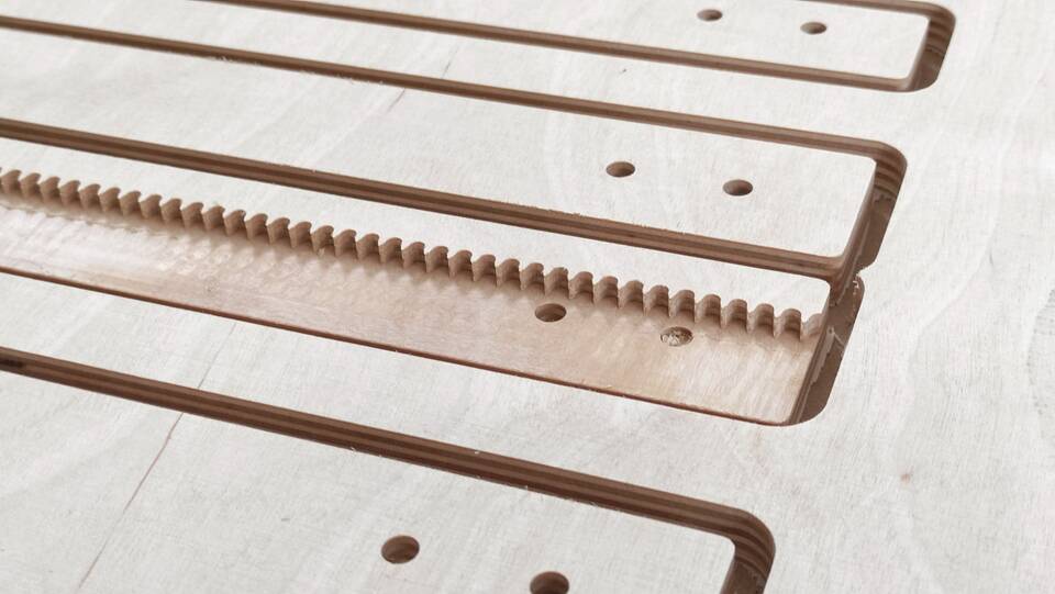
In order to test the fab-o-meterWINK, I made a test bench. It is 1,000 mm long and 500 mm wide. It is prepared so both a rail and and "irregular wall" can be fitted along the long sides. The first rail milled is a rack, following Fellesverkstedet fabricatable machines modules.
First thing before machining anything is to check the material thickness. I am using nominal 12mm birch plywood, and, as can be seen in this table from Wisa, according to EN 315 - Plywood tolerances for dimensions, actual thickness can vary quite a lot:

And indeed the actual thickness is different from the nominal:

Next, I used a feeds and speeds calculator, found in the public pages of CBA at MIT:


The CAM software used is Vectric Cut2D. The process generating the toolpaths is quite simple. In this case, I set an 0.2 mm allowance for the first cuts, up to a depth of 10.5 mm, in the climb direction. Then, for the final pass, the allowance is set to 0, the depth of cut to 11.7 mm and the direction conventional. With those settings, you get a finishing that needs almost no sanding. The spindle speed was set to 10.5k rpm in the first cut, and slightly higher in the final, at 12k rpm.

Also notice that the maximum depth of cut for the tool used in the final cut is set to 20mm, so it cuts the profiles in just one go. In this toolpath is where you should add holding tabs if needed. In this case, I addded them becausesome parts are quite narrow, and vacuum holdown could fail there.

I also set another two toolpaths, one for drilling the positioning dowels, and the other with a smaller endmill (1/8" diameter). For the drilling, I set the rpm to the minimum my spindle allows, which is 6k rmp. On the other hand, for the 1/8" mm bit I used the maximum, at 18k rpm. I then saved all the toolpaths to the same file: every time there is a toolchange in the g-code (T1..T3.), the machinign will stop.

And this is the machine refining the rack, with the 1/8" end mill:
This video shows a smooth cut, running at 7000 mm/min. Note that the video is not accelerated:
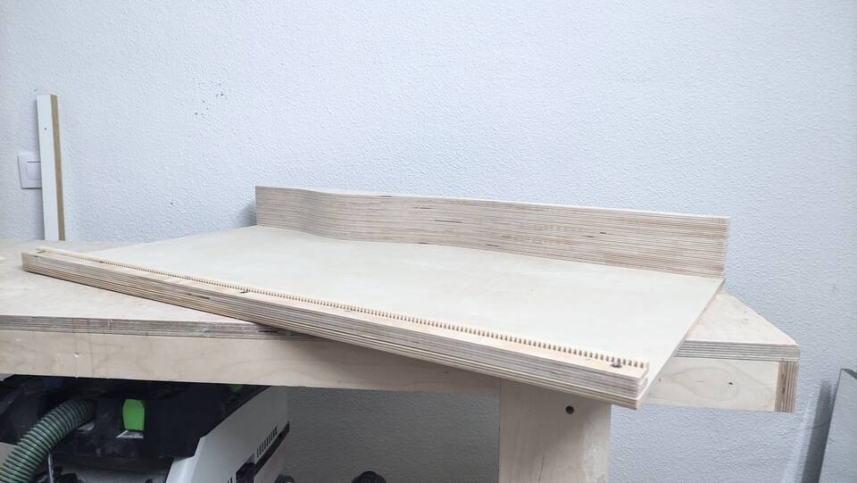
After just a few minutes, the job was finished: no parts moved, eve there was just a 7 mm minimum clearance between parts.

And this is the cut quality, with no signs of tear out. I used for all cuts a two flute straigh end mill. For all the testing I have done, I find that the humble straigh end mill does a better job than the spiral ones when it comes to machine wood.
Once the parts are stacked, just light sanding will be needeed to remove tabs.

I also used insert nuts, so both the rack and the wall can be replaced for different versions if needed:

The finished test bench, after glueing the wall and rack, and sanding tabs and glue spill-outs:
Test bench FreeCad file
Test bench Rhino & Vectric files
Machining the trays
During wildcard week, I had the chance to finish the trays, and use them for that week's assignment.
The trays / drawers were designed in Rhinoceros, since they all have different geometries, and I did no see the point in parametrizing them. They are made of several layers of plywood: the firs one is always machined an pocketed 6.5 mm thick, the second outlines all the compartiments in a 12 mm layer; from there on, it is only the outer perimeter that gets machined.
It took the machine over half an hour to get the job done:

I used the same cutting strategy as usual, climb milling, leaving a 0.2 mm clearance on all passes up to a depth of the total minus 1.5 mm, then a single final pass to the total depth in the conventional direction and with no clearance. The edge quality was nice:

This time, I had really narrow parts, of just 12 mm. I was a bit concerned about parts moving during the final cut, so I did not cut all the way through the stock, leaving a very thin skin that I later removed with a cutter:
Next, I assembled them, using PVA glue and dowels for positioning:

The outer part is made of bent lamination, using oak veneer as finishing surface. Top and bottom parts were first veneered with 0.6 mm oak and then machined. The oak is finished with Osmo Polyx hard wax.
Dog bones
Whenever I am designing a piece of furniture that is going to be made more than once, as I stated before, I parametrize it using Vectroscript inside Vectorworks. I have written there several functions that are called within the polyline drawings, and take care of the dogbones. It is possible to pass the tool diameter as parameter, so once drawn, it is easy to change.
Some other times, if I am just testing out something using Rhinoceros and Grasshopper, I use definitions such as dog treat, by Darcy Zeleko, that eases the task.
If there are just a handful to be made, such as the case in this object, where I just had some of them in both top and bottom parts, I use Vectric's dogbone creation tool. It just changes the way the clicked corner on a polyline gets drawn: it can either be a normal fillet or some of the dog-bone like fillets that allow parts to fit into each other.

I usually set the dogbone to have the end mill diameter, adding about 0.25 extra to assure pieces fit correctly.
What worked, what did not
First thing that did not yet work was the vacuum hold down. Not for the setup itself, that looks great, but just because I need to upgrade the electrical service, which was not enough for the 4.8kW vacuum pump. The set up holds parts, even with all the sections of the bed open.
Modeling in FreeCAD only partially worked for now. Even though I have individual parts, the number of spans that the toolchest will have will not be parameterizable. Other than that, it is usable. On the other hand, it was nice to revisit how I used to prepare cutting files with Vectorscript.
Lockdown. I started feeling bad on Monday, and decided to stay at home. Tuesday I tested positive for Covid-19. For now, just with fever, overall soreness and loss of taste... so yes, all the cutting will have to be postponed... just one of the perks of the Fab Academy in a global pandemic.