3. Computer aided design
The goal for this week is to try several CAD tools. Due to my background, I have worked with quite a few CAD tools, such as AutoCAD, Sketchup, Arris, Microstation, Rhinoceros,Vectorworks... I have also some experience using both Fusion360 and FreeCAD. I would like to use the week to study a bit more about surface modelling, more specifically dive into the topic of curve continuity and class-A surfacing. I would also like to to try 2D raster & vector apps which I had heard of but never installed, such as inkscape, GIMP, ffmpeg and Image Magick. I will also install some of the recommended apps, such as My Paint and geeqi.
My Paint
The first app that I would like to test is [My Paint](http://mypaint.org). I will use it along a small wacom tablet, and since I have a second display for my laptop, the first thing is to map the tablet just to one screen in Xubuntu. I followed [this article](https://github.com/linuxwacom/xf86-input-wacom/wiki/Dual-and-Multi-Monitor-Set-Up) from [The Linux Wacom Project](https://linuxwacom.github.io/).
- First run
$ xsetwacom --listto find the name of the Wacom device to map, in my case, "Wacom Intuos BT S Pen stylus" - Run
xrandrto find out monitor name, in my case "HDMI-1" - Run the command
xsetwacom set "Wacom Intuos BT S Pen stylus" MapToOutput HDMI-1
To install, I downloaded this AppImage, made it executable with sudo chmod +x filename.
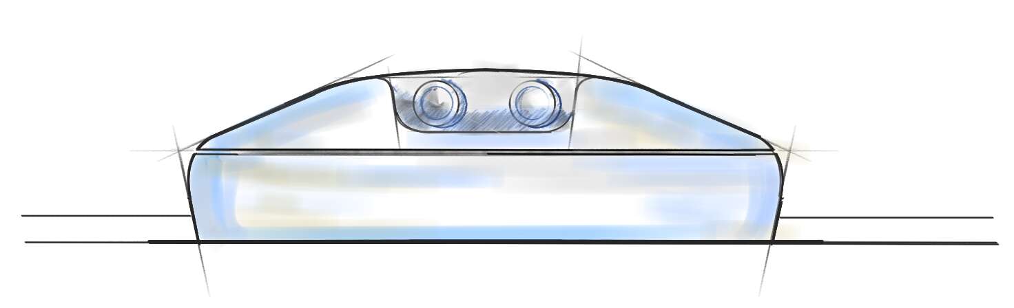
I tested it for about one hour, and drew this possible front view of the Fab-o-Meter. It took me a while to get use to draw using the tablet, since I had never used before for this purpose, I had only used it for on-line reviewing my students' work. Overall, My Paint worked nicely, once got used to keyboard shorcuts it was fast and powerful. The tools I liked most where the straight line / arc tool and the symmetry option. I missed in that one that the axis location could not be saved, for later use.
Inkscape
Instaling from terminal sudo apt install inkscape. Just to give it a quick run, and see how good it can be at vectorizing vectors. I donn't know if anyone in previous editions of the Fab Academy noticed, but three events are aligning: CAD Week, Computer Controlled Cutting Week and Carnival!!! In my opinion is the perfect chance to:
- Get a picture of Neil
- Vectorize it
- Combine a drawing and a cutout in the vinyl cutter
- Poke two holes in the ears and add a rubber band
- Now we can all be Neil in Carnival!!!!
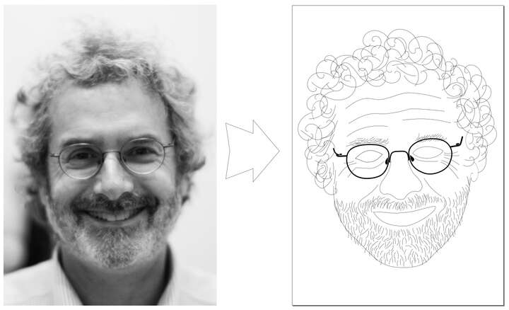
Ok, I did not ask my local instructors if this kind of behaviour is allowed in the Fab Academy... I will ask tomorrow, and if it is not possible to make this carnival masks, we could also try with Adrian's face!!!
Geeqie
Installed from terminal $ sudo apt install geeqie. It is very fast loading images, and I really liked that it shows the histogram. But the truth is that I am usig much more gThumb for light image correction and supervision. Most of the pictures making for the Fab Academy, gets done in my phone, strored in an album per week and then resized and compressed using ImageMagick
ImageMagick
This is one of those tools I want to learn about this week. I downloaded de AppImage file, run chmod +x magick and placed it under my $PATH.
To test it, I modified the drawing I had just finished with My Paint, resizing it to 960 px wide and 60% compression: $ magick my-paint.png -resize 960 -quality 60 my-paint.jpg. And just like that, it went from 200 kb to 28 kb. Really a very helpfull comand line tool to quickly use appropiate file format, size and compression of images. I am pretty sure that I will use it a lot along the semester.
I did have the impression that the -resize 960 modifier did not work, so I will have to double check it. I also found this commands very useful, from stack overflow:
resize image to width 25, keeping aspect ratio

        convert -geometry 25x src/image1.png out/image1.png
resize image to height 25, keeping aspect ratio
convert -geometry x25 src/image1.png out/image1.pngconcatenate images horizontally
convert +append src/image1.png src/image2.png out/image12horiz.pngconcatenate images vertically
convert -append src/image1.png src/image2.png out/image12vert.png
FreeCAD
I have used FreeCAD a little bit in the past, mostly just the sketcher to draw 2D parts, which I like a lot. I have almost no experience with the Part Design and Assembly workbenches. So I am planning to spend some time using this tools. I would also like to load something into the FEM module and check out the results. I'm thinking about a geodesic dome, smaller, but similar tu Buckminster Fuller's.
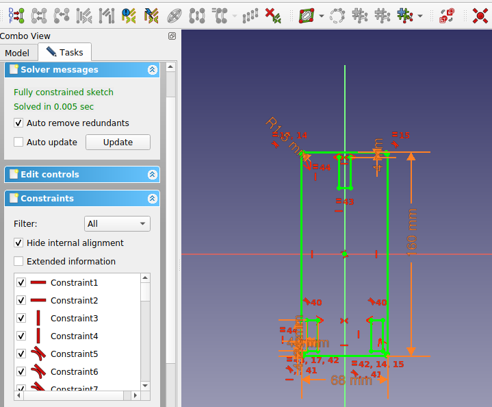
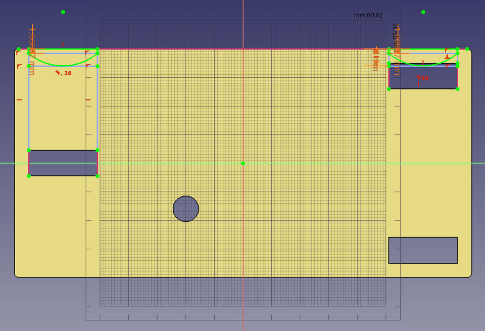
In a second thougth, I am going to model first a possible moving cart for my final project, importing parts (such as bearings) from [McMaster]() website, and going parametric. Definign parameters using the embedded spreadheets in FreeCad is quite straightforward, and very versatile. After about 20, I was able to have the first fully constrained sketch, of the base platform, centered and with gaps for the bearings locked into position.
Modeling the first of the bearing supports was quite easy. I watched Kris' class, and it was very helpful to have the shape binder explained. Also, thanks to to this class, I started using more keybord shortcuts, to cycle between polyline modes m, add vertical v and horizontal h constraints, and dimensions shift+v or shift+h. Also, now there is a field in the spreadsheet to add the ailias to the parameters much faster than accesing through the contextual menu.
When I had to replicate all the bearing shaft supports, it got a little trickier. I stayed in the Part Design workbench, and tried not to draw another sketch. Finally, I could not figure out how to completely do it this way, so I ended up drawing a second sketch. I found out that you can not use a linear pattern feature as the starting feature for another linear pattern feature. Overall, compared to what I am used to in Fusion 360, it is not as flexible. (Or I couldn't find my way to an efficient workflow).
The next feature to be added were the guiding pads. This time, to make it faster, in the sketch I defined two of them, and then applied a mirror to that feature.
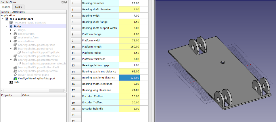
Then the last step for now for this body was to add pads to screw in the electronic board. I added some more parameters, to define the gap between board and platform, electronics board dimensions, and pad and screw diameters.
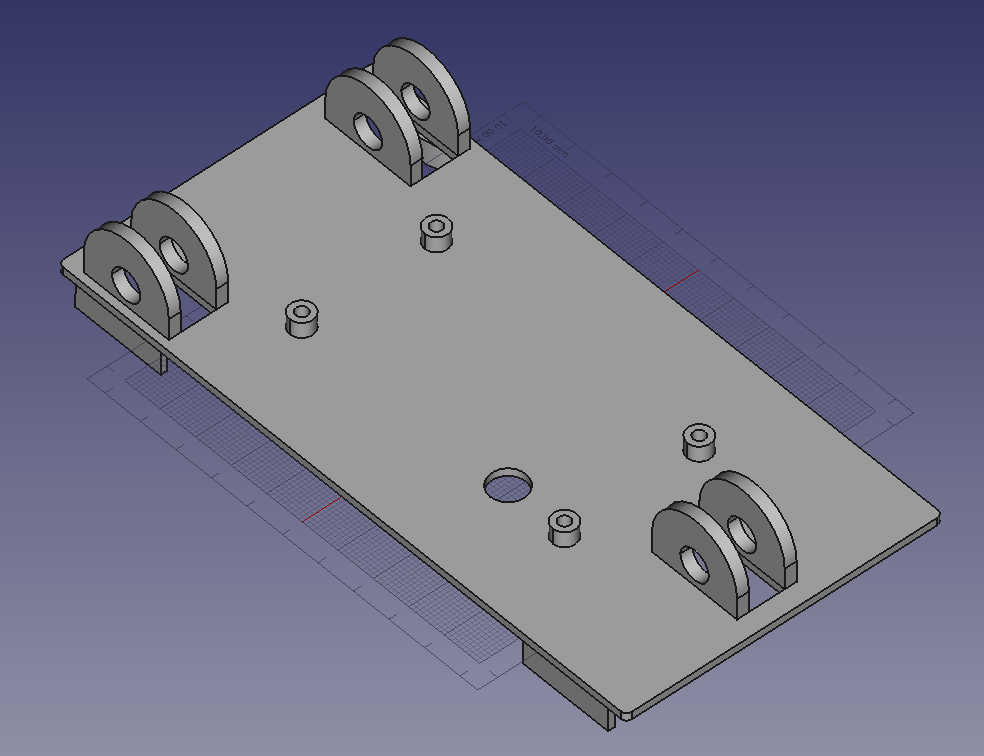
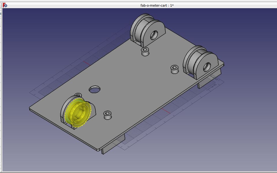
The bearings were download from McMaster-Carr in IGES format. They are 608-2Z, 22 mm in diameter with a 8 mm shaft. I placed the firs of them in the origin, (center of the platform), rotated and moved using the Placement panel. All of the values inserted are parametric, so the bearings will move into the right position if the platform changes dimensions.
 Download FreeCad File
Rhinoceros
I use Rhino quite a lot. I find the curves and surfaces tools quite impressive. Panneling toolsis a really an amazing and easy to use packege for complex geometry modelling. I always recomend to my students the courses offered by the developer of the tool, Rajaa Isaa, which are very concise and clear.
Since one of my goals this week is to dig deeper into surface continuity, I will go through this series of video tutorials, by Schuyler Greenawalt, and try to apply it to modeling an enclousere for my final project. To be honest, I have searched quite a few times for propper ways of modeling surfaces, and I have not found reliable sources of information as complexity increases.
Single span curves and surfaces, have n+1 control points, being n the degree of the curve. One of the reason behind why using single span curves and surfaces is to perfectly match adjacent surfaces along their edges, and get, as a result, a watertight model. Another quality of single span surfaces is that when divided, generates two single span surfaces.
I found very useful the way to define single span curves, starting with just an straight line (degree 1 curve), from start to end of the desired single span segment, and then changing the degree to fit. That way, you can be sure that your guide curves will be single spans.
Sculpt and match - a workflow in which you sculpt the surfaces you are working with, and then match them to the surfaces that surrounds it. Try to keep surfaces with only with one isocurve in either direction. Overdefinition of surfaces is one of the first problem when trying to model complex geometries. The more overdefined it is, the more difficult it will be to modify or adapt the model later. It is important to define every surface according to the matching requirements that it will have with adjacent surfaces. If only tangency is needed (G1) first row of control points should be alingned, wheras if curvature continuity is needed (G2), 1st and 2nd rows of control points or each surface should be aligned.
There is also the convinience of having all surfaces have four sides. The tutorial describes a technique that he uses everytime there is a 3 sided surface. It basically consists in creating a sphere in the adjacetn 4 sided patch, to extract and extra edge and turn the 3 sided patch into a 4 sided one.
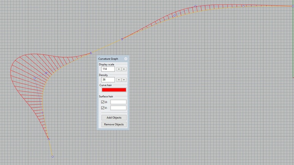
There is a set of rules froma Autodesk Alias whick makes a good read before drawing the guide curves of a model. It is important to notice how curvature should accelerate. Any straight part of the model should be defined by an straight line, degree 1 curve. The workflow for drawing the curves consist of first drawing a line that goes from start to end point of the section, and then use the command ChangeDegree, that it will add a control point. That way, we ensure that we end up having a single span curve once we have addapted it to the desired shape. We need to aim for smooth curvature graphs.
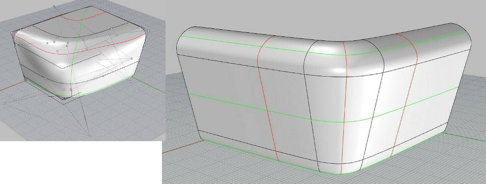
I tried all the abovementioned techniques, and you do get more control over the surfaces that you are creating. I see two main drawbacks, one is that it is (at least for now), a rather a slow workflow, so it is not worth using it during early stages. The second one is that it inherently creates polysurfaces, so you in practice, you have to say goodbye to panelling tools.
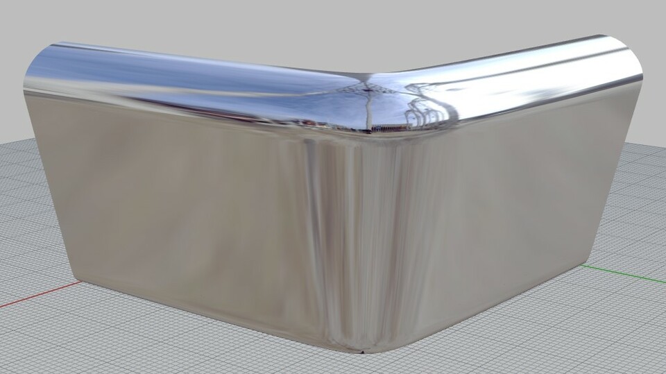
I finally managed to get the corner with G2 continuity, but it took a lot of effort to achieve, and I did not finish the upper part of the box. Still, it was a great experience, and I did learn quite a lot.
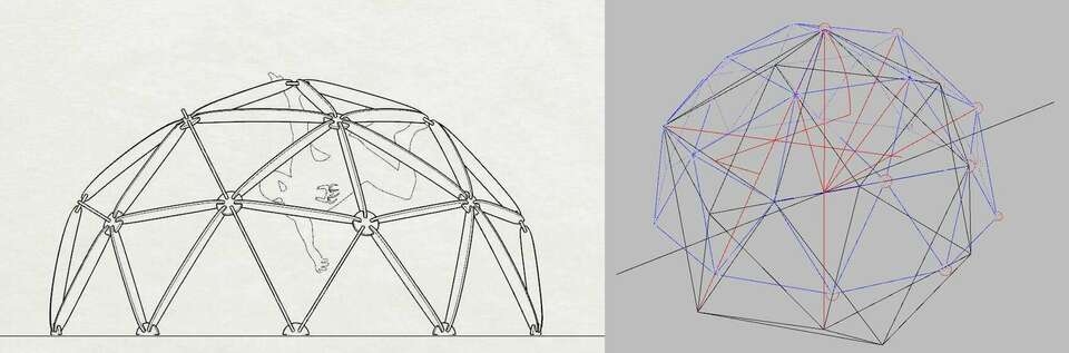
I would also try to use the FEM module in FreeCad, so I am drawing from scratch a 2v geodesic dome. I know there are several methods, I started with a penthagon and five triangles. It was fun remembering platonic solids geometry, last time I had to draw something similar I was still using rulers, T-bar and compass, so it was really nice to use all of Rhino C-Plane possibilites.
FEM Analysis
After the geodesic dome was finished, I exported as IGES, using Solid Works solids default settings, and imported in FreeCad. I had never run such simmulation, so I watched a tutorial from "https://www.youtube.com/watch?v=dhrynRdBOIg&t=637s"Joko Engineering. It opened smoothly in FreeCAD.
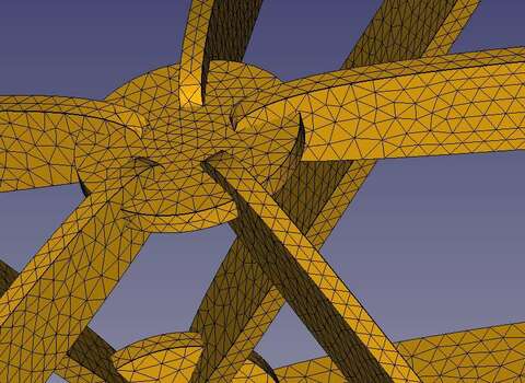
I applied support constraints in the base, a 60 N downwards force in each node, and edited the material parameters for a OSB board. There I found the first problem, since I did not figure out how to add anisotropic properties to this material. The real problem came a bit later, since the program needs to, first caculate a mesh, and then run the analysis. I could not get a valid mesh out of the geometry, so I checked the original geometry and found some non-manifold edges. So I will hav to remodel it, probably simplifiying it and paying attention so the final object is manifold.
Antimony
After the class I felt a little curious about Antimony, and what F-Rep implies. After having watched Kris' class on FreeCad, I searched on his Fab Academy Site, and saw that he experimented a bit with Antimony, so I decided to give it at least a couple of hours. Given that what I am triying to achieve in surface modeling is, in the end, a blend of several bodies, I wonder if similar results can be acomplished using this workflow.
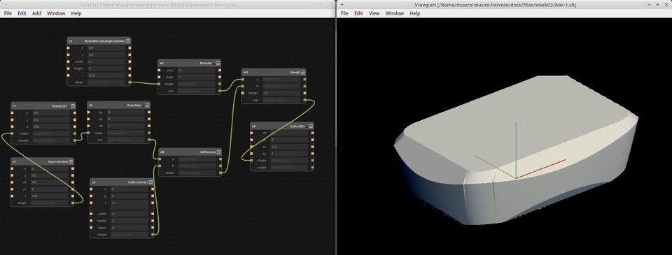
It was fun to play arround with it, trying to achieve an interesting shape for a box, using morphing and several more elementes. I used in the first example just the morph command, with a truncated cone and box.
 Download antimony file
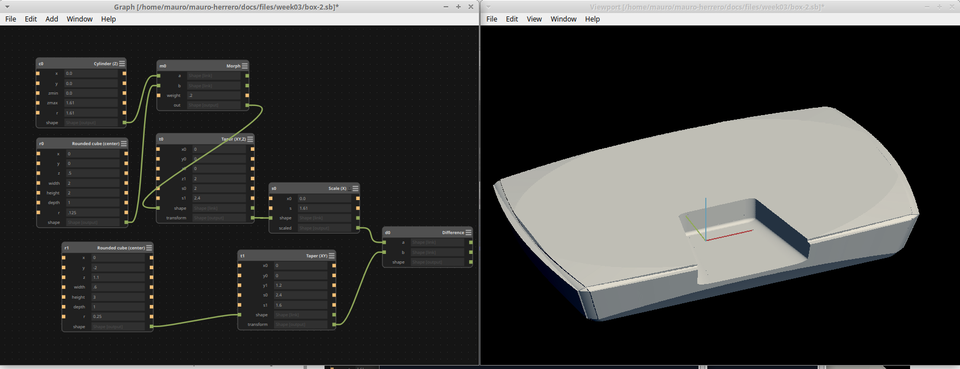
The second time I tried, I started out with a cilinder and a rounded rectangle, and after morphing, applied taper to get tilted sides, and finished by removing a piece for the distance sensor.
 Download antimony file
It was fun and definitly worth it experimenting for a bit with this program. I will look for more examples in the future, to make more shape blending. I do not know how difficult it would be to start with custom curves.
Fusion 360
Once modeled in Rhino, I will explore the options in Fusion 360. I would like to watch this video on the same topic, but approached with different software. If not, I will explore the shape using the form tool, following this tutorial.
Blender
Believe it or not, Blender is one of those software packages that I have installed several times, but never had the time (or will) to use it past over the first tutorial. So I have to manage to spare at least a couple of hours to test it.
Tuesday night. Yes, I have to admit that tasks management has been rather poor, and that is entirely on me. But still, let's see if I am able, in just under two hours, to make the fab-o-meter move along the rail.
Blender was part of my Xubuntu installation, so nothing to install this time. Since I have never used it before, I am going directly to start watching the Blender Fundamentals series.
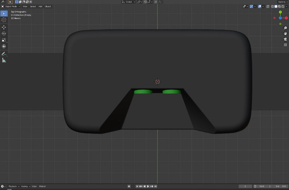
I exported the model as `*.obj`, and worked nicely. The mesh fitted the geometry seamlessly, as this picture shows:
After watching the first four chapters, I swiched to another tutorial, by Grant Abbit, which is more specific on animation*. I will not dive into modelling in Blender for now. I starts by animating a simple cube, inside the Animation workspace, first thing is place the cube in the starting point, an inserting in the time line a location, by pressing i once the cube is in position. Then, dragging the timeline to the desired frame, insert another key. It is important to remember that everytime you capture a position of an object with a key, the object will return to the position it had when first captured.
For the material of the box, I wanted something that did not look too gloosy, and I found this micro roughness material that looked just about how I wanted it. There are literally a zillion tweeks that you can apply to get the material needed, and the nodes workflow works really well. I found it to be a great breakthrough compared with what I was used to many years ago. To bring assets, such as materials from other file in Blender, you can use two methods, append actually copies the asset to the working file, whereas link just adds a reference. I did not spend a lot of time tinkering with lights and materials.
At the end, just for fun, I added a little bump in the animation,just before the box stops. For the output, I used ffmpeg, mp4 format with h.264 codec. I just added the motion blur, to prevent the movement looking jerky.
link to blender fileGIMP
I have been using it during the week, and I would like to do some work with it in some self-pictures that I took during the previous week.