6. 3D scanning and printing
During this week I will test some non standard filaments, such as Timberfill, Ceramic looking, and even cooper, from Virtual Foundry. There are quite a few pieces to print this week, so I will try to have the printer going for as long as possible. It is really great to have it in my home lab, so I can use night time.
3D printing involves generating first the geometry to be printed. I would like to try programming at least one part to print. I wish I was skilled enough to write code that outputs directly STL, but I am afraid that for now that is way beyond my abilites. I will try, at least, to write something for OpenJSCAD, that seems more accesible to me. I will also print some part that will be useful in my final project development, probably the case, so I can test looks and ergonomics. And since I am trying nice looking materials, I will quickly design something simple, (maybe a vase or pencil holder), giving it a twist with Grasshopper.
In the 3d scanning department I am a complete noob, so I will just try to get started with something simple.
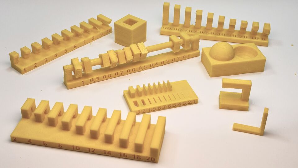
Group assignment: Test prints - desing rules
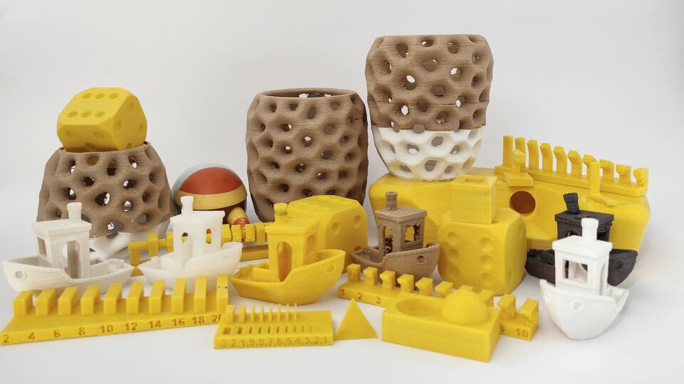
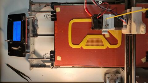
In my home lab, I have set up an old and much cheaper Prusa Clone. I bought it second hand in 2017, but I started using it just earlier this year. For this week, the first batch will be the test figures that Neil prepared. I used standard PLA settings, with 0.2 mm layer height, 10% infill and 3 layer outer shell. I prepared two print files, one unsupported and the second supported, and left it printing overnight.
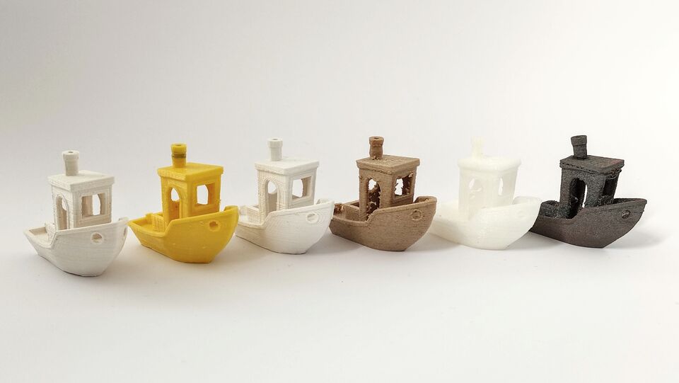
I also planned to print another figure with every filament I found at the Lab, and after showing several to my kids, they decided the best candidate was 3D Benchy. I agreed with them and printed the first one in yellow PLA.
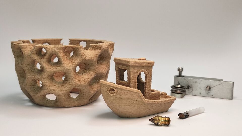
The next material I tested was Timberfill. The slicer used was Cura. I know there are now available more options, such as Slic3r, ideaMaker, Skeingforge, ReplicatorG... so if I have extra time on Tuesday i will try at least one more. Ti is advised to use a 0.5mm nozzle, but I did not have one that day, so I went on with the 4 mm one. The print came out quite nice, just with a little strinning between sides of the doors, but this material is very soft and easy to remove once finished. It has that MDF - wood warmness, and retains the plastic elasticity. Settings were: 0.2 mm layer height, 10% infill, 2 layers outer shell, 50 mm/s and 175 C. When I tried to print the other part, the nozzle got stuk, so I decided to wait for a larger diameter.
The following in the list was a modified PLA, by Smartfill, that claims a matte ceramic look, Ivory White color. The material seems a little more fragile and thick than standard PLA. 3DBenchy resulted in a strinningless print, but the lines of every layer seem more noticeable than with vanilla PLA. Settings for this material were: 0.2 mm layer height, 10% infill, 2 layers outer shell, 60 mm/sec and 205C.
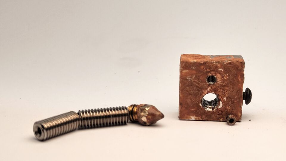
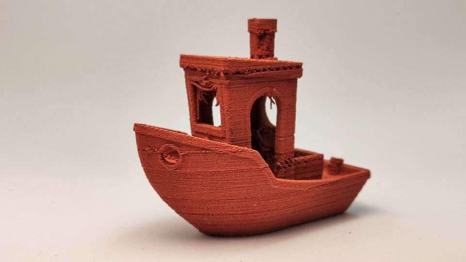
On saturday arrived the extra nozzles I ordered, stainless steel ranging from 0.2 to 1.0 mm, so I finally could move on to test a metallic filament, by Virtual Foundry. The one I used contains over 90% of cooper, beeing PLA the rest. It prints normally, just with a slower feedrate and a slightly higher temperature. The filament feels very brittle, due that it is actually a kind of metal powder with just enough polymer to hold it in shape until transformed with the FFF printer. Afterwards, a sintering process is needed in order to remove the plastic and give the part the material characteristics. 3D Benchy came out rougher than its polymer cousisns, and the chimmeney was accidentaly chopped off its top when removing from the printing bed.
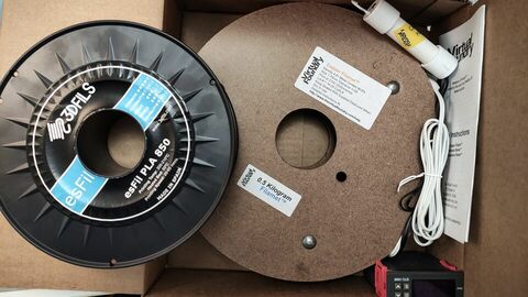
The diameter of the filament roll is way larger than a standard one, so I had to improvise a place to hang it. It is also advised to preheat the filament before it goes into the extruder, but I did not use it and did not have any issue. On tuesday I will go to the URJC Lab to finish the sintering process.
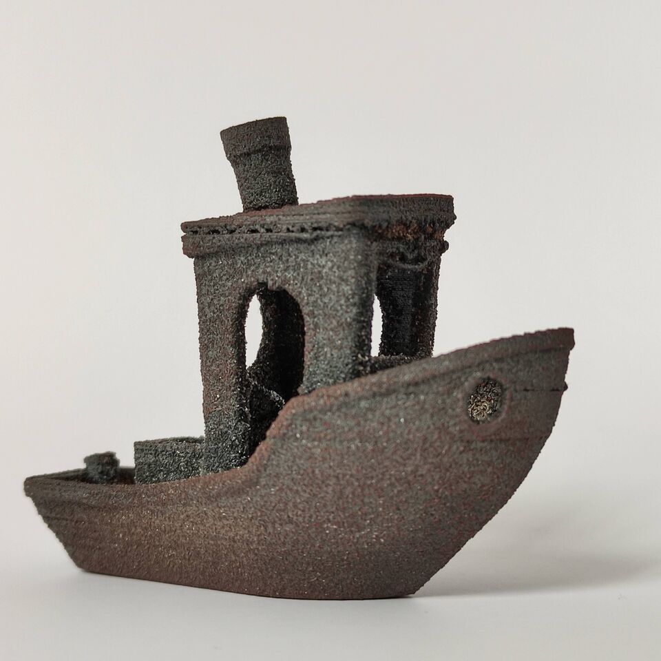
Sintering takes very long. We set up the kiln to ramp up the temperature from romm to 1000ºC during 8 and a half hours, as stated by the filament manufacturer. Then 1025ºC for 1 hour and finally 1050ºC for another 3 hours. Cooling down took also quite a lot.
There is quite a lot to learn about this procedure. First, I layed the piece over one side, and that side came out fine, but the opposite was warped. My guess is that there was not enough support material, and at some point it became a bit fluid. I also do not know why the color is so gray It is because, as explained below, I did not use carbon to absorb the oxigen inside the crucible. I will go on and read something about this, because for now, I know next to nothing. It was curious that it is non conductive, but another small part that I put into the fireplace in my house, is perfectly conductive and really has the look that one would expect from a Cu part.
After a second look at the results in the kiln, I learned that I completely missed a really important point: due to the high temperatures and the fact that the metal is, at first in powder, there is a huge amount of surface of the material exposed to the atmosphere, which contains O2, so the 3D Benchy is totally oxidized. To avoid this, using an open atmosphere kiln like the one available, I should have used active carbon in the outermost layer of the setup, that would absorb the oxigen before it reached the part. The little part that I threw into my fireplace ended up not oxidized probably because of the presence of carbon itself from the logs being burned.
As a conclusion, printing metal parts using FFF is both very time cosuming and expensive. So, definetly, I will only use it if there is absolutely no other way to fabricate the part. And I think that using molding and casting, a great deal of shapes can be achieved
Next material test was Nylon. I used the vendor recommended settings. The filament feels way more flexible, and indeed looks like a quite thick nylon fishing line. A quick search in Google revealed what came to my mind right away: yes, it is possible to use a nylon fishing line. So if for whatever reason I need this material in the future, I will undoubtly test the fishing line, since it is something like 8 fold cheaper. During print, soft little bursts were audible (moisture?), and the look was like it was a thick sticky ice.
| Material | Layer height | Nozzle | Speed (mm/s) | Wall lines | Infill | Print Temp | Bed Temp |
|---|---|---|---|---|---|---|---|
| PLA | 0.2 | 0.4 | 60 | 3 | 20% | 190 | 60 |
| Timberfill | 0.2 | 0.5 | 50 | 2 | 10% | 175 | 50 |
| PLA-Ivory white | 0.2 | 0.4 | 60 | 2 | 10% | 175 | 50 |
| Cooper (VF) | 0.2 | 0.6 | 30 | 2 | 20% | 215 | 50 |
| ABS | 0.2 | 0.4 | 60 | 2 | 10% | 230 | 90 |
| Nylon | 0.2 | 0.4 | 42 | 2 | 10% | 230 | 45 |
Voronoi vase
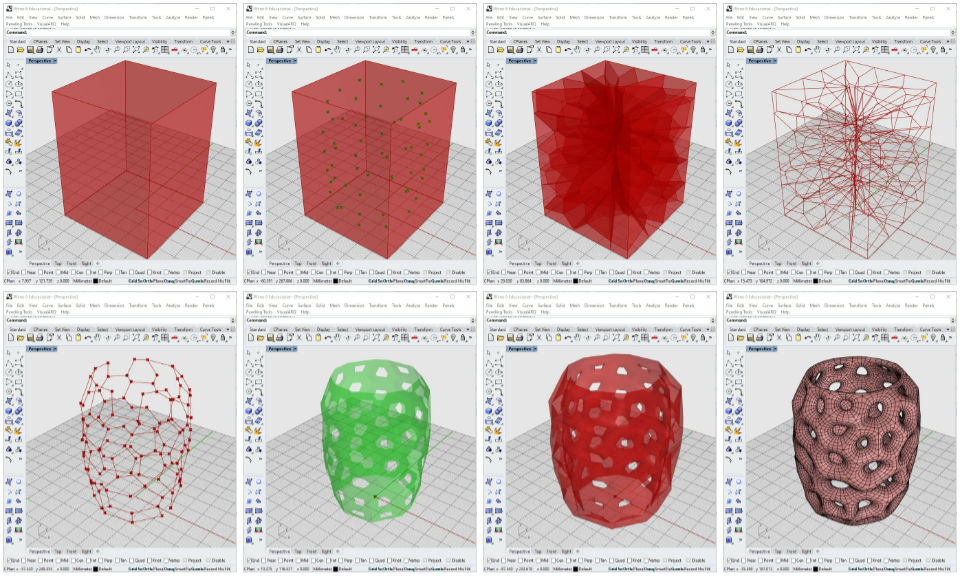
To fulfill the part of the assignment of designing and 3d printing a part that could not be fabricated with substructive methods, I designed a small vase for pens in Grasshopper. I decided to go fully parametric, controling the curves that define the shape and size of the vase with sliders. The Voronoi tesselation includes the creation of a 3d Voronoi pattern, that is concentrically proyected onto the vase original surface. Afterwards, this tesselation is thickened and subdivided using several meshing tools. To achieve this, I followed several tutorials, from both Om. egvo and Parametric House. This is the sequence that goes from the proyected 3d Voronoi wireframe to the final solid.
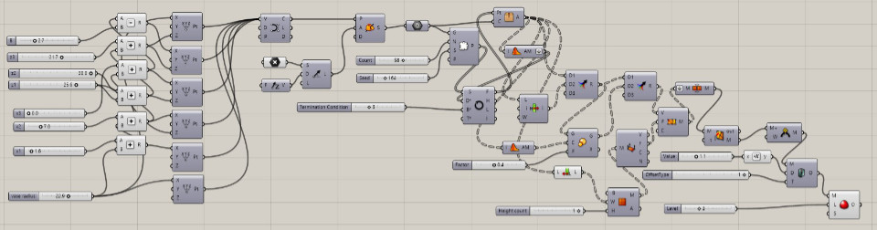 Grasshopper definition for voronoi vases
Rhino 4 file of one of the printed vases
STL file of one of the printed vases
Grasshopper definition for voronoi vases
Rhino 4 file of one of the printed vases
STL file of one of the printed vases
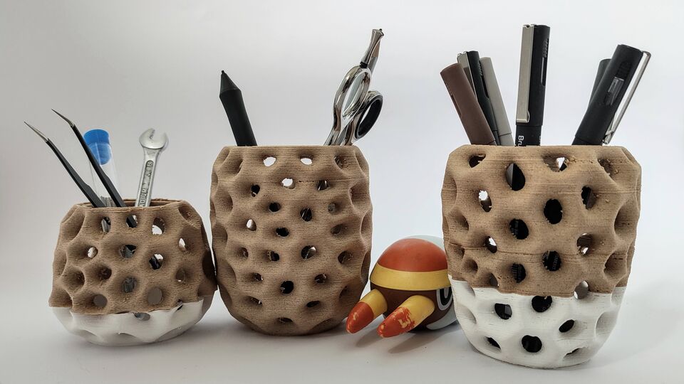
I combined the failed prints, and I think the result of mixing Ivory White with Timberfill, looks nice, so I tried one more print combining these two materials.
I was going to edit the G-code by hand, introducing a line with M140 S50.0 M104 S175.0 (loads of info here, but I found out there is an extension called ChangeAtZ in Cura, so I tested it at height 36 mm. The material change went perfectly fine, just had to briefly pause the printing, change roll, and watch the printer adjust to the new settings. About an hour later, probably somebody in my house messed the settings, and set the speed to 10%. There is a line that is visible, about 10 mm over the change of material. Thankfully, I switched it back to normal and the print finished in time.
Printing a circuit
Definetly, 3D printing is not the smartest way to get a working circuit, but, since I have succesfuly printed a cooper 3D-Benchy, the next spiral for me would be to 3D print a Fab USB Tiny. First, I need to vectorize the traces, then add depth to them, and finally slice and print. Right out of the 3D printer, the cooper is not conductive, due to the 10% of PLA in the material. I am planning to sinterize it in a ceramic oven afterwards
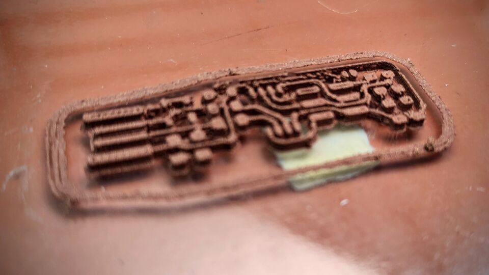
It was not a good idea. Even with the standard 0.4mm noozle instead of the 0.6mm recommended one, traces are just to thin and very close one to the next. Besides that, removing it from my glass print bed was nearly impossible. I also tried printing on tape, but the filament did not stick to it. Maybe it could be printed on top of a piece of glass, or pour some very fluid ceramic that would cure during the sintering procces. There is room for improvement and doing something different here...
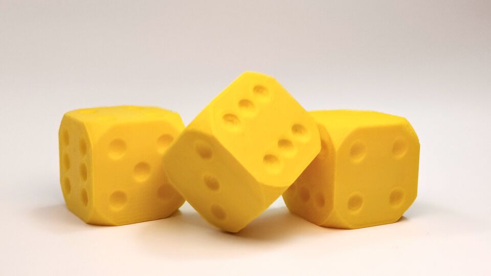
Cheat dice
One of the obvious benefits of 3d printing is that you have access to the interior of any part. Very much like bony structures, that have the denser and stronger osteoblasts were most needed. So, what if I could design a piece with that feature... Since I have already spent a good deal of the week, and no part with such demanding structural requirements come to my mind, it occured to me that I could print 2 dice, one with a standard weight distribution (I know it is not going to be perfect), and another, in which I can mess arround the internal composition of a few laywers near one side. I will do it the rough way: I will get two sets of g-code, one with 100% infill, and the other with a rather low (say 20%). I will use Vim to generate a Frankenstein g-code, that will use the first for the first mm of the piece, and then, seamlessly, change to the other. I just added more layers to the bottom side
To design the part, since it is just a cube with very few features, I first tried OpenJsCAD. I like the idea of programming a part instead of dragging a mouse, so I better start programming as often as I can. This part is extremely simple, so I was confident that I could define it this way. It turned out that somehow I got lost with Java Script, and the tutorials that I found seemed to assume basic knowledge of it... So I switched to OpenSCAD, and this time I got it done quite fast. I followed a couple very simple and tiny of tutorials by Juan Gonzalez (aka. Obijuan) that were indeed very helpful.
 OpenSCAD file for the dice
STL by hand and eye
It really amazes me that Neil considers trivial and straightforward to write a program that given some inputs outputs a valid STL file, to the extreme that he says that demos on how to achieve that are pointless, yet he takes the time to show what to me really are very trivial topics, such as jpg resolution and image size for the web. So, since to me, at this moment, achieving that is plain and simple wishful thinking, at least I will structure the STL of a tetrahedron and then compare it to the one that Rhino outputs of the same figure. I hope some day I will be able to write code that draws for me...
For this week, I am happy enough to use a spreadsheet to calculate the coordinates of the 4 vertices of the tetrahedron, given the size of its side. Then copy and paste them into the STL file. I think is cool to print this little piece, that was defined just typing.
Tetra.stl - hand codedIt worked, and I could indeed print the part. Comparing it with the file that Rhino output, for some reason, the Rhino file has 9 faces, instead of just 4. I also noticed that for some points it uses a very small number (E-15), instead of directly 0. As a conclusion, it was fun to get to know how to write it by hand, although I don't think I will repeat the experience any time soon...
3D scanning
For some reason, the scanner we had in our lab was out of order. It is a 3D Systems Sense. So, in order to at least get to scan something until the scanner is back, I used a phone and an app, Qlone to at least try it. The app is not free, if you want to use features as 3d exporting, (both OBJ and STL formats). Considering the price of almost every other 3d scanning solution, $20 for the software is a really a bargain. I did not buy the full version yet, since I do not really know if it is going to be useful for me at this moment. To be honest, for the kind of objects that I usually digitalize, I find better to take some significative pictures and build the 3d model from that and some measurments.
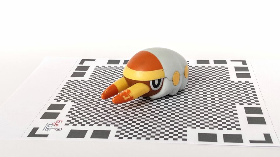
The scanning process is quite fast. You need to place de object over a checkered mat, that can be printed at any size. Then, a dome appears in the phone covering the object to scan. You need to move the camera, so sections of the dome go from translucent blue to transparent. Once done, the app calculates the mesh. It gives you the chance to re-scan the object in other position, to further improve the result.
One of the major drawbacks is that you don't get any info from the bottom part of the object. And if you turn it around completly, chances are that you'll get funny results. But nevertheless, it is really impresive to see what can you get out of a phone... seems that our beloved Star Trek Replicator gets closer every day!!!
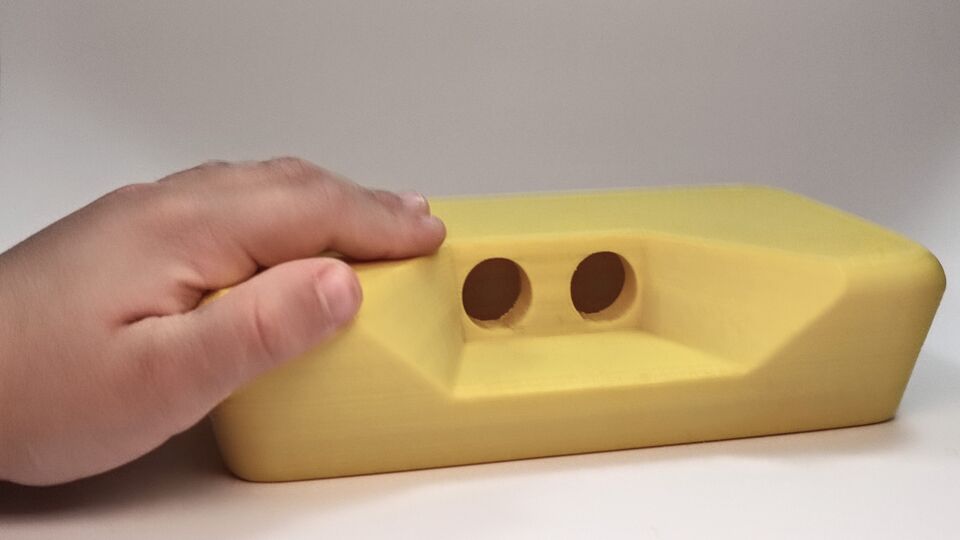
Test case for final project
I could not let pass the opportunity to print out a test case for my final project. And it is great that i did it: the feedback you get of the handling of an object is very valuable. This is what I will have to keep in mind while working in it:
- Size is an issue: too small and it will be difficult to drag accurately, too large and it will be hard to hold it
- Distance from sensor to ends: will make to miss measurements near the corners. Need for keeping it into reasonable
- If it is going to be moved by hand, it is important designing the grip position, so the hand never interferes with the sensors
Definetly, I will consider 3d printing the final prototipe: I am both surprised and pleased with the results, both in finishing and accuracy. I have always seen 3d printing as a last resource technique, due both to failure rate and how time consuming it is. But over the week, I have printed plenty, with very few failed prints (which most of them were due to not using the right nozzle for non-standard materials), and with finishing that in most cases have exceeded my expectations.