13. Networking and communications
This week I learned about networking and communications. I knew that there are so many technologies there. A few words I heard before but the others were new things to me. So I was so interesting and enjoyed myself in this week’s individual assignment.
individual assignment: design, build, and connect wired or wireless node(s) with network or bus addresses
In Group assignment, I worked on Connecting ESP board with the mobile phone with Wi-Fi and documented the Group work in the Group Assignment page.
I2C
Of many technologies explained in the class, I tried to use I2C in my individual assignment per my instructor’s advice.
This is because most simple one is I2C (Inter-integrated circuit).
What is I2C?
” I²C, pronounced I-squared-C, is a synchronous, multi-master, multi-slave, packet switched, single-ended, serial communication bus invented in 1982 by Philips Semiconductor. It is widely used for attaching lower-speed peripheral ICs to processors and microcontrollers in short-distance, intra-board communication. “(Wikipedia)”
These days Salves have another name of “Secondary”.
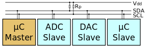
Each box of above illustration is called as Node. Master =issue signals Slave(Secondary) = other receivers
4 cables needed for I2C Communication. - SDL - SCL - VCC - GND
VDD needs Pull Up resister, usually 10k will be enough.
Communication means one device issue signal to convey activation and others receive the signal and do activation as conveyed. If the communication Protocol is the same I2C, peripheral devices can communicate each other.
Individual assignment
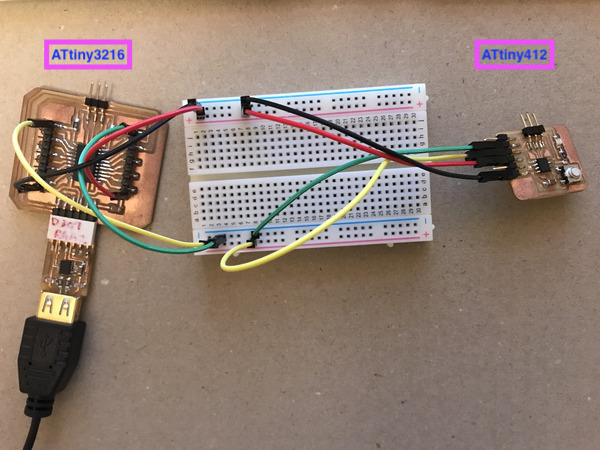
Test 1. Using I2C, communication between ATtiny3216 breakout board and ATtiny412 breakout board.
I will set as ATtiny3216 as Master and ATtiny412 as Secondary.
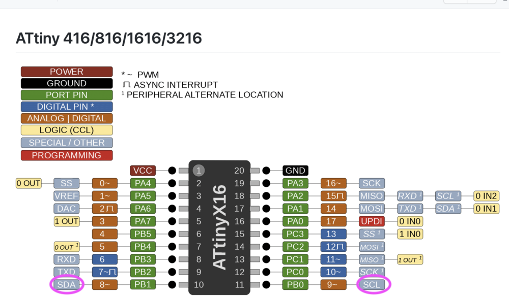
Before starting wiring, I have confirmed the Pinout map of the boards.
I should use PA1 for SDA and PA2 for SCL.
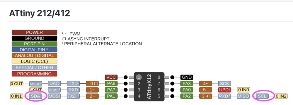
I should use PB1 for SDA and PB0 for SCL.
Then wiring. I used Green jumper code for SDA and Yellow for SCL.
Code for communications between the two boards, I used Examples which are available in Arduino IDE.
After verifying code for each board respectively, then uploaded.
The codes to send “Hello” from ATtiny412 to ATtiny3216.
The results of this can see in Serial Monitor of ATtiny3216.
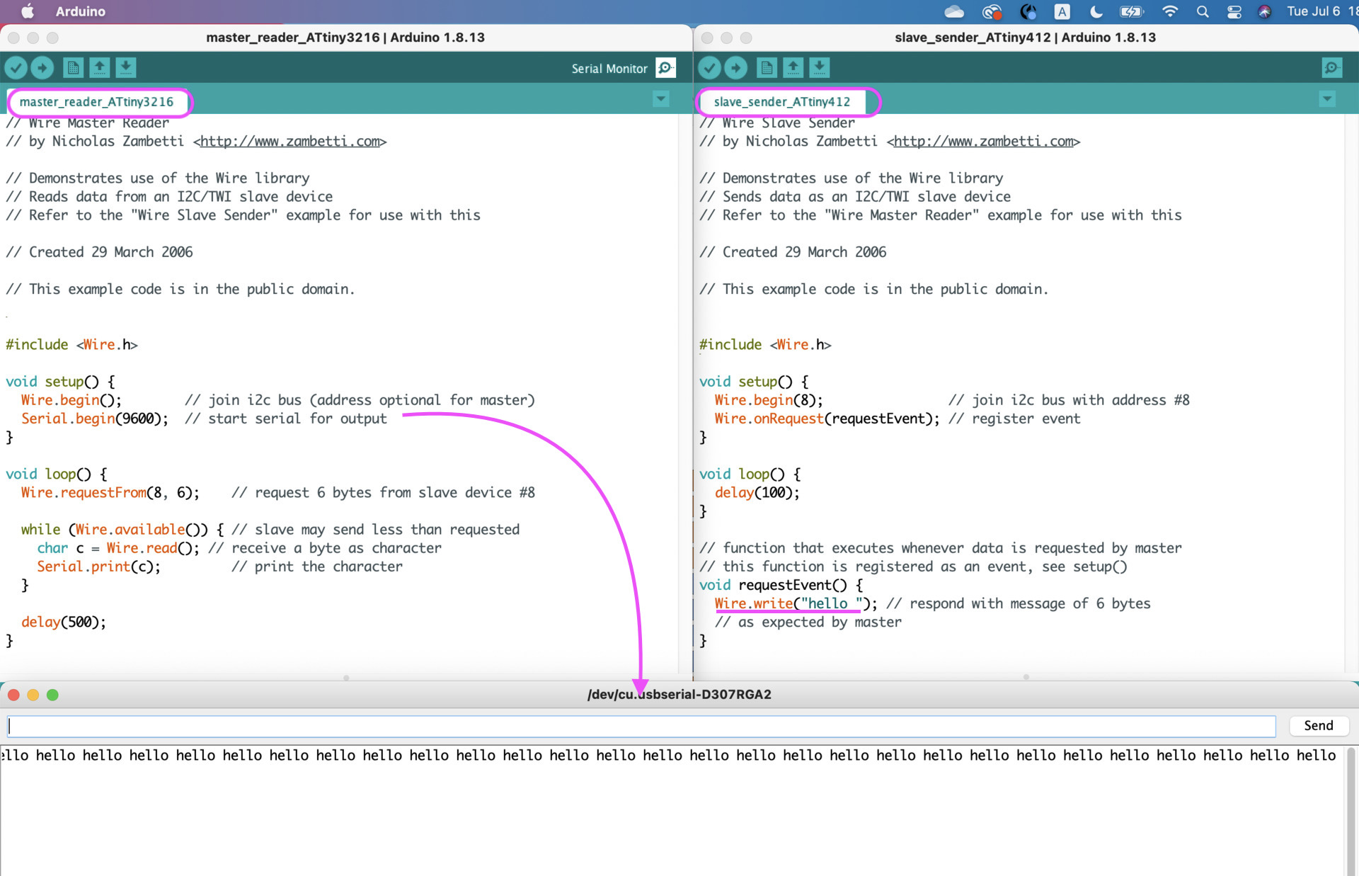
ATtiny412 successfully sent “hello” to ATtiny3216.
Test 2. Using I2C, communication between Attiny 3216 breakout board and OLED.
- OLED: Small display. 128x64 pixel. approx. 3cm Display communication status for debugging
-
Resister location can be changed Usually IIC 0x78 (can see backside of a OLED part. - should use 0x3C for iIC(Wire library). Removing last single digit means hexadecimal.
-
Library install required
Install libraries-> Arduino IDE > Tool > Manage Libraries - Adafruit SSD1306 ver. 2.4.4 - Adafruit GFX-Library ver. 1.10.7 - Arduino manage library Adafruite SSD1306
-
Cabling OLED to Attiny 3216 breaout board
PB0 and PB1 of t3216 can use
- Attiny 3216
Default : SDA=PB0 ,SCL=PB1. <— my breakout board has pull up resisters to these.

If needed, we can swap to SDA1 and SCL1 when OLED has pull up resters as preset.
- Program
I referred an example which is available in Arduino IDE and made adjustments.
The example can be found below.
-
Arduino IDE > File > Examples > Adafruit SSD 1306 > ssd1306_128x64_i2c
-
Adjuistemnts the line around line no:35
- Before
#define SCREEN_ADDRESS 0x3D - After
#define SCREEN_ADDRESS 0x3C
- Before
