6. Electronics design
This week I worked on preparing PCB starting from circuit design to soldering and then tested it.
Individual assignment : - redraw an echo hello-world board, - add (at least) a button and LED (with current-limiting resistor) - check the design rules, make it, and test it - extra credit: simulate its operation
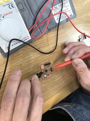
I worked on wiring hello.USB-serial.FT230x,RX(Receiver) and TX(Transmitter) for checking with oscilloscope. Also played as a camera woman for recording the group work.
Redraw an echo hello-world board - using EAGLE
- Selected ATtiny412 for UPDI
-
EAGLE setup Import necessary libraries to EAGLE from Kannai instruction site and copy from managed libraries of EAGLE. Change “View” to de-select bottom four panels to have better workspace for Schematic and Board respectively.
-
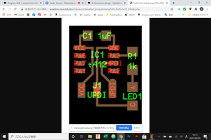
Placed parts tentatively and assign values to capacitor 1uF, and resistor 1k.
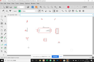
- Decided which pin of ATtiny412 to connect LED and button. Considered spaces, decided to assign Pin 7 to LED and Pin 6 to button. Chosen pin available for PWM to blink LED a bit slowly.
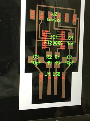
- Schematic In order to avoid complication of presentation put GND at ends.
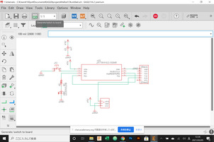
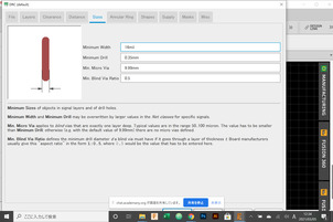
- Design Rules : Set clearance as 16mil and size minimum width 16mil as well. Check errors by ERC.
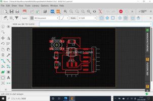
- Then switch to Board view and drawing connections. This process was solving a sort of PUZZLE! Although it was looking OK, I got warning / errors in DRC.
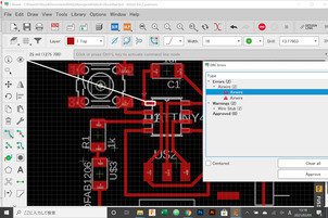
- My drawing. There are some narrow paths. Let’s see if milling goes well or not…
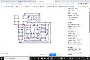
Make it - using Fab module and MDX-15.
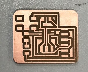
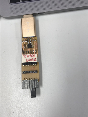
- Narrow path successfully milled.
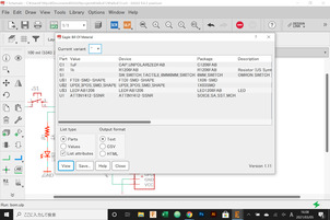
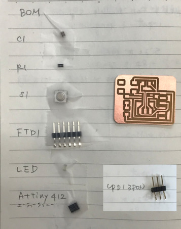
Pick up parts per BOM
Two weeks ago, I lost a part. I learned better way of handling parts in the review and replicated. The parts were put on notebook with tape.
soldering , then testing PBC
Carefully soldering. I think I could do it much better than before.
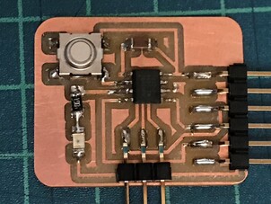
Examination of connections. No errors found.
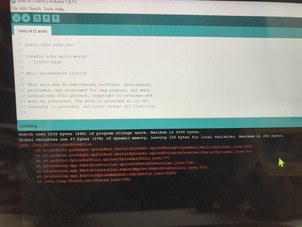
Arduino IDE imported code and upload it thru Powershell to my PCB
Due to encountering errors, used Powershell for uploading codes.
Test 1 - Echo test.
Pins to cap. RX inflow - TX outflow
Capped to have echo.
Echo back
Test 2 - LED and button
Successfully flashed when pushed button
Files
-png
Arduino IDE files
-echo
-simpleblink