12. Output Devices
1. Group assignment.
1. Measure the power consumption of a small 28byj48 stepper-motor
We needed to use 2 of those in an object I am making, that has to move around. We connected both and put the multimeter in between the power line to measure the current going through.
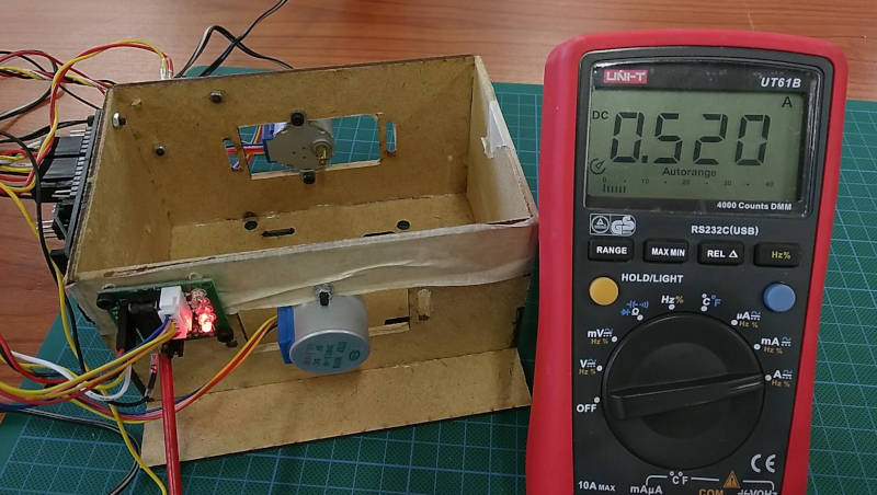
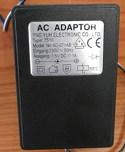
This measures around 520mA, which is in line with the datasheet. The datasheet tells us such motor would draw around 240mA each. This is setup was powered by a 7.5V DC/1A wallwart power supply.
We can now calculate Power consumption in Watts with the following formula:
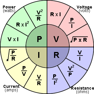
P = V x I → P = 7.5V * 0.520A = 3.64 W
2. Measure vibration motor
For our final project we would need the vibration motors like in a cellphone to make our pager puck vibrate. To figure out if we can run them on the 3.3V lipo battery we want to use and if we could directly power them from the output pins of the ESP8266. We hooked on up to a lab powersupply and measured how much current it needs to run.
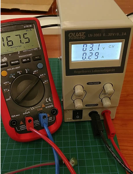
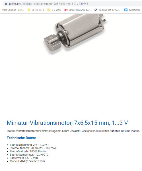
We gave the motor around 3V DC to run smoothly. The current output of the PSU was set around 0.3 A. With the multimeter connected in series between the power source and the motor we saw that it actually uses 167.5 mA. The motors we have, we don’t find the details of them anymore. But we looked up something similar from the same supplier. We think ours are a somewhat older and also less efficient.
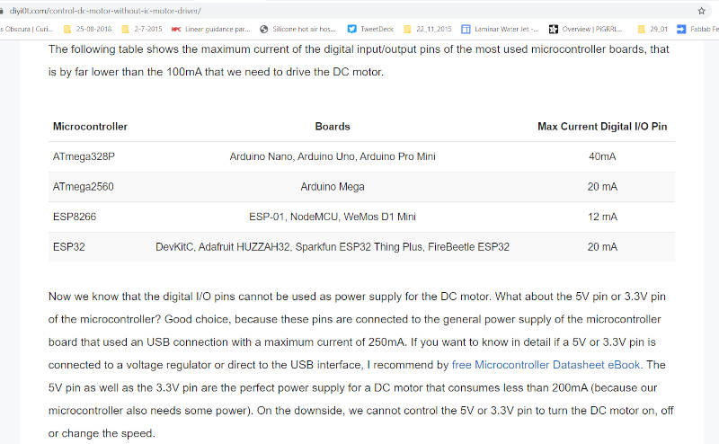
On this website https://diyi0t.com/control-dc-motor-without-ic-motor-driver/ we found the esp8266 only supplies 12mA on the digital output pins. That will definitely need a transistor or a mosfet to control the vibration motor.
2. testing some output devices
1. piezo speaker making tones
For this exercise it put a small piezo speaker to a digital output pin of my board. The piezo speaker uses little power and can be powered directly for the microcontroller output pin. I used the board I re-made for the input week.
I connected the speaker to pin 16 of the Esp and the GND lead to GND. I wrote a few simple lines of code to use the TONE command in Arduino to generate some random sequence of tones between 120 and 800 Hz.
int speakerPin = 16;

void setup() {
  // initialize serial communications (for debugging only):
  Serial.begin(9600);
  randomSeed(analogRead(A0));
}

void loop() {
  // make random not in the output pitch range (120 - 1500Hz)
 int thisPitch = random(120, 800);
 Serial.println(thisPitch);
  // play the pitch:
  tone(speakerPin, thisPitch, 500);
  delay(100);
}
2. little vibration motor
the little vibration motor also needed a test to control it from the ESP. I don’t have the SMD mosfet needed, so I made up a little breadboard test to see if this could work. When it works I can order the smd components to incorporate in the final project pcb. I used a TIP120 Darlington transistor from my partsbin for this test
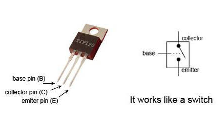
and connected it as shown in the illustration
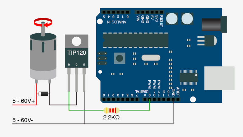
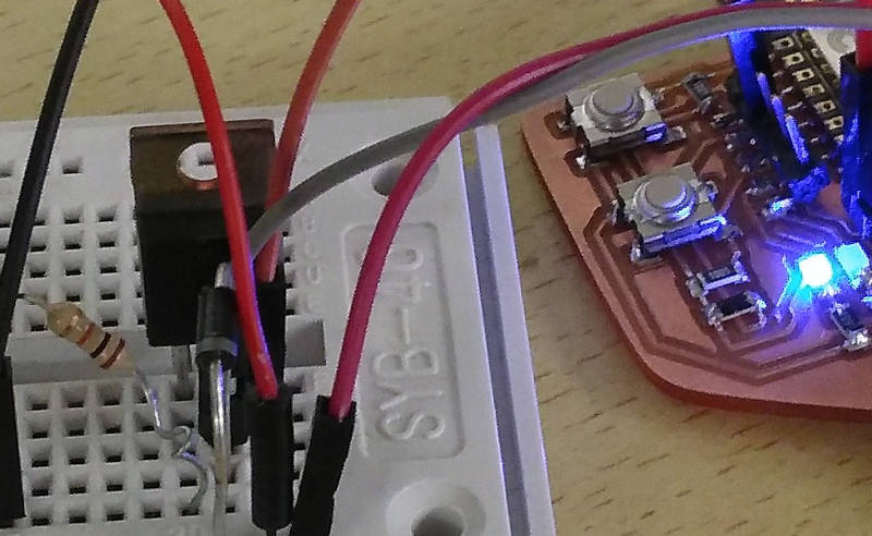
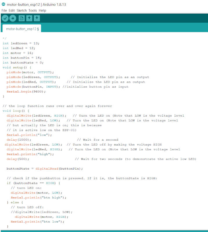
I added some extra code to my button/led test code from input week. To connect the motor to pin 16 as an output. I added code that the motor stops when the button is pressed and turns when it is released.
3. 7 segment display
We will probably also need a display for our final project. So I thought to try out a 7 segment module I had lying around.
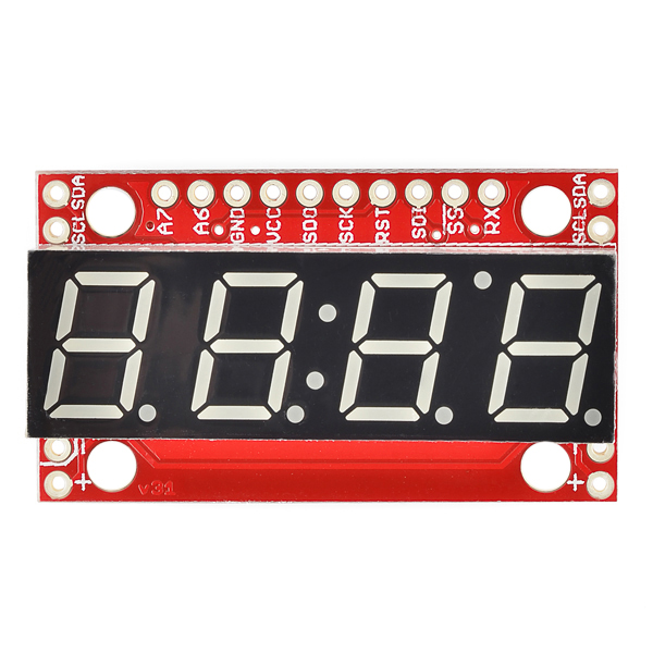
It is a sparkfun module https://www.sparkfun.com/products/11441. The sparkfun page also has lots of information on the module. Such as the pinout and how to use it https://learn.sparkfun.com/tutorials/using-the-serial-7-segment-display
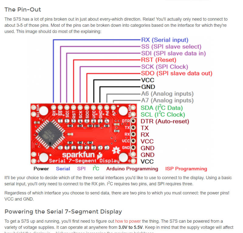
I wanted to use this module with the I²C protocol. It would be handy to have different inputs or outputs on this bus system. To limit the amount of IO pins needed on the MCU.
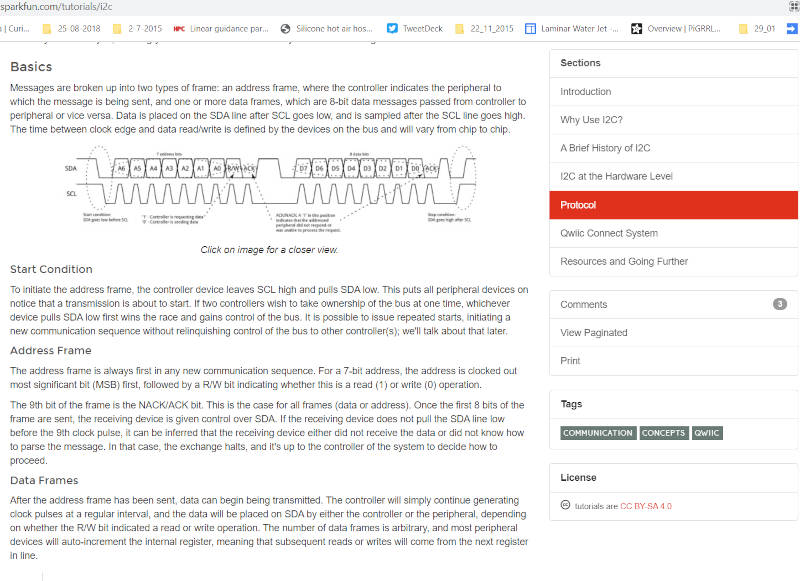
Sparkfun also has a tutorial page on I²C: (https://learn.sparkfun.com/tutorials/i2c)[https://learn.sparkfun.com/tutorials/i2c] It explains the pros and cons and how it actually works
After connecting the display to my board and uploading some basic test code. I got strange results. I think the output power of the ESP module is not strong enough for this module. I did use those with arduino on a 5V system and that worked. But the ESP is 3V and also the pins output much less current. I have to test this some more to see what makes this not work!
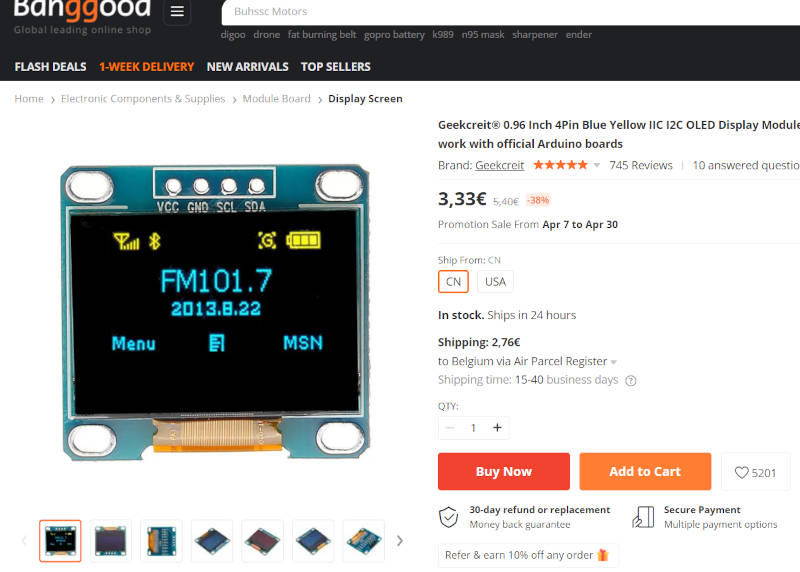
4. little oled display
I also have a cheap little 128x64 oled display, that works on I²C. So let’s give this a try also.
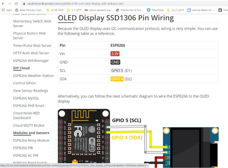
On the randomnerdtutorials website I found info on how to connect and program this display.
https://randomnerdtutorials.com/esp8266-0-96-inch-oled-display-with-arduino-ide/
It also has a nice little script to find out what address your I²C device uses, so you can adjust your code to talk to the correct device. https://raw.githubusercontent.com/RuiSantosdotme/Random-Nerd-Tutorials/master/Projects/LCD_I2C/I2C_Scanner.ino
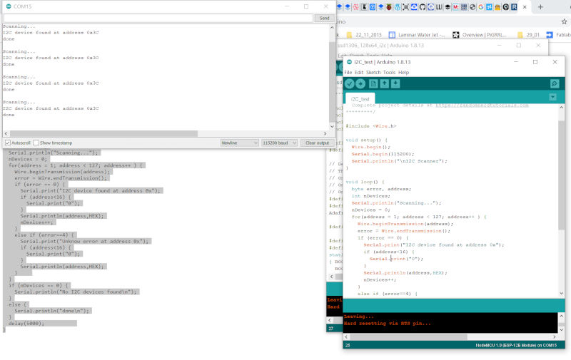
After finding the address. I made something to display a ‘hello Kurt’ and some random generated circles on the screen. This worked like a charm. It makes use of de adafruit libraries for de SSD1306 drivers used in these displays and a graphics library.
#include <Wire.h>
#include <Adafruit_GFX.h>
#include <Adafruit_SSD1306.h>

#define SCREEN_WIDTH 128 // OLED display width, in pixels
#define SCREEN_HEIGHT 64 // OLED display height, in pixels

// Declaration for an SSD1306 display connected to I2C (SDA, SCL pins)
Adafruit_SSD1306 display(SCREEN_WIDTH, SCREEN_HEIGHT, &Wire, -1);

void setup() {
  Serial.begin(115200);

  if(!display.begin(SSD1306_SWITCHCAPVCC, 0x3C)) { // Address 0x3D for 128x64
    Serial.println(F("SSD1306 allocation failed"));
    for(;;);
  }
  delay(2000);
  display.clearDisplay();
  display.setTextSize(1);
  display.setTextColor(WHITE);
  display.setCursor(0, 20);
  // Display static text
  display.println("Hello, Kurt!");
  display.display();
}

void loop() {
  delay(2000);
  display.clearDisplay();

  display.setTextSize(2);
  display.setTextColor(WHITE);
  display.setCursor(10, 30);
  // Display static text
  display.println("Hello,");
  display.display();
   delay(2000);
  display.clearDisplay();

  display.setTextSize(3);
  display.setTextColor(WHITE);
  display.setCursor(30, 20);
  // Display static text
  display.println("Kurt!");
  display.display();
     delay(2000);
   display.clearDisplay();

  for(int16_t i=0; i<max(display.width(),display.height())/2; i+=2) {
    display.drawCircle(random(display.width()), random(display.height()), 10, SSD1306_WHITE);
    display.display();
    delay(1);
  }

  delay(2000);
}