7. CNC big stuff
1. Group assignment
1. Safety
Our big router table is a RivaCnc 2400. It has a workbed of 2400x1200 mm with vacuum table.
The frequency controlled spindle has a max rpm of 24000
This is a big and powerful machine. Before using the machine you need an instruction session and read the manual first.
 We don’t have any laser curtain or fence around it, so always be extra careful.
Needed personal protection are:
- safety shoes
- safety glaces
- ear caps for the noise.
- Never have any loose clothing or hair when operating machines with fast moving parts!!!
![]()

-
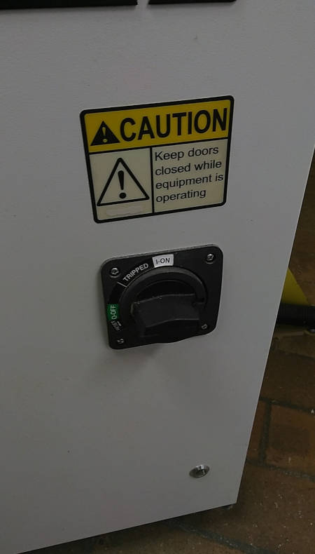
Know where to find the emergency stop!
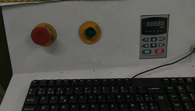
-
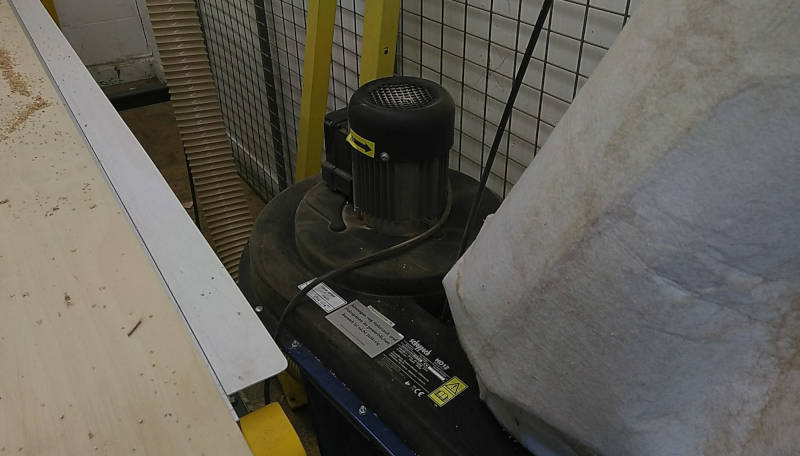
And you can start the dust collection on the back.
2. Controlling the milling machine.
The RivaCNC is controlled by USB-CNC control software on the dedicated pc. This software expects ISO G-code.
To create the toolpaths and g-code we use VCarve pro software. This is a very nice software that imports pdf, ai, svg or dxf. It can also import 3D formats of images.
You can do a lot of adjusting and design inside this software as well.
Inside the VCarve we also keep a tool database, you can select a tool while creating a toolpath.
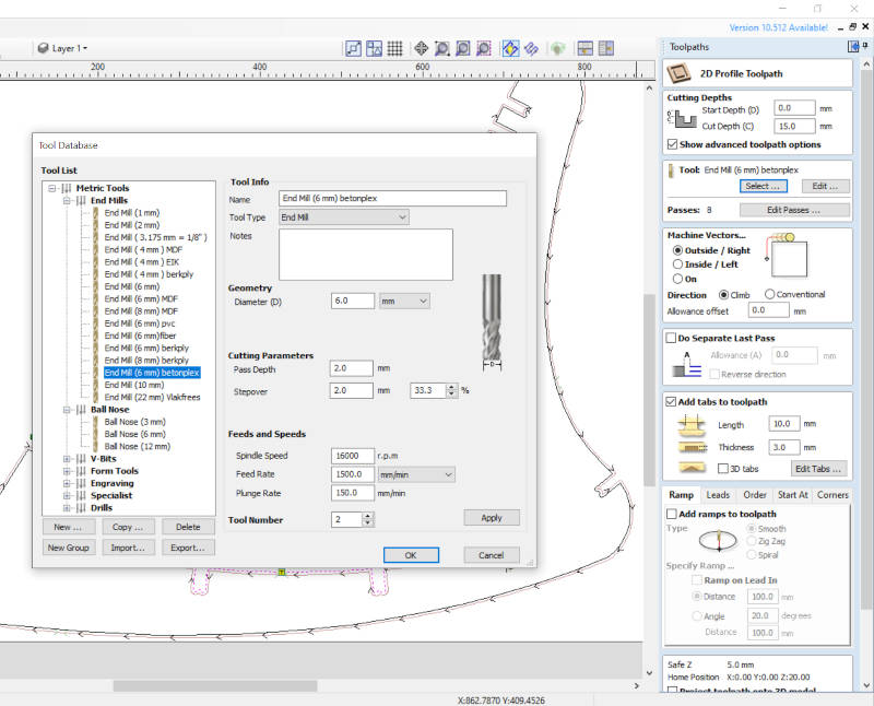
For this excerise we will mostly use 2D-profile toolpaths. You can select the lines in the drawing and adjust the toolpath parameters.
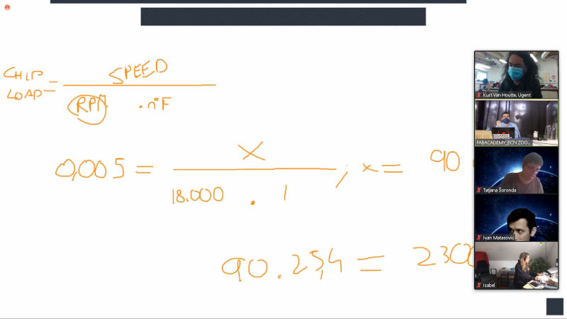
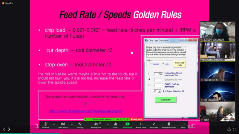
In class we had an explanation on how to choose speed and parameters.
3. preparing the machine
- turning the machine on with the big power switch. And the green pushbutton to start up.
-
fixing material with clamps, make sure the material stock is tightly fixed. Stock that gets loose while milling can be dangerous and will result in destroyed parts.

-
inserting the right endmill, also make sure it is fitted correctly and tight. Loose milling bits are even more dangerous.
-
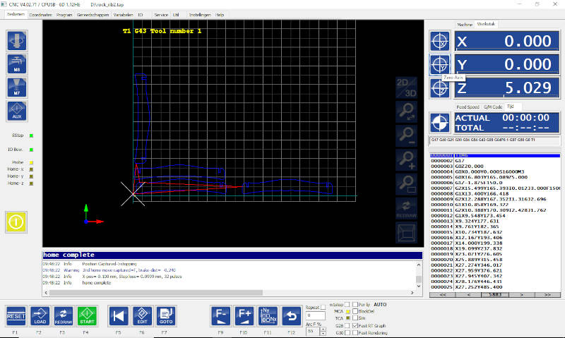
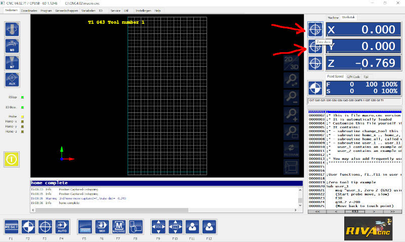
homing the machine, firsts click the homing button. The machine will move to the home posisition.

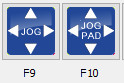
- Now move the toolhead to the place you want to start, by jogging the X and Y. Use the buttons or the arrows on the keyboard.
-
setting XY zero
-
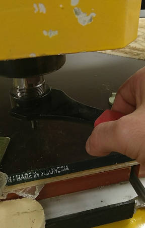
setting Z zero, take the sensing tool and place it under the milling bit.
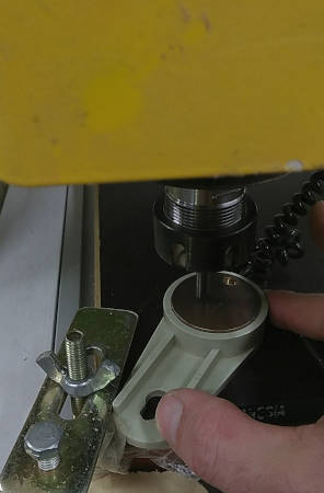 In the software go to the user menu (F11) and click the Z-zero function (F2). This moves the milling bit down up to the sensor and registers that point as zero.

-
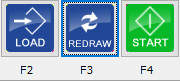
load G-code files, press the auto button (F4)
 Next press the load button (F2) to select the g-code file you want to mill.

-
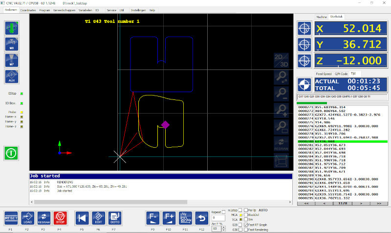
start cutting, press start (F4)
 Job started! You will see the spindle getting speed and the head moving. On the screen you can follow the movement of the machine and also in the g-code on the right you can see what commands are getting executed.
2. Design and make something big
This week I still had to finish my pcb board, because I got some problems first with designing the traces and then with getting it milled correctly. I had to wait for the good endmills to arrive while trying other alternatives. And also I had lots of machines in the lab to fix and repair this week. So not that much time left to design and build big things.
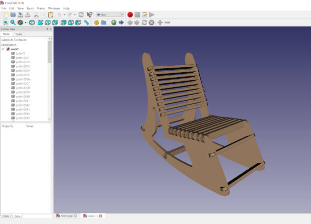
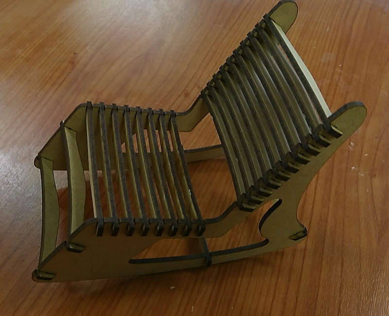
I have already some experience cnc milling big things, like this rocket I made for one of my sons ![foto raket viggo]. To save some time I decided to make a rocking chair I once designed as an excercise to learn myself working in FreeCad. I still have the drawing, but never actually made it.
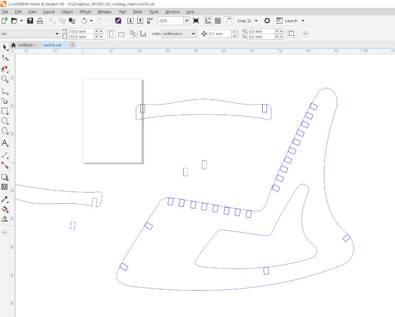
So I exported the parts to adjust and finalise the milling part in Coreldraw. I mostly use 2D software to design things for 2D cnc milling or lasercutting. So I went this route again. In my FreeCad drawings I had used simple slots to fit the parts together. Now in Coreldraw I added the dogbone style cutouts to make the parts fit better after milling.
Before making something big it is never a bad idea to try it out on a smaller scale ;-)
So I also scaled down the drawing to make a prototype in 3mm Mdf on the lasercutter.
doing this enables you to see the design in real and look and test if everything is as you want it
and this is the result of the laser cutting
Here i saw I maybe needed to add some ribs in the bottom to make it more sturdy. I was going to us the same rib everywhere, but here I also noticed that the bottom rib has to be thinner. Now it touches the floor. So for this rib I have to make an adjusted shape.
Once the design was good I exported it as pdf in Coreldraw to open it up in Vcarve Pro. Here I can make some adjustments and also cut out the slots and drew a test piece to try out the pressfit.
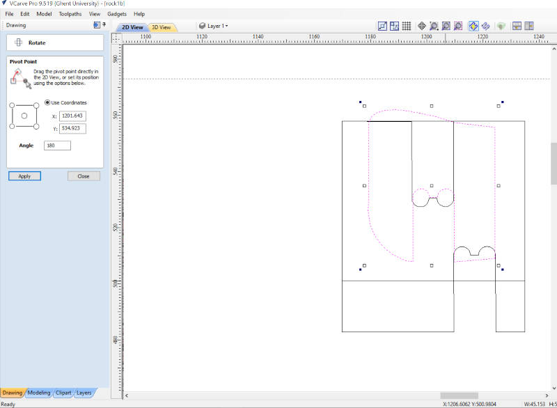
Normally now I can just select all the curves and make them into a 2D profile toolpath. But this time I got some errors, I never got before.
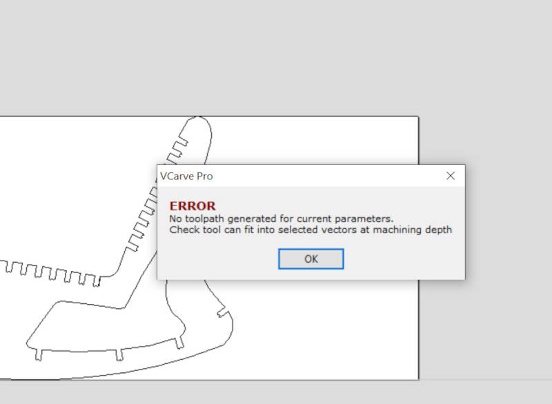
I’m using a 6mm endmill and I get the error that the tool can not fit into the selected vectors. Weird! All spaces are bigger than 6mm, also the dogbones. What could be causing this error? I tried all kind of different things. I first thought I had to make the dogbones bigger. But when I choose a 2mm endmill I still get the same error.
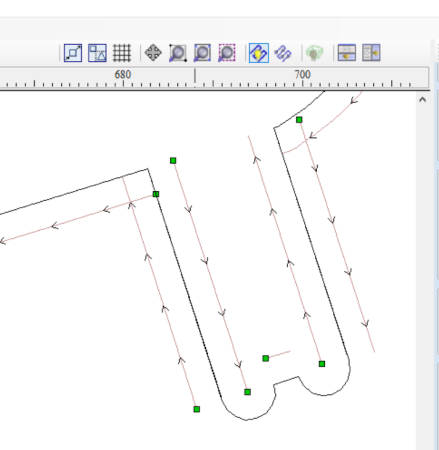
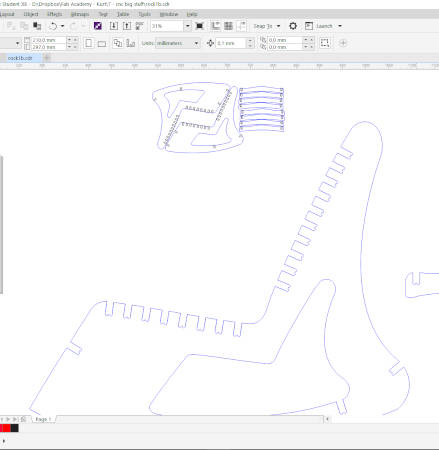
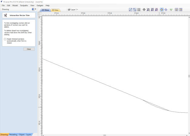
Here you can see that the parts where there is a toolpath made, after ignoring the error. You see the lines are not continuous.
Before making the toolpath I first got to join all of the lines to be able to create a toolpath. So maybe there went someting wrong there? After lots of looking over the drawings, and zooming in on places where the joints where made. I had to really zoom in big to notice the reason why this errors kept coming up.
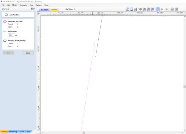
Some places had lines not connecting, but they where like 0.001mm apart. Not able to see when you look at the drawing, except when you extremely zoom in. Also in some parts there where double lines next to each other. So I had to go over the whole design in very close detail and fix those errors. In the end I had a cleaned up drawing and no more errors when I generate the toolpath. yeay!
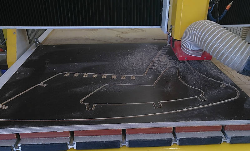
3. Milling the Parts
On to the actual milling. :-) First we do some test pieces to see the fit and where we need to compensate.
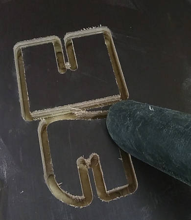
 The 2 parts slide in eachother very nice and firm.
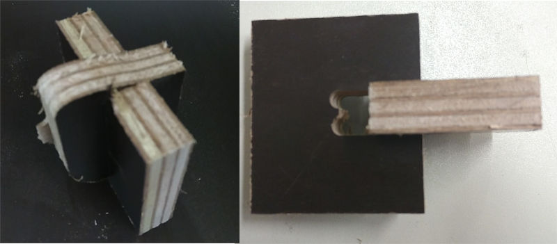
We do some measurements to be able to offset our designs or calculate some compensations for the run-out.
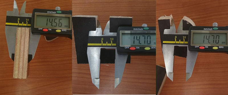 We drew the slots to be 14.8 mm and see there is a 0.1mm runout. We also measured the thickness of the stock. It sells as 15mm thick, but not all plates are the same. This one is only 14.56mm thick.
Since I am going to mill the parts out of different left-over pieces of plywood. The thickness will vary a bit.
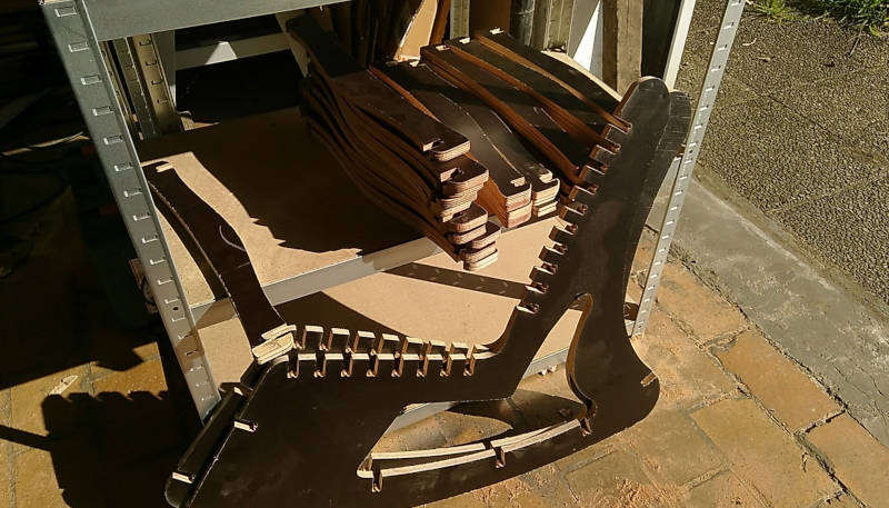
Milling the Parts
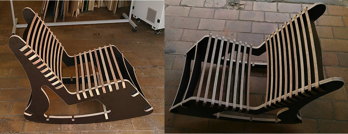
 Final chair
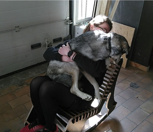
 First test by Mysa and Isabel
The heroshot movie :-)