8. Embedded programming
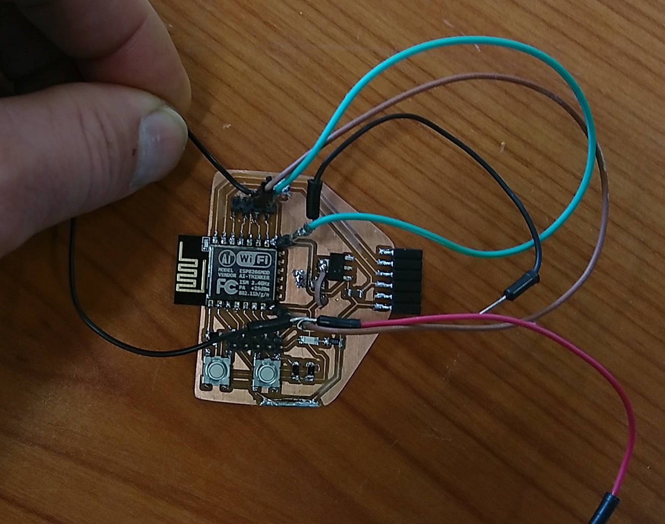
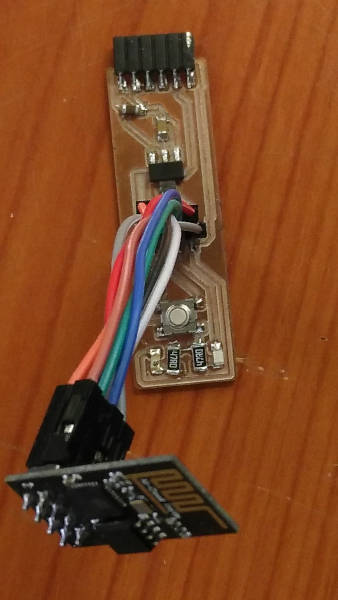
Getting my esp-board programmed.
The first board I did, I couldn’t get to connecting to it through the ftdi-board. So not able to program it. I kept trying all kinds of things, no luck. So I designed a second board. Also no luck. Last week I took a closer look at the first board and the traces. I found out I got some parts connected wrong or didn’t connect them at all. Oops
Reading some microcontroller data ;-)
This week we have to read a datasheet, so I thought I could look into some details of the esp8266/ESP-01. Maybe I can figure out how to get my board programmed. I wanted to use this, because in the end I would like to use ESP32 module for the final project, but wanted to start smaller and had some of these older ESP-01 (https://www.sparkfun.com/products/17146) lying around. This board was one of the big boosters of the DIY IOT(internet of things).
Sparkfun had also a nice graphical datasheet
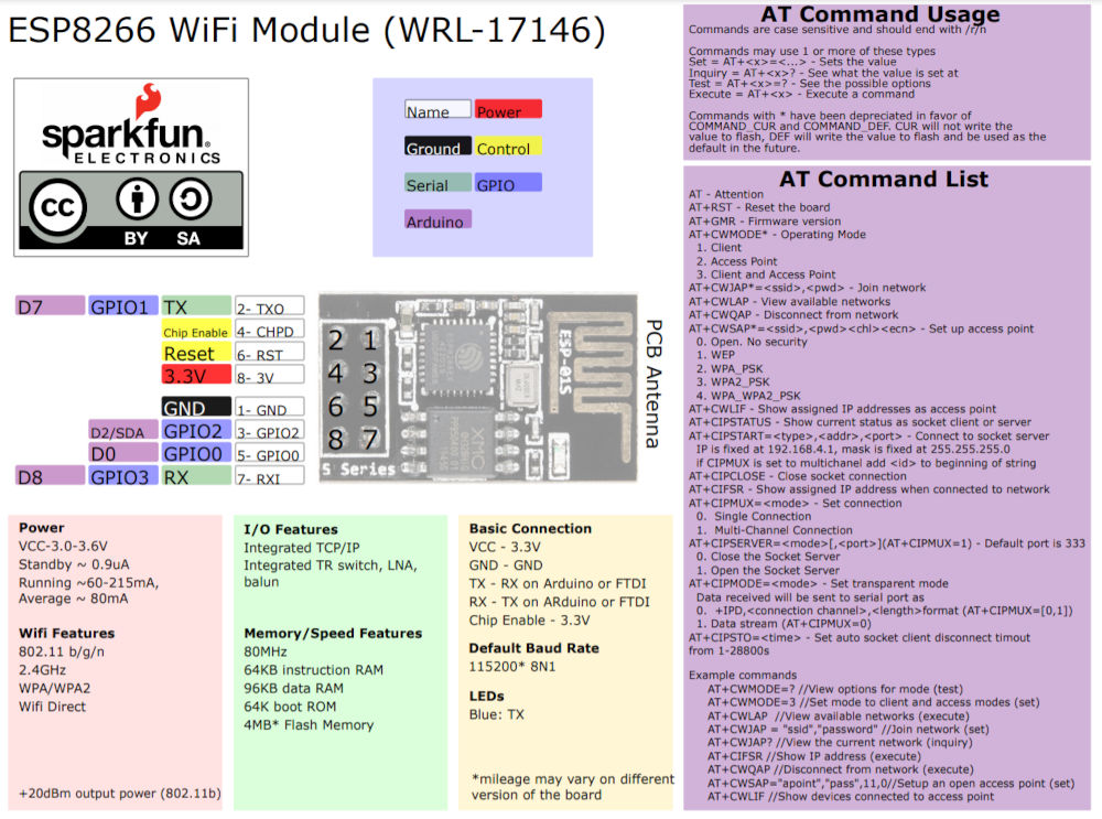
First I went to see on the espressif website https://www.espressif.com/en/products/modules/esp8266, if I could find a datasheet. I could find the datasheet of the esp8266 SOC(system on a chip), that is the main chip used in the ESP-01 module
key features :
- Built-in low-power 32-bit RISC CPU: can double as an application processor
- low power consumption
- 802.11 b / g / n
- Wi-Fi Direct (P2P), soft-AP
- Built-in TCP / IP protocol stack
- Built-in TR switch, balun, LNA, power amplifier and matching network
- Built-in PLL, voltage regulator and power management components
- 802.11b mode + 19.5dBm output power
- Built-in temperature sensor
- Support antenna diversity
- off leakage current is less than 10uA
- Built-in low-power 32-bit CPU: can double as an application processor
- SDIO 2.0, SPI, UART
- STBC, 1×1 MIMO, 2×1 MIMO
- A-MPDU, A-MSDU aggregation and the 0.4 Within wake
- 2ms, connect and transfer data packets
- standby power consumption of less than 1.0mW (DTIM3)
Most important for us to keep an eye on:
- Only uses 3.3V → so be carefull not to connect 5V ftdi. This is also why I added the 3.3V regulator to the board.
- also the GPIO pins use and give 3.3V
- Serial RX/TX pins are available
- Only 2 extra GPIO pins are available
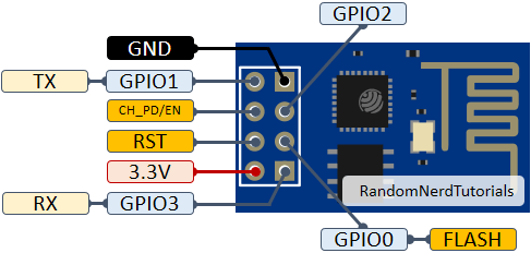
I found a lot of information on this randomnerdtutorials website.
They had a nice overview of modules and pinouts like this one of the
Meanwhile I also found a couple of things that I needed to check to maybe still be able to program my second board.
- the ftdi header was also upside down. So i have to connect the ftdi board facing down instead of up. But that was an easy fix
- I had my 8pin header on backwards, so I fixed this by connecting the ESP-01 with jumper wires to the right headerpins on my board
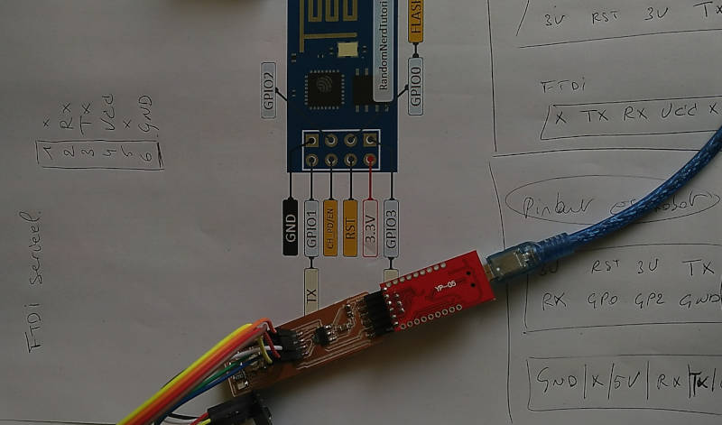
- CH_PD/EN pin should always be 3.3V → this pin actually enables the chip to run.
-
GPIO0 pin should be brought to GND to be able to program the chip
-
Since my board has also the LED connected to that pin. That was what made it impossible to program it. So for programming I disconnect the wire and connect the pin to GND
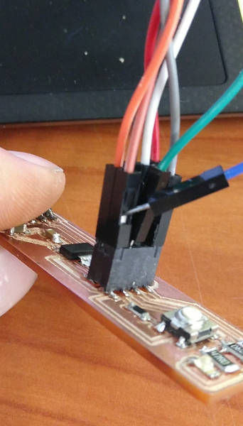
- You need hard reset while the software tries to connect. Also you need hard reset to start the uploaded code. → My board doesn’t have a reset button, so I have to disconnect it briefly
Get some code running!
1. Arduino
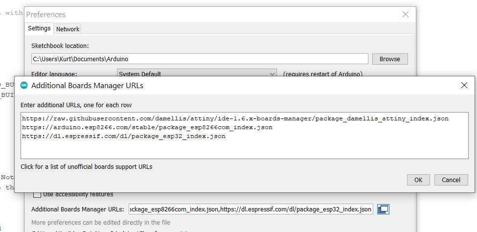
To start I want to use something familiar, to see it actually works Before being able to use the ESP board with arduino I needed to install some new boards and example files with the boardmanager Add this URL:
http://arduino.esp8266.com/stable/package_esp8266com_index.json
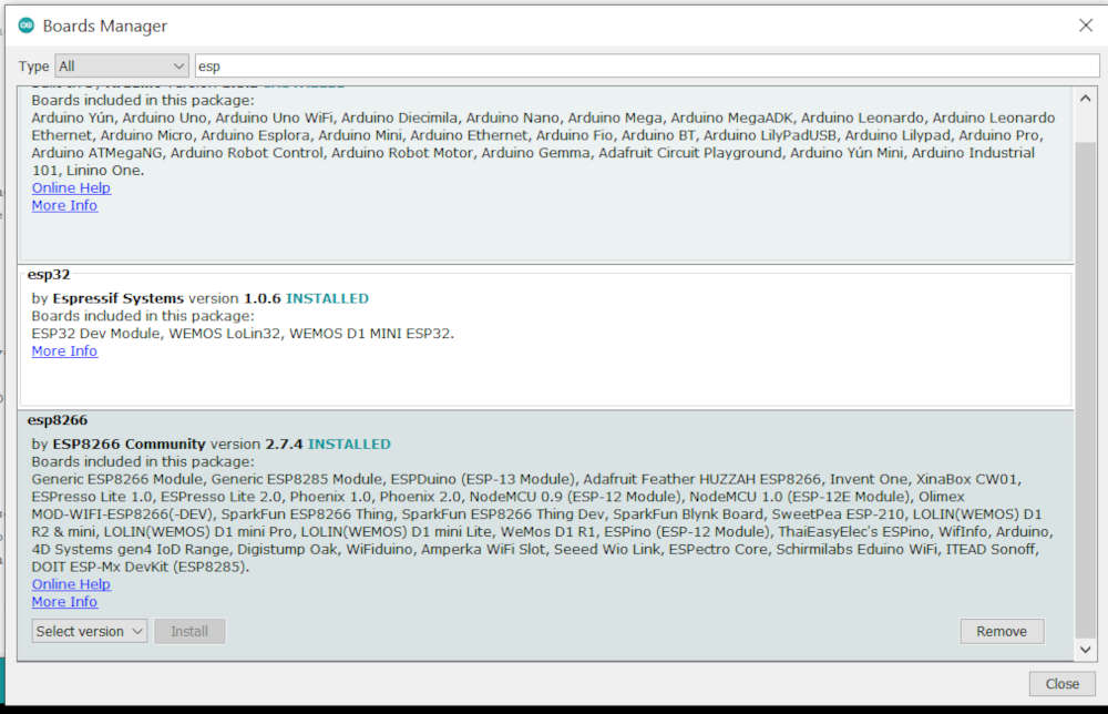
Now you can go to TOOLS→board and select Generic ESP8266 module from the list of ESP8266 boards.
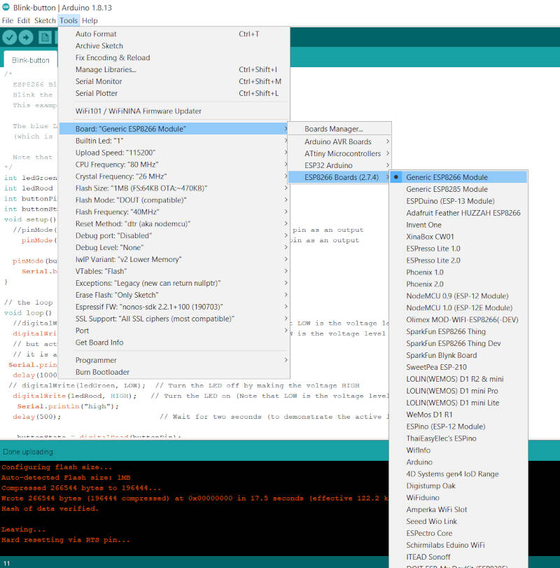
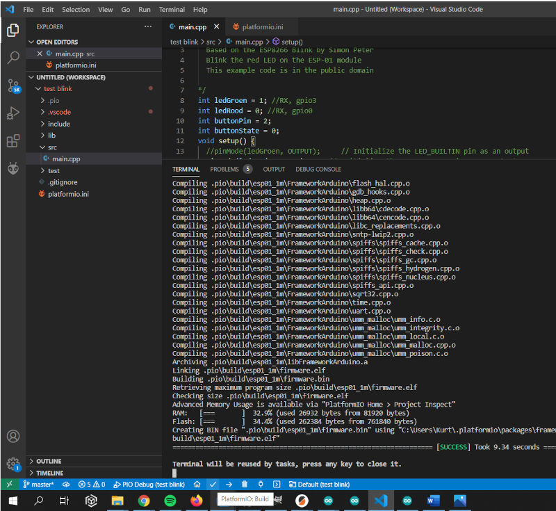
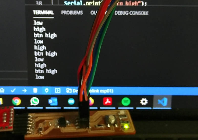
For the code itself, I took the blink example and modified it a bit. Besides making the LED blink, I also wanted to test the button and send some feedback to the pc through the serial RX-TX pins.
/*
  Based on the ESP8266 Blink by Simon Peter
  Blink the red LED on the ESP-01 module
  This example code is in the public domain

*/
int ledGroen = 1; //RX, gpio3
int ledRood = 0; //RX, gpio0
int buttonPin = 2;
int buttonState = 0;
void setup() {
  //pinMode(ledGroen, OUTPUT);     // Initialize the LED_BUILTIN pin as an output
  pinMode(ledRood, OUTPUT);     // Initialize the LED_BUILTIN pin as an output
  pinMode(buttonPin, INPUT);
  Serial.begin(9600);
}

// the loop function runs over and over again forever
void loop() {
  //digitalWrite(ledGroen, HIGH);   // Turn the LED on (Note that LOW is the voltage level
  digitalWrite(ledRood, LOW);   // Turn the LED on (Note that LOW is the voltage level
  // but actually the LED is on; this is because
  // it is active low on the ESP-01)
  Serial.println("low");
  delay(1000);                      // Wait for a second
  // digitalWrite(ledGroen, LOW);  // Turn the LED off by making the voltage HIGH
  digitalWrite(ledRood, HIGH);   // Turn the LED on (Note that LOW is the voltage level
  Serial.println("high");
  delay(500);                      // Wait for two seconds (to demonstrate the active low LED)

  buttonState = digitalRead(buttonPin);

  // check if the pushbutton is pressed. If it is, the buttonState is HIGH:
  if (buttonState == HIGH) {
    // turn LED on:
    digitalWrite(ledGroen, LOW);
    Serial.println("btn high");
  } else {
    // turn LED off:
    digitalWrite(ledGroen, HIGH);
    Serial.println("btn low");
  }
}
video of led blinking, button press and serial monitor
2. C en makefile
I already have the gcc, make toolchain installed from previous lessons. So I thought I should also try to make the LED blink with a C file through those commandline tools I went to see some info here https://github.com/esp8266/esp8266-wiki/wiki/Building I still want to try this, when I have more time
3. PlatformIO en vscode
I never used the platformIO and since they say good things about it. I thought I try to install the toolchain and see if I could also get this working. I got doubts to use Atom as IDE, but I did use Visual Studio code a while a go and thought it would fit better. So I went to the platformIO website to follow the instructions and setup this environment. https://docs.platformio.org/en/latest/integration/ide/vscode.html This was pretty straightforward:
        1. Open VSCode Package Manager
        2. Search for the official platformio ide extension
        3. Install PlatformIO IDE.
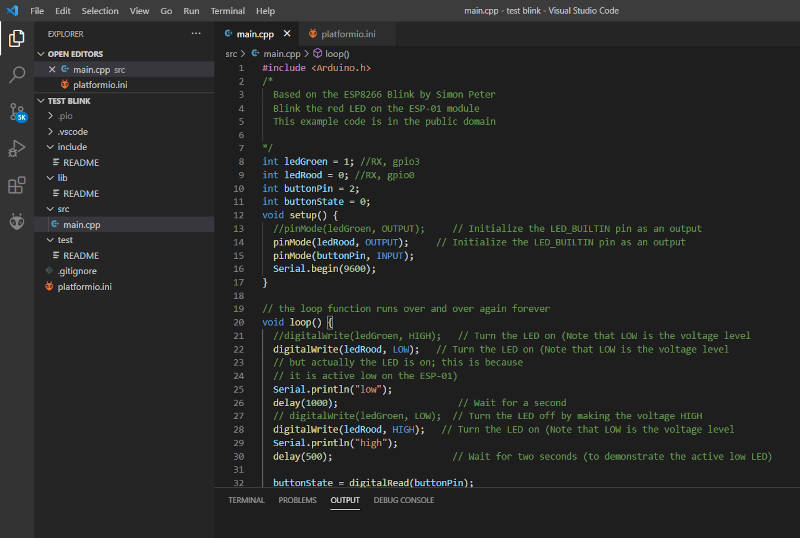
I followed the introduction tutorial and quickly could setup a blink example To start a new project, it is easy to use the wizard. You select the board, platform and framework you want to use. You then get a project folder made with all files needed.
In the source folder there is an empty main.cpp, this is where you can put your code. I used the same code as before.
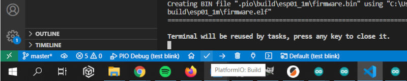
Once the code is complete you can build it using the ‘check mark’ icon in the toolbar and then upload it using the ‘arrow’ icon.
Useful short-cut keys
ctrl+alt+b / cmd-shift-b / ctrl-shift-b Build Project
cmd-shift-d / ctrl-shift-d Debug project
ctrl+alt+u Upload Firmware
ctrl+alt+s Open Serial Port Monitor
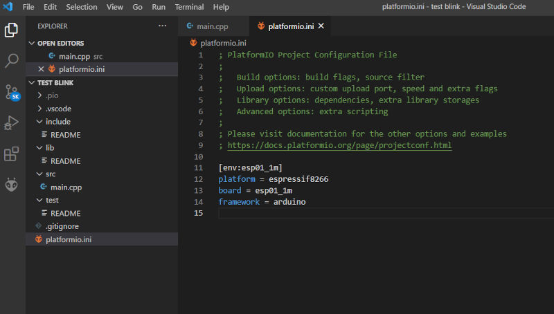
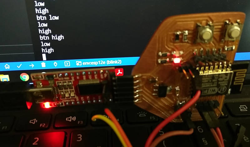
I also tried programming my ESP-12 board, I made for the input week, with the platformIO. This means making a new platformio.ini file with the right settings for this board.
[env:esp12e]
platform = espressif8266
board = esp12e
framework = arduino
I reused the same code as for the esp01 board, had to adjust the pins for this one.
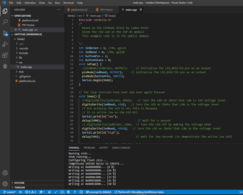
This worked good to compile and upload the code
4. MicroPython
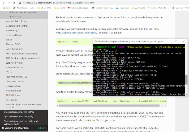
I tried installing and running MicroPython on my ESP-12 board. I followed the tutorial on this website http://docs.micropython.org/en/latest/esp8266/tutorial/intro.html
- you need first to download the right firmware for your board. http://micropython.org/download/esp8266
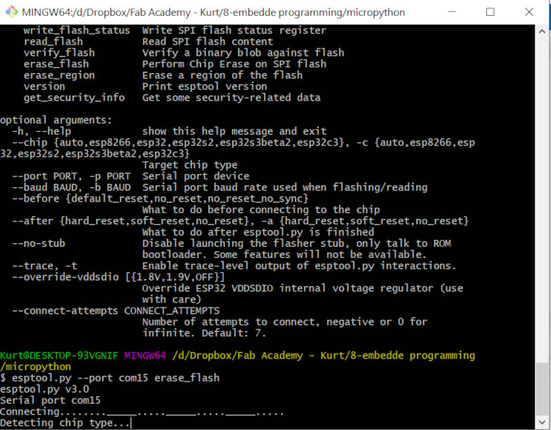
- Then install esptool.py to copy across the firmware. You can find this tool here: https://github.com/espressif/esptool/, or install it using pip: pip install esptool
- Using esptool.py you can erase the flash with the command: esptool.py –port com15 erase_flash
- And then deploy the new firmware using: esptool.py –port com15 –baud 115200 write_flash –flash_size=detect 0 esp8266-20210418-v1.15.bin
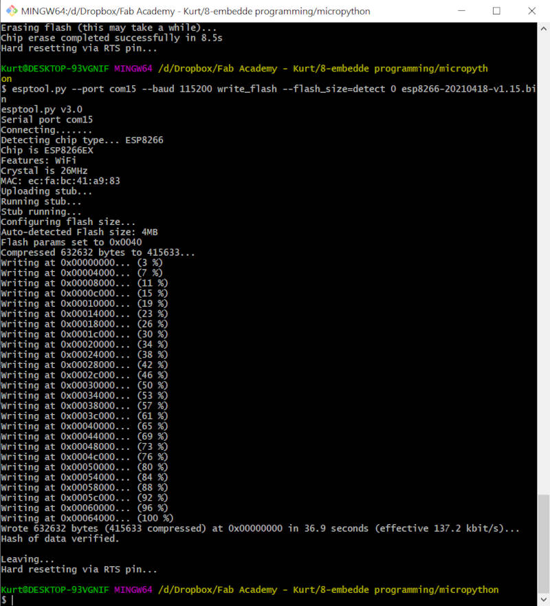
This went all ok without problems
Now you can connect through WIFI, or program the board with python code
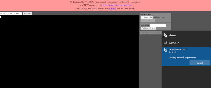
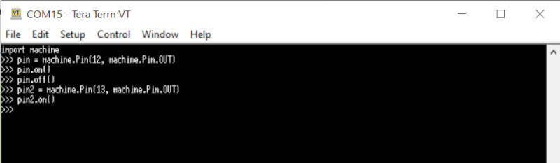
First we try to do some scripting with REPL (Python prompt)
- after installing teraTerm, we can make a connection on the com port through the ftdi-usb dongle. https://osdn.net/projects/ttssh2/downloads/72009/teraterm-4.105.exe/
- once connected we can send python commands to the board. It can do basic python scripts and also control pins inputs and outputs on the board
Now we try to put a python scriptfile on the board. For this we can use the adafruit ampy tool.
https://learn.adafruit.com/micropython-basics-load-files-and-run-code/install-ampy
pip3 install adafruit-ampy
We write a small python code to test this. This code makes the led on pin 13 blink.
import time
from machine import Pin

led = Pin(13, Pin.OUT)

while True:
    led.value(1)
    time.sleep(1)
    led.value(0)
    time.sleep(1)
Uploading the code we do with the PUT command
ampy --port com15 put blinky.py
And to run the code we can use the RUN command
$ ampy --port com15 run blinky.py
When you want the code to automatically run on boot you can use the ampy put command to save the script as a /main.py file on the board.