15. Interface and application programming
This week I worked on commanding the switching of some LEDs on my boards by a web interface.
Assignment:
   individual assignment:
      write an application that interfaces a user with an
         input &/or output device that you made
   group assignment:
      compare as many tool options as possible
Wemos Lolin D1 pro
To be able to make a connection between a web page and my board, I looked for something to make the link and be able to be connected to internet. I found a wemos lolin d1 mini pro which have this specific path that makes wifi antenna. It also have a lot of pins that I could use for serial communication, as I did previous week. That is exactly what I need.

To discover this board, I looked for some documentation on internet. On the wemos website, there is some information about the baord and especially the microcontroller. This Wemos is working with an ESP8266. To use the board, I searched for some tutorial on internet. This tutorial, in french helped me to programm the Wemos Lolin D1 mini pro with a blink.
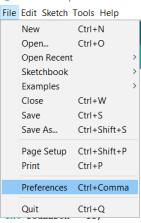
First I installed the board in the Arduino IDE, in Additional board managers I copied this URL:
http://arduino.esp8266.com/stable/package_esp8266com_index.json

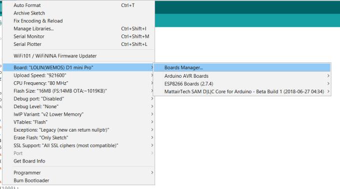
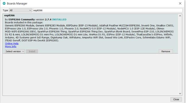
Then in board managers I checked the installation of the esp8266. The installing of the ESP8266 is also written here in english.
And now it is said that I am supposed to see the board connected to a port but it was not the case. Here I got the first problem. My board is not recognized by my computer. After a lot of reseraches on internet, I found that I need to install a driver on my computer, the CH340 driver. I downloaded the file and tried to install this driver but my computer told me that the installation was a failure.
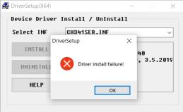
To fix that, I had to do a right click on the .INF file and install, and here it went well.
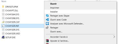
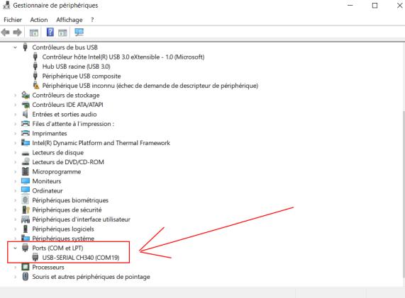
Now my board is recognized by my computer.
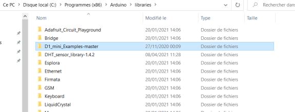
I also downloaded some examples for D1 mini pro on github, download the folder and put it somewhere on the Arduino folder on my computer.

/*
 * Blink
 * Turns on the onboard LED on for one second, then off for one second, repeatedly.
 * This uses delay() to pause between LED toggles.
 */

void setup() {
  pinMode(BUILTIN_LED, OUTPUT);  // initialize onboard LED as output
}

void loop() {
  digitalWrite(BUILTIN_LED, HIGH);  // turn on LED with voltage HIGH
  delay(1000);                      // wait one second
  digitalWrite(BUILTIN_LED, LOW);   // turn off LED with voltage LOW
  delay(1000);                      // wait one second
}
And now I am able to flash the blink code examples on the Wemos.
And the LED is blinking.
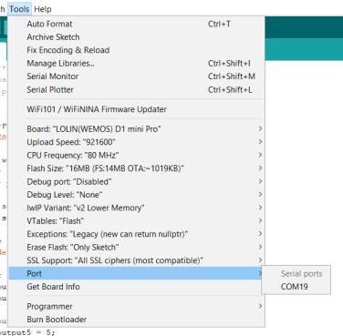
I have to be careful to select the right COM port.
Create a web server
Now that the board is detected by my computer and able to be programmed, I have to figure out how to create a web server with the Wemos. I use this tutorial to discover how to create a web server with my ESP8266. Here is the code I copy paste in the Arduino IDE and I just change the WiFi settings with the one in AgriLab. The purpose of this code is to control to LED plugged to the pin 4 and the pin 5 of the Wemos so I redid the the wiring and it works.
/*********
  Rui Santos
  Complete project details at http://randomnerdtutorials.com
*********/

// Load Wi-Fi library
#include <ESP8266WiFi.h>

// Replace with your network credentials
const char* ssid     = "AgriLabs";
const char* password = "";

// Set web server port number to 80
WiFiServer server(80);

// Variable to store the HTTP request
String header;

// Auxiliar variables to store the current output state
String output5State = "off";
String output4State = "off";

// Assign output variables to GPIO pins
const int output5 = 5;
const int output4 = 4;

// Current time
unsigned long currentTime = millis();
// Previous time
unsigned long previousTime = 0;
// Define timeout time in milliseconds (example: 2000ms = 2s)
const long timeoutTime = 2000;

void setup() {
  Serial.begin(115200);
  // Initialize the output variables as outputs
  pinMode(output5, OUTPUT);
  pinMode(output4, OUTPUT);
  // Set outputs to LOW
  digitalWrite(output5, LOW);
  digitalWrite(output4, LOW);

  // Connect to Wi-Fi network with SSID and password
  Serial.print("Connecting to ");
  Serial.println(ssid);
  WiFi.begin(ssid, password);
  while (WiFi.status() != WL_CONNECTED) {
    delay(500);
    Serial.print(".");
  }
  // Print local IP address and start web server
  Serial.println("");
  Serial.println("WiFi connected.");
  Serial.println("IP address: ");
  Serial.println(WiFi.localIP());
  server.begin();
}

void loop(){
  WiFiClient client = server.available();   // Listen for incoming clients

  if (client) {                             // If a new client connects,
    Serial.println("New Client.");          // print a message out in the serial port
    String currentLine = "";                // make a String to hold incoming data from the client
    currentTime = millis();
    previousTime = currentTime;
    while (client.connected() && currentTime - previousTime <= timeoutTime) { // loop while the client's connected
      currentTime = millis();
      if (client.available()) {             // if there's bytes to read from the client,
        char c = client.read();             // read a byte, then
        Serial.write(c);                    // print it out the serial monitor
        header += c;
        if (c == '\n') {                    // if the byte is a newline character
          // if the current line is blank, you got two newline characters in a row.
          // that's the end of the client HTTP request, so send a response:
          if (currentLine.length() == 0) {
            // HTTP headers always start with a response code (e.g. HTTP/1.1 200 OK)
            // and a content-type so the client knows what's coming, then a blank line:
            client.println("HTTP/1.1 200 OK");
            client.println("Content-type:text/html");
            client.println("Connection: close");
            client.println();

            // turns the GPIOs on and off
            if (header.indexOf("GET /5/on") >= 0) {
              Serial.println("GPIO 5 on");
              output5State = "on";
              digitalWrite(output5, HIGH);
            } else if (header.indexOf("GET /5/off") >= 0) {
              Serial.println("GPIO 5 off");
              output5State = "off";
              digitalWrite(output5, LOW);
            } else if (header.indexOf("GET /4/on") >= 0) {
              Serial.println("GPIO 4 on");
              output4State = "on";
              digitalWrite(output4, HIGH);
            } else if (header.indexOf("GET /4/off") >= 0) {
              Serial.println("GPIO 4 off");
              output4State = "off";
              digitalWrite(output4, LOW);
            }

            // Display the HTML web page
            client.println("<!DOCTYPE html><html>");
            client.println("<head><meta name=\"viewport\" content=\"width=device-width, initial-scale=1\">");
            client.println("<link rel=\"icon\" href=\"data:,\">");
            // CSS to style the on/off buttons
            // Feel free to change the background-color and font-size attributes to fit your preferences
            client.println("<style>html { font-family: Helvetica; display: inline-block; margin: 0px auto; text-align: center;}");
            client.println(".button { background-color: #195B6A; border: none; color: white; padding: 16px 40px;");
            client.println("text-decoration: none; font-size: 30px; margin: 2px; cursor: pointer;}");
            client.println(".button2 {background-color: #77878A;}</style></head>");

            // Web Page Heading
            client.println("<body><h1>ESP8266 Web Server</h1>");

            // Display current state, and ON/OFF buttons for GPIO 5
            client.println("<p>GPIO 5 - State " + output5State + "</p>");
            // If the output5State is off, it displays the ON button
            if (output5State=="off") {
              client.println("<p><a href=\"/5/on\"><button class=\"button\">ON</button></a></p>");
            } else {
              client.println("<p><a href=\"/5/off\"><button class=\"button button2\">OFF</button></a></p>");
            }

            // Display current state, and ON/OFF buttons for GPIO 4
            client.println("<p>GPIO 4 - State " + output4State + "</p>");
            // If the output4State is off, it displays the ON button
            if (output4State=="off") {
              client.println("<p><a href=\"/4/on\"><button class=\"button\">ON</button></a></p>");
            } else {
              client.println("<p><a href=\"/4/off\"><button class=\"button button2\">OFF</button></a></p>");
            }
            client.println("</body></html>");

            // The HTTP response ends with another blank line
            client.println();
            // Break out of the while loop
            break;
          } else { // if you got a newline, then clear currentLine
            currentLine = "";
          }
        } else if (c != '\r') {  // if you got anything else but a carriage return character,
          currentLine += c;      // add it to the end of the currentLine
        }
      }
    }
    // Clear the header variable
    header = "";
    // Close the connection
    client.stop();
    Serial.println("Client disconnected.");
    Serial.println("");
  }
}
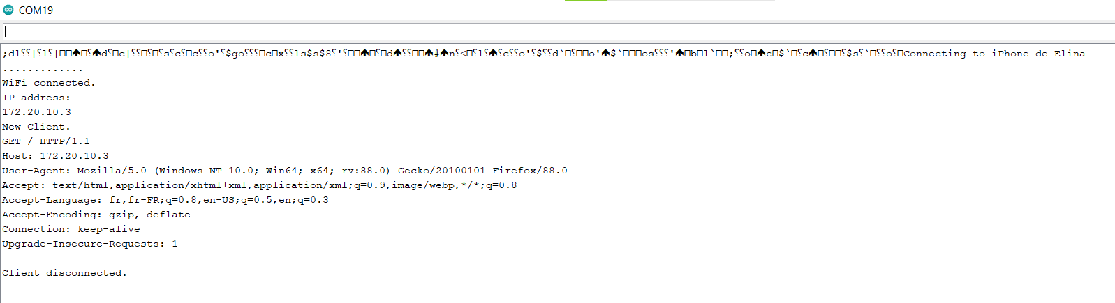
Here is what it is print on the serial monitor, with the IP adress that I copy paste in my browser.
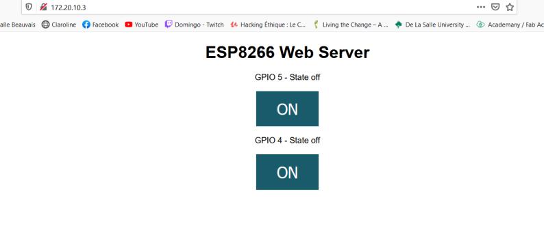
And here it is what the browser is shown on my browser, with the two buttons that control the LEDs.
And the video where I can control the 2 LEDs.
The 2 LEDs are blinking according to the button on the webpage. Now I understood how to create a web server with the Wemos Lolin, I have to make a Serial communication between one of my secondary board from the previous week and the Wemos.
Serial communication between Wemos Lolin D1 mini pro and SAMD11C
I took the code I wrote last week, but this time, because the microcontroller of the Wemos is a ESP8266, I cannot use the second serial of the microcontroller, but I have to set one with SoftwareSerial.h library. It is working as the same way as the serial communication between two SAMD11C, a value is written on the Serial monitor and after sent in mySerial.
#include <SoftwareSerial.h>
#define TXPIN 5 //tx
#define RXPIN 4 //rx

SoftwareSerial mySerial(RXPIN, TXPIN);

void setup() {
  pinMode(BUILTIN_LED, OUTPUT);  // initialize onboard LED as output
  Serial.begin(115200);
  mySerial.begin(115200);
}

void loop() {
  digitalWrite(BUILTIN_LED, HIGH);  // turn on LED with voltage HIGH
  delay(1000);                      // wait one second
  digitalWrite(BUILTIN_LED, LOW);   // turn off LED with voltage LOW
  delay(1000);                      // wait one second
  if (Serial.available()){
    int prout = Serial.read();
    Serial.write("prout : ");
    Serial.write(prout);
    mySerial.write(prout); //send accross the serial the value that is written on the serial USB
  }

}
Here is the code I flashed into my SAMD11C, it receive the value from mySerial in Serial2, because it is the pins plugged for the serial communication and respond according to the value received.
 /**
 * code secondary
 */

int boardID = 3; //change the number depending on the board
int blueLEDoff = 30;
int greenLEDoff = 20;
int redLEDoff = 10;

int blueLEDon = 31;
int greenLEDon = 21;
int redLEDon = 11;

void setup(){
  Serial2.begin(115200);
  pinMode(2, OUTPUT); //red
  pinMode(14, OUTPUT); //greeb
  pinMode(15, OUTPUT); //blue
      digitalWrite(14, HIGH);
      delay(1000);
      digitalWrite(14, LOW);

      digitalWrite(2, HIGH);
      delay(1000);
      digitalWrite(2, LOW);

      digitalWrite(15, HIGH);
      delay(1000);
      digitalWrite(15, LOW);
}

void loop(){
  int i = 0;
  if(Serial2.available()){
    i = Serial2.parseInt();
  }
  if(i != 0){
    if (i == greenLEDon){
      digitalWrite(14, HIGH);
    }
    else if (i == greenLEDoff){
      digitalWrite(14, LOW);
    }
    else if (i == redLEDon){
      digitalWrite(2, HIGH);
    }
    else if (i == redLEDoff){
      digitalWrite(2, LOW);
    }
    else if (i == blueLEDon){
      digitalWrite(15, HIGH);
    }
    else if (i == blueLEDoff){
      digitalWrite(15, LOW);
    }
  }
}
On this website I found some tips with ESP8266. I understood that the TX and RX pins are actually taken by the USB serial and I have to set ohters pins to be able to have a serial communication with two microcontrollers.
My instructor Florent worked with the ESP8266 last year and I found here some help to understand the code I have to write to have communication.
Now that I am able to make a serial communication between a secondary board and the Wemos who is acting like the master I just have to mix the two codes for the Wemos to create a web server that interact with the secondary board with LED.
Interfaces
So I mixed the two codes from the Serial communication and the web interface in adding the softwareserial.h library and settings the pins for communication.
I also added a button to be able to add a switch for a LED. The URL of the page is changing according to the button state. So thanks to the URL, I set some values sent accross the serial to be able to communicate between 2 boards (and more). We will see again those values in the code flashed in the secondary board.
Here is the code for the master:
// Load Wi-Fi library
#include <ESP8266WiFi.h>
#include <SoftwareSerial.h>
#define TXPIN 5 //tx
#define RXPIN 4 //rx

SoftwareSerial mySerial(RXPIN, TXPIN);

// Replace with your network credentials
const char* ssid     = "AgriLabs";
const char* password = "";

// Set web server port number to 80
WiFiServer server(80);

// Variable to store the HTTP request
String header;

// Auxiliar variables to store the current output state
String outputgreenState = "off";
String outputredState = "off";
String outputblueState = "off";

// Assign output variables to GPIO pins
//const int output5 = D1;

int boardID = 0;

void setup() {
  //Serial.begin(115200);
  // Initialize the output variables as outputs
  //pinMode(output5, OUTPUT);
  pinMode(BUILTIN_LED, OUTPUT);  // initialize onboard LED as output
  Serial.begin(115200);
  mySerial.begin(115200);

  // Set outputs to LOW
  // digitalWrite(output5, LOW);


  // Connect to Wi-Fi network with SSID and password
  Serial.print("Connecting to ");
  Serial.println(ssid);


  WiFi.begin(ssid, password);
  while (WiFi.status() != WL_CONNECTED) {
    delay(500);
    Serial.print(".");
  }
  // Print local IP address and start web server
  Serial.println("");
  Serial.println("WiFi connected.");
  Serial.println("IP address: ");
  Serial.println(WiFi.localIP());
  server.begin();
}

void loop(){
  WiFiClient client = server.available();   // Listen for incoming clients

  if (client) {                             // If a new client connects,
    Serial.println("New Client.");          // print a message out in the serial port
    String currentLine = "";                // make a String to hold incoming data from the client
    while (client.connected()) {            // loop while the client's connected
      if (client.available()) {             // if there's bytes to read from the client,
        char c = client.read();             // read a byte, then
        Serial.write(c);                    // print it out the serial monitor
        header += c;
        if (c == '\n') {                    // if the byte is a newline character
          // if the current line is blank, you got two newline characters in a row.
          // that's the end of the client HTTP request, so send a response:
          if (currentLine.length() == 0) {
            // HTTP headers always start with a response code (e.g. HTTP/1.1 200 OK)
            // and a content-type so the client knows what's coming, then a blank line:
            client.println("HTTP/1.1 200 OK");
            client.println("Content-type:text/html");
            client.println("Connection: close");
            client.println();

            // turns the GPIOs on and off
            if (header.indexOf("GET /green/on") >= 0) {
              Serial.println("GPIO 5 on");
              outputgreenState = "on";
              boardID = 21;
              mySerial.print(boardID);
              //digitalWrite(output5, HIGH);
            } else if (header.indexOf("GET /green/off") >= 0) {
              Serial.println("GPIO 5 off");
              outputgreenState = "off";
              boardID = 20;
              mySerial.print(boardID);
            } else if (header.indexOf("GET /red/on") >= 0) {
              Serial.println("GPIO 5 off");
              outputredState = "on";
              boardID = 11;
              mySerial.print(boardID);
            } else if (header.indexOf("GET /red/off") >= 0) {
              Serial.println("GPIO 5 off");
              outputredState = "off";
              boardID = 10;
              mySerial.print(boardID);
            } else if (header.indexOf("GET /blue/on") >= 0) {
              Serial.println("GPIO 5 off");
              outputblueState = "on";
              boardID = 31;
              mySerial.print(boardID);
            } else if (header.indexOf("GET /blue/off") >= 0) {
              Serial.println("GPIO 5 off");
              outputblueState = "off";
              boardID = 30;
              mySerial.print(boardID);
            }


            // Display the HTML web page
            client.println("<!DOCTYPE html><html>");
            client.println("<head><meta name=\"viewport\" content=\"width=device-width, initial-scale=1\">");
            client.println("<link rel=\"icon\" href=\"data:,\">");
            // CSS to style the on/off buttons
            // Feel free to change the background-color and font-size attributes to fit your preferences
            client.println("<style>html { font-family: Helvetica; display: inline-block; margin: 0px auto; text-align: center;}");
            client.println(".button { background-color: #195B6A; border: none; color: white; padding: 16px 40px;");
            client.println("text-decoration: none; font-size: 30px; margin: 2px; cursor: pointer;}");
            client.println(".button2 {background-color: #77878A;}</style></head>");

            // Web Page Heading
            client.println("<body><h1>LED SAMD11C</h1>");

            // Display current state, and ON/OFF buttons for GPIO 5
            client.println("<p>green LED " + outputgreenState + "</p>");
            // If the output5State is off, it displays the ON button
            if (outputgreenState=="off") {
              client.println("<p><a href=\"/green/on\"><button class=\"button\">Allumage</button></a></p>");
            } else {
              client.println("<p><a href=\"/green/off\"><button class=\"button button2\">Eteignage</button></a></p>");
            }

            client.println("<p>red LED " + outputredState + "</p>");
            // If the output5State is off, it displays the ON button
            if (outputredState=="off") {
              client.println("<p><a href=\"/red/on\"><button class=\"button\">Allumage</button></a></p>");
            } else {
              client.println("<p><a href=\"/red/off\"><button class=\"button button2\">Eteignage</button></a></p>");
            }

            client.println("<p>blue LED " + outputblueState + "</p>");
            // If the output5State is off, it displays the ON button
            if (outputblueState=="off") {
              client.println("<p><a href=\"/blue/on\"><button class=\"button\">Allumage</button></a></p>");
            } else {
              client.println("<p><a href=\"/blue/off\"><button class=\"button button2\">Eteignage</button></a></p>");
            }


            client.println("</body></html>");

            // The HTTP response ends with another blank line
            client.println();
            // Break out of the while loop
            break;
          } else { // if you got a newline, then clear currentLine
            currentLine = "";
          }
        } else if (c != '\r') {  // if you got anything else but a carriage return character,
          currentLine += c;      // add it to the end of the currentLine
        }
      }
    }
    // Clear the header variable
    header = "";
    // Close the connection
    client.stop();
    Serial.println("Client disconnected.");
    Serial.println("");
  }
}
Here is the code for the secondary. The state of the LED is changing according to the value send to the Serial by the Wemos and the webpage (with the URL as we can see before).
/**
 * code secondary
 */

int boardID = 3; //change the number depending on the board
int blueLEDoff = 30;
int greenLEDoff = 20;
int redLEDoff = 10;

int blueLEDon = 31;
int greenLEDon = 21;
int redLEDon = 11;

void setup(){
  Serial2.begin(115200);
  pinMode(2, OUTPUT); //red
  pinMode(14, OUTPUT); //greeb
  pinMode(15, OUTPUT); //blue
      digitalWrite(14, HIGH);
      delay(1000);
      digitalWrite(14, LOW);

      digitalWrite(2, HIGH);
      delay(1000);
      digitalWrite(2, LOW);

      digitalWrite(15, HIGH);
      delay(1000);
      digitalWrite(15, LOW);
}

void loop(){
  int i = 0;
  if(Serial2.available()){
    i = Serial2.parseInt();
  }
  if(i != 0){
    if (i == greenLEDon){
      digitalWrite(14, HIGH);
    }
    else if (i == greenLEDoff){
      digitalWrite(14, LOW);
    }
    else if (i == redLEDon){
      digitalWrite(2, HIGH);
    }
    else if (i == redLEDoff){
      digitalWrite(2, LOW);
    }
    else if (i == blueLEDon){
      digitalWrite(15, HIGH);
    }
    else if (i == blueLEDoff){
      digitalWrite(15, LOW);
    }
  }
}
And here is the result.
At the end, I connected two secondaries boards SAMD11C controlled by the master baord, the Wemos Lolin D1 mini pro. I flashed the same secondary code in the two boards SAMD11C.
Because it is serial communcation, I can add as many secondary boards as I want and make their LEDs switch on off together. One thing I would have liked to do is to have the choice of the board we would like to work with, with a board ID, with for examples a form to choose the board ID.
Group assignement
From the group page
This week we have seen the programming of a user interface. For this we used different methods to create our interfaces. Elina and Theo used a web page in HTML to communicate with their board and Antonio made a programmable in Python language. In this page you will discover the advantages and disadvantages of these two methods.
Interest/disinterest of the methods
In the past Computers used to have simple text based interfaces.

Over the years this changed to have visual more interactive interfaces.

Language comparison:
| HTML method | Python programming | |
|---|---|---|
| Positive | Wireless connection. Can control a mechanism even from a distance. Works on computer, tablet or smartphone. Lots of documentation | Multiplatform and with Python integration to multiple programming paradigms |
| Negative | Need a wifi network to work. Loss connection regularly. Speed of action can sometimes be long. | Python is a interpreted language that doesn’t compiles itself except by using Nuitka or other code translators |
Useful links
- My previous week for serial communication
- Wemos website for Lolin D1 mini pro
- This tutorial to discover Wemos Lolin D1 mini in french
- Install ESP8266 in Arduino in english
- The CH340 driver
- Some examples for D1 mini pro
- This tutorial to discover how to create a web server with my ESP8266
- This website with some tips with ESP8266
- Florent’s work with the ESP8266 last year