14. Networking and communications
This week I worked on discovering networking and communication process.
Assignment:
   individual assignment:
      design, build, and connect wired or wireless node(s)
      with network or bus addresses
   group assignment:
      send a message between two projects
On the screen, writting 1, 2 and 3 on the serial monitor.
if the video does not work, please open it in an other brower, like google Chrome
And the result on the boards according to their ID.
The idea
First of all, I had to understand what was the goal of this week. After some researches I decided to focus on wired communication and do a bus with LED, that blink according to the ID of the board, the address that I will set.
I was inspired by the bus Neil made with ATtiny45
This image comes from the website from fabacademy, week networking and communications
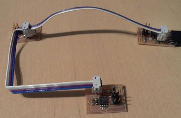
and the bus made by Adrian Torres made with the ATtiny412
This image comes from Adrian Torres’ website, week networking and communications
but I wanted to use the microcontroller SAMD11C14A I already used during previous weeks.
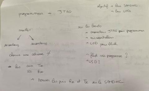
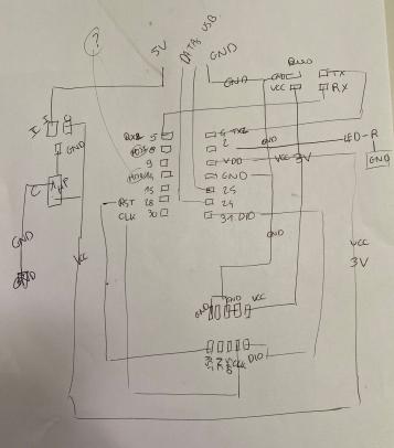
How to understand the assignement of the week was not the easy part. I put on a paper what I understood and what was the goal of the week, with what I know and what I need to do, according to what has been done by Adrian Torres with the ATtiny. My programmer is in JTAG. So to flash my boards on the bus, I need a JTAG connector. I also need an USB key to send the code to the board. I add the microcontroller, and some LEDs to blink. And finally the last components, a connector for Tx and Rx, GND and VCC. I used this communication, the Serial communication, or the other name, UART communication because I already seen those words to the diagramm of the pinout on the SAMD11C.
From the mattairtech git, the documentation about the pin with the microcontroller.
====================================== ATsamD11C14A =====================================
Other  COM   PWM  Analog  INT  Arduino*           Arduino*  INT  Analog  PWM   COM  Other
=========================================================================================
                                  1-------------------
  SCK*/RX2  TCC01    *     *    5 | A5             A4 | 4    *    *  TCC00 MOSI*/TX2  REF
    MOSI*   TCC02          *    8 | A8 (XIN)       A2 | 2    *    *                   DAC
    SCK*    TCC03          *    9 | A9 (XOUT)     Vdd |
  SDA/MISO*  TC10    *    NMI  14 | A14           Gnd |
   SCL/SS*   TC11    *     *   15 | A15           A25 | 25                    USB/DP
BOOT                           28 | A28/RST       A24 | 24                    USB/DM
SWDCLK  TX1/MISO*              30 | A30           A31 | 31   *            RX1/SS*   SWDIO
                                   -------------------

* Most pins can be used for more than one function. When using PIN_MAP_STANDARD, the port
  pin number printed on the chip above is also used in Arduino (but without the 'A') for
  all of the supported functions (ie: digitalRead(), analogRead(), analogWrite(), etc.).
  When using PIN_MAP_COMPACT, the Arduino numbering is sequential starting from 0 at the
  top left pin (A5). PIN_MAP_COMPACT uses less FLASH.
* When USB CDC is enabled, Serial refers to SerialUSB, otherwise it refers to Serial1.
* When using ONE_UART_NO_WIRE_ONE_SPI, use SPI on pins 4, 5, 14, and 15.
  When using NO_UART_ONE_WIRE_ONE_SPI, use SPI on pins 8, 9, 30, and 31.
* Tone available on TC2. TC2 is not routed to pins in the D11C14A.
* Leave pin A30 floating (or use external pullup) during reset.
* DO NOT connect voltages higher than 3.3V!
So I connected to a 4 pins connector RX2 and TX2, the GND and the power for the microcontroller.
I draw roughly my board on a paper and I went to see Luc my instrutor to check if I was right about that.
Drawing on KiCad, milling and soldering
With KiCad, a software I already used during previous week, as the electronics design week. I drew the schematic, with 3 LEDs and their resistors, the microcontroller, the JTAG connector to be able to flash the board with my programmer, an USB connector to be able to connect the boards to my computer, a regulator that transform a 5V into a 3.3V with a capacitor, and a 4 pins connector with one connected to the GND, one connected to the 3.3V, one connected to an Rx pin of the microcontroller, and the last one to the Tx pin.
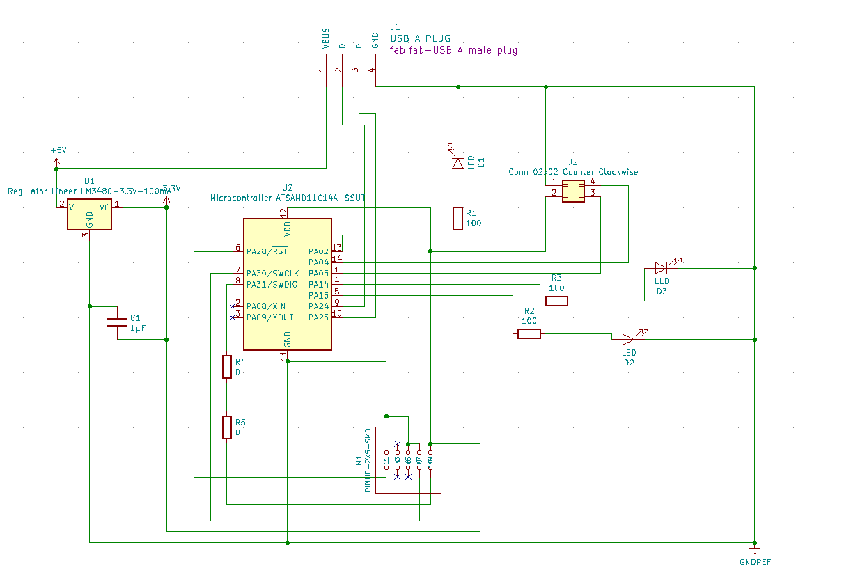
Then I drew the trace on the PCB. Because there is few components the drawing of the traces went pretty well.
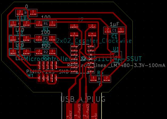
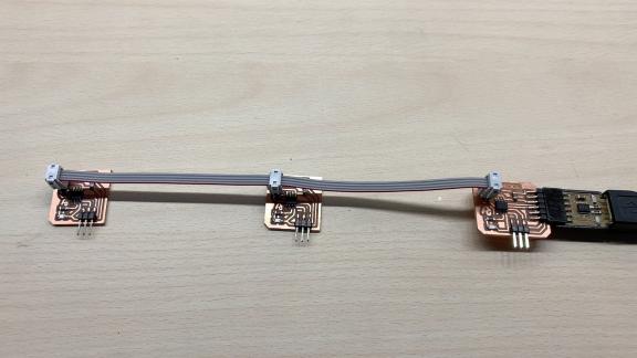
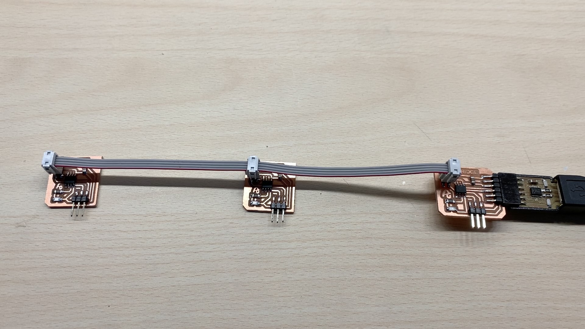
Then I milled 3 boards like this, to do be able to do a communication, and this way I will be able to show that I can add more boards to do a bigger network.
I created a cable. For this cable I wired all the ground, and all the current pins together. For the tx and rx pins, I linked them like this: Rx pins are linked for both secondary boards, but for the master, I inverted the wire. The tx pin from the master has to be linked to the rx pins of the secondaries, and same for the rx pin of the master that has to be linked to the tx pins of all the secondarues.
To the cable I first add some mouthpiece at the end of the wire.
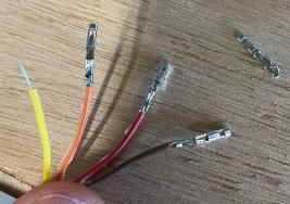
To do that, with the plier I block the mouthpiece.

Then I inserted the bare wire.
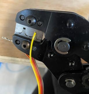
Insert all the wire in the connector in being careful of the direction of insertion.
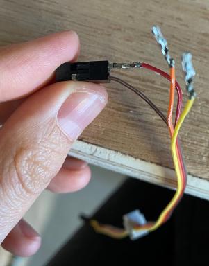
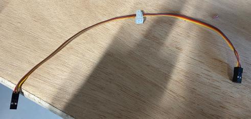
And here is the cable.
Flashing the boards
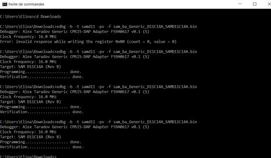
I flashed all the boards with edbg but here I discovered a problem. When I plugged all the boards with the cable, and one to the computer, the regulator of the board plugged to the computer is warming a lot. Howerver I flashed the boards with the regulator warming a lot.
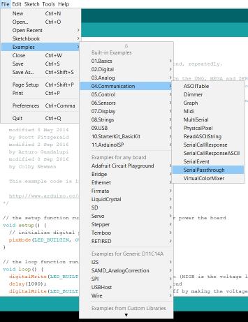
I flashed this blink code to all the boards to see if they are able to receive a code.
// the setup function runs once when you press reset or power the board
void setup() {
  // initialize digital pin LED_BUILTIN as an output.
  pinMode(2, OUTPUT);
  pinMode(14, OUTPUT);
  pinMode(15, OUTPUT);
}

// the loop function runs over and over again forever
void loop() {
  digitalWrite(2, HIGH);   // turn the LED on (HIGH is the voltage level)
  digitalWrite(14, HIGH);
  digitalWrite(15, HIGH);
  delay(1000);                       // wait for a second
  digitalWrite(2, LOW);    // turn the LED off by making the voltage LOW
  digitalWrite(14, LOW)
  digitalWrite(15, LOW)
  delay(1000);                       // wait for a second
}
Each board are blinking when I plug it separately to my computer, but when I plug the cable, the regulator warms a lot and there is not enough current to make all the LEDs blink on all the boards as we can see on the video.
There is really a problem, it should not warm like this, so I tried to discover what is going on. I supply with some wire a 5V current between 2 boards, with one plug to the computer, and here the LEDs are blinking well, without warm on the regulator.
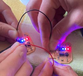
So I understood that only one regulator is supplying 3 boards, that is why it is warming a lot. So I cut the trace of current on the 4 pins connector, and link it with a wire to directly the 5V. That way, each board receive 5V that goes in each regulator and each regulator supply its own microcontroller. Problem is solved. All the boards can blink properly with its own code. Now I have to think to a way to make them communicate accross the cable with an adress.
Communication of the boards (master/secondary)
To understand the serial communication to make my LEDs bus I wrote on a paper what I understood.
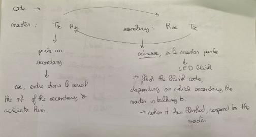
The Tx of the master has to talk to the Rx of the secondary, with each secondary have an adress.
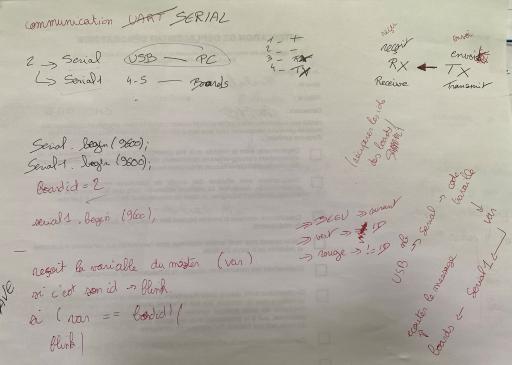
I have to use two differents Serial, one serial is the USB, the second one is the communication Serial by the RX/TX pins. The goal is that the master receive a value on the serial monitor, by USB, send this value on the Serial RX/TX and for the secondary, if the value, the variable, is the same as its ID, so the secondary is doing something, here it switchs on the green LED if it is itself, if it is not, it switch on the red LED. The blue LED is just a checking if there is current flowing inisde the microcontroller.

To understand how to communicate between 2 boards, I receive the help of my instructor Florent.
I first checked the code that Adrian has made for his Attiny412 bus but it didn’t work. He used
But this code is working with Serial and Serial1. We tried to flash this code to two boards but we could not make them communicate together between 2 serial monitors for 2 different computers.
Thanks to the documentation Quentin from the ULB has made for the SAMD11C communication UART, we discover that there is different kind of serial. Serial is the SerialUSB, that I already use. Serial1 and Serial2 are two Serials using to communicate in UART, or named also as Serial communication.
Because the communication needs 2 serials, I need to be careful during flash the code to have 2 UART on the configuration of the flashing.
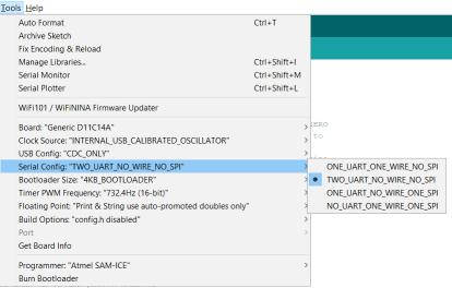
Here is the code we finally flashed to 2 boards to be able to communicate between 2 computers, with serial communication.
void setup() {
   Serial.begin(0);
   Serial2.begin(115200, SERIAL_8E2);
}

void loop() {
   if (Serial.available()) {
      Serial2.write((char) Serial.read());
   }
   if (Serial2.available()) {
      Serial.write((char) Serial2.read());
   }
}
SERIAL_8E2 is the configuration of the communication, the data size is 8 bits, with the parity Even, and stop bits is 2 bits. The default config is SERIAL_8N1.
This line is the configuration, it was needed for a microcontroller Attiny but not for the SAMD11C.
Group assignment
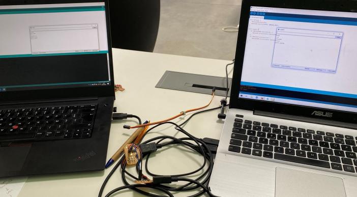
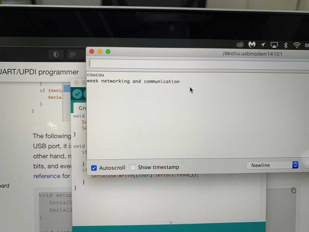
This week the group assignment was to send a message between two projects. For this we used Elina’s board and Theo’s board. For the communication voice we decided to use the Tx/Rx voice. We were then able to send messages between the two boards. In the rest of this documentation we will show you how to send a message between two SAMD11Cs using Tx/Rx voice.
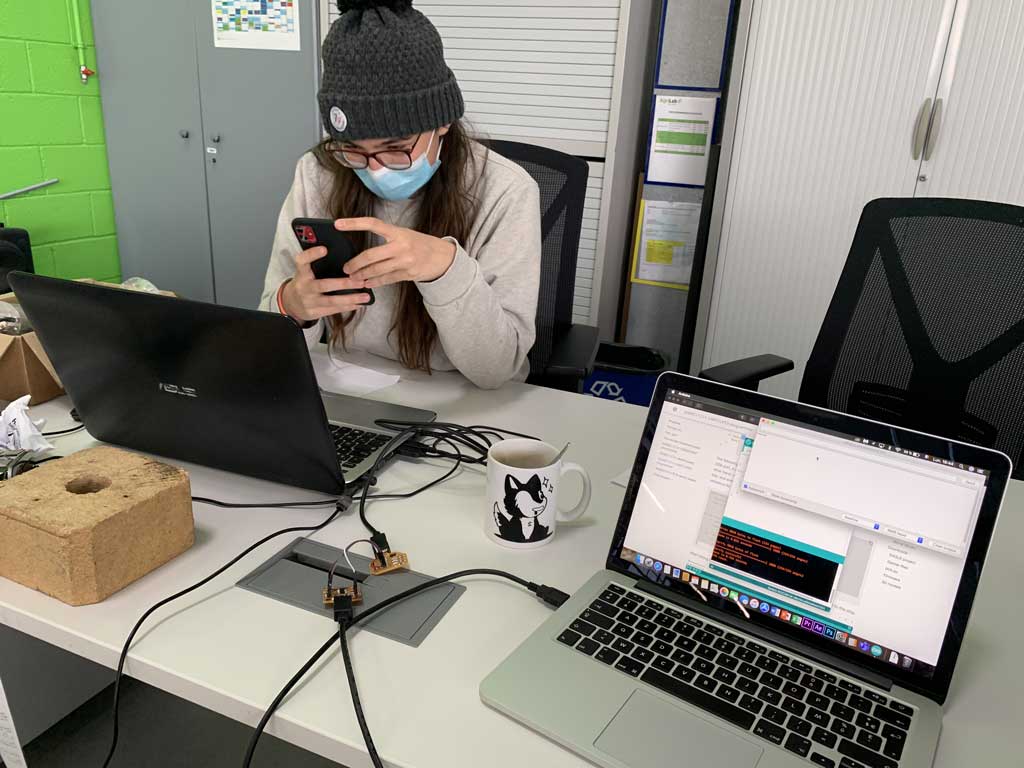
Elina took a picture in a same time with her phone
Here is the picture from the other screen.
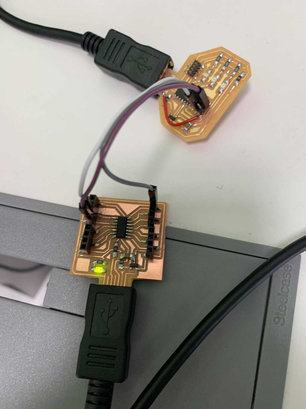
Wiring
Concerning the connection, it is quite simple. It is enough to connect the Tx terminal of the SAMD11C of Elina to the Rx pin of the board of Theo. Inversely for the Rx terminal. Also connect the GNDs together so that the electrons can flow. Then you just need to power the two boards. For that we used the USB port present on our computers and on our boards.
The code
For the code part we used Quentin‘s code on his page. Here is the code
void setup() {
   SerialUSB.begin(0);
   Serial1.begin(115200, SERIAL_8E2);
}

void loop() {
   if (SerialUSB.available()) {
      Serial1.write((char) SerialUSB.read());
   }
   if (Serial1.available()) {
      SerialUSB.write((char) Serial1.read());
   }
}
Communication
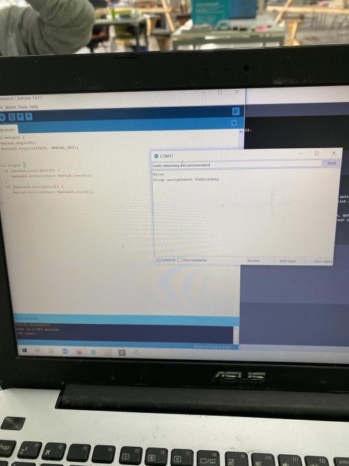
Once we have downloaded the code on our respective boards we could send messages. To do so, you just have to open the serial monitor on the Arduino application and write the message you want to send. Here is the message that Elina sent to Theo.
This group assingment helped us to discover the difference between Serial1 and Serial2. The board of Theo was plugged on RX1 and TX1, the pins 30 and 31 from the SAMD11C, the board of Elina was plugged on the pins RX2 and TX2, which are the pins 4 and 5. In that way we saw that to make the communciation between our 2 boards, Elina needed to use Serial2, and Theo Serial1.
Here is the code flashed on Elina’s board.
void setup() {
   SerialUSB.begin(0);
   Serial2.begin(115200, SERIAL_8E2);
}

void loop() {
   if (SerialUSB.available()) {
      Serial2.write((char) SerialUSB.read());
   }
   if (Serial2.available()) {
      SerialUSB.write((char) Serial2.read());
   }
}
Code
After understanding that there is different kind of serial, I was able to flash the right in the master board and in the secondaries boards.
Here is the codes I wrote and flashed in the boards
The code in the master send accross the serial2 the value that is written on the serial USB.
/**
 * code master
 */

void setup(){
  SerialUSB.begin(9600); //start the communication in USB
  Serial2.begin(9600); //start the communication of the pins RX2/TX2
  pinMode(15, OUTPUT); // blue LED as an output
}

void loop(){
  digitalWrite(15, HIGH); //on the blue LED to check the current
  if (SerialUSB.available()){
    Serial2.write((int) SerialUSB.read()); //send accross the serial2 the value that is written on the serial USB
  }
}
The code on the secondaries is the same for both boards, it is only the boardID that changes. If the value of the serial2 is the same as the board ID, it on off the green LED, if it is not but a value is received, it on off the red LED.
/**
 * code secondary
 */

int boardID = 3; //change the number depending on the board

void setup(){
  Serial2.begin(9600);
  pinMode(2, OUTPUT); //red LED
  pinMode(14, OUTPUT); //green LED
  pinMode(15, OUTPUT); // blue LED
}

void loop(){
  int i = 0;
  digitalWrite(15, HIGH); // on the blue LED to check the current flowing
  if(Serial2.available()){
    i = Serial2.parseInt(); //send the value read on the Serial 2 to a variable to be able to play with it
  }
  if(i != 0){
    if (i == boardID){ // if the value of the serial2 is the same as the board ID, it on off the green LED
      digitalWrite(14, HIGH);
      delay(1000);
      digitalWrite(14, LOW);
    }
    else{ // if it is not but a value is received, it on off the red LED
      digitalWrite(2, HIGH);
      delay(1000);
      digitalWrite(2, LOW);
    }
  }
}
On the screen, writting 1, 2 and 3 on the serial monitor.
if the video does not work, please open it in an other brower, like google Chrome
And the result on the boards according to their ID.