First idea of final Project
This week I worked on defining my final project idea and started to getting used to the documentation process.
My project idea
I want to create an skeleton for a teddy bear. I would like this toy to walk and can move is head that can be remote control.
So here is the teddy bear I would like to start with :


And here is the kind of skeleton I want to put inside
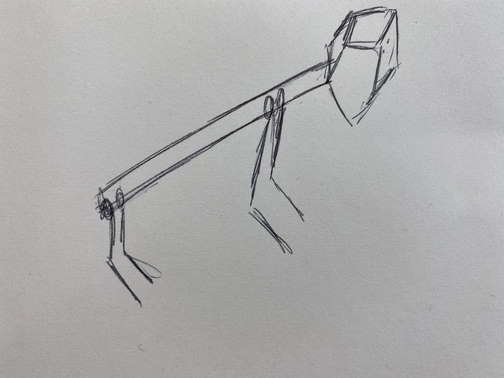
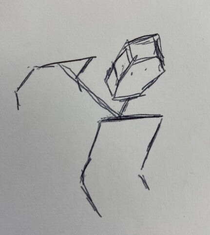
The goal is that he can move around controlled by a remote and move his head left to right or top to bottom.
Research
First I have watch a video from a robot made by Boston Dynamics. This robots is full of inovations and very helpful for humans. I would like to build a robot inside the teddy bear than can walk like it.
The next video is about people who created a Teddy Bear robot, but it is not moving in the room, it only stay and move its arms and head. It inspire me to create a moving head, but I wish my teddy bear robot can move around.
3D Design
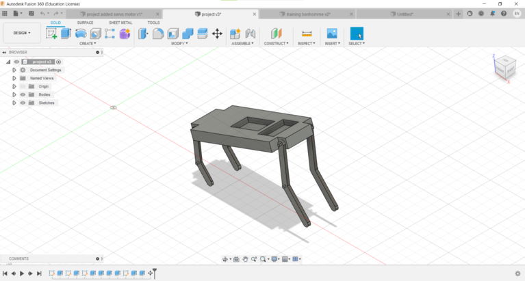
Now I was able to draw the kind of skeleton I want, so I have sketched the support, and then add the legs on it and extrude everything, and put compartment for the batteries and the eletronic board. For my final project I want the legs walking with servo motors, so I searched servo motors shapes on the gallery of autodesk but I was not able to put them inside my skeleton’s shape. So I have drawn an other shape with parametric values and constraints to be able to use it properly.
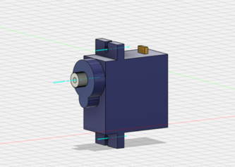
Here is the kind of motor I would like to use :
2D Design
For my final project, my first idea is to laser cut the legs of my robot. So I drew a leg with inkscape.
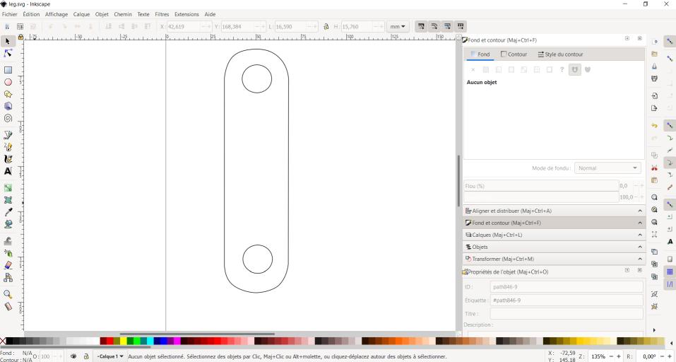
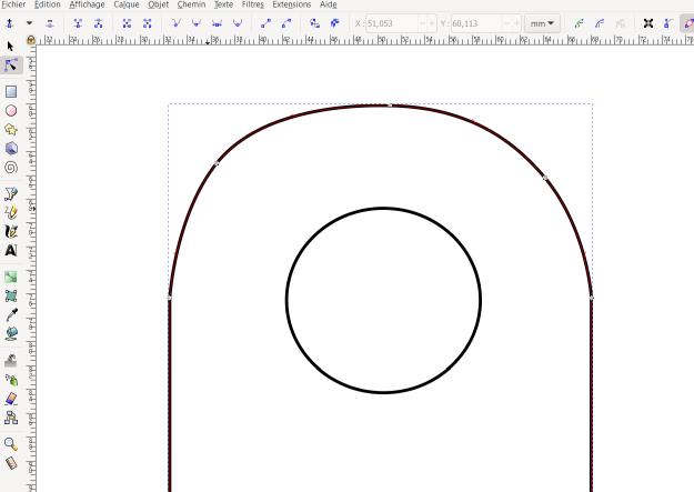
The drawing has to be a vectorial drawing, in order to avoid pixels and to be used by a laser cutter. I drew bezier cuves and straight lines and then adjust the points (nodes) to do a smooth shapes, I didn’t have time to explore all the tools of inkscape to have parametrics shapes but booleans operations allow me to have a more precise shape.
You can see here my computer aided design week and how I used CAD software.
Laser cutter
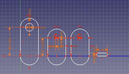
To do the legs of my teddy bear, I want to use the laser cutter. The legs has to do movements. To the movement like an animal walking I need to do kind of joint between two parts of the leg. To to it, I will use ball bearing, that’s why I draw some 2D shapes to do the leg and a place to put the ball bearing. I used FreeCad. I drew the shapes and add some constraints. I wanted to have my file parametric so I can change the size of the ball bearing. To use the ball bearing, there need to be a fix shape, and a shape that will move.
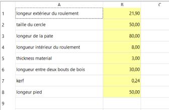
To download the file, click right and select save the file. Here is the file of the leg
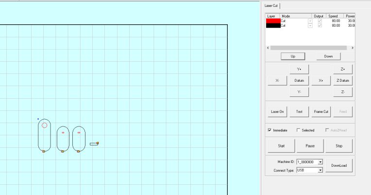
Then I cut my shape with cardboard to do some test with a ball bearing, to understand how it works, and find a visual way to add my servo motors. I used these following parameters : speed 80 and power 30. You can see here my computer controlled cutting week and how I used the laser cutter first.
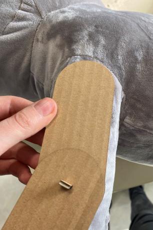
So here is the assembly of my cardboards shapes.
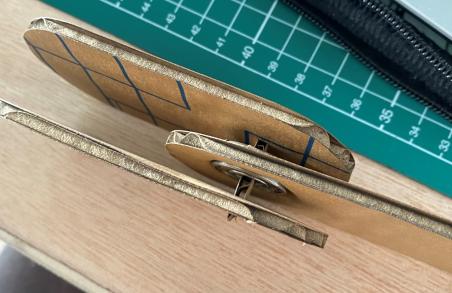
I put my ball bearing in the middle cardboard, and put an axe in the middle of the ball bearing, it is the fixed part.
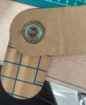
When I set my files I took a too small value for the size of the ball bearing so I did notches with a cutter in the cardboard. I will change this parameter later with a bigger value.
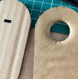
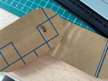
And when I put the assembly next to the leg of my teddy bear it fits pretty well. I will make the leg a litlle bit longer for the front paw but it fits for the back paw.