13. Output devices
This week I worked on milling a board.
Assignment:
   individual assignment:
      add an output device to a microcontroller board you've designed,
         and program it to do something
   group assignment:
      measure the power consumption of an output device
For this week, I designed a new board, to be able to have an output powered with a 5V power source. For my final project, I need a peristaltic pump, working with a DC motor, that’s why I focused this week on motors.


Motors and power
First we got a workshop to discover the motors and the power. A motor needs a lot of power to work, many volts and many ampers. A microcontroller as the SAMD11C I already used can not handle that. We have to figure out how to power a motor without burning the microcontroller. I will use a transistor. For what I understood, a transistor works like allowing electrons to flow or not. We need a power source, for example 12V or 6V to power a motor, plug the motor to it and in between the transistor. One pin of the microcontroller is plugged to the transistor and work as the switch and make the passage for the electrons.
![]()
This image comes from the agrilab wiki about motors and power
On one side of the transistor there is lack of electrons and on the other side there is an excess of electrons. The electrons flowing from one side to the other to produce current and let the electrons flow. When the pin that control the transistor is HIGH, it allows the current to flow, and power the motor. When it is LOW, there is no electrons flowing
A DC motor works with magnets and coils. When there is power, the two sides repulse each other that make the motor turn.

This image comes from the agrilab wiki about motors and power
When we stop the current, the motor still continue to turn a litle bit and keep making a magnetic field. To avoid that magnetic field with electrons to come back to the microcontroller, we need to make a loophole to maintain the electrons. That’s why we plugged a capacitor and a diode after the motor.
Test of the motor from a printer
For the group assignment I tested a DC motor. In my lab we have some printer that are not working anymore, and I took from it a DC motor. I tested the motor with a DC motor supply, and by hearing the noise of the motor and the speed of it, I assumed that the motor is working at 3V to 6V, and needs around 0.120A at 5V.
Here is the motor plugged to the DC power supply.

And here it is the value shown on the DC power supply, with how many ampers it consumes at 5V.

Here is the motor powered with 5V.
I tested also with a low woltage, at 1V, and it works also but the motor spins slower.
6V motor and H bridge with Arduino
To test a motor, I used a H-bridge and an arduino Board with the code I wrote during the machine week with the peristaltic pump
I did the same wiring.

And because this motor is a 6V motor, I powered the H-bridge with 6V.

As a reminder, here is my code, using platform.io with VSCode:
#include <Arduino.h>

//declaration des variables et des constantes
int enA = 9; //les pins avec des tilds
int in1 = 10;
int in2 = 11;

int speedmotor = 0; //vitesse du moteur

void setup() {
  // put your setup code here, to run once:
  pinMode(enA, OUTPUT);
  pinMode(in1, OUTPUT);
  pinMode(in2, OUTPUT);
  Serial.begin(9600); //la valeur de communication
}

void move(int speed, bool testforward) {// speed between 0 and 255 analog write, test d'un booléen pour aller dans un sens ou dans un autre
  if (testforward){
    digitalWrite(in1, HIGH); //envoie du courant dans un sens (set to +)
    digitalWrite(in2, LOW); //en envoie pas, le récupère (set to -)
  }
  else{
    digitalWrite(in1, LOW);
    digitalWrite(in2, HIGH);
  }
  analogWrite(enA, speed);
}

void loop() {
  // put your main code here, to run repeatedly:
  if(Serial.available() > 0){ //si la board arduino est branchée
    speedmotor = Serial.parseInt(); // speedmotor recupere la valeur inscrite dans le serial
    Serial.println(speedmotor);
    if (speedmotor == 0){
      return;
    }
    if(speedmotor > 0){ //si speedmoto a une valeur, plus grande que 0
      if (speedmotor > 255){
        speedmotor = 255; //speedmotor est forcé à 255 maxi
      }
      move(speedmotor, true); //alors marche avant
    }
    else if(speedmotor < -1){
      speedmotor = -1*speedmotor; //pour que la vitesse ait une valeur de vitesse mais en marche arrière
      if (speedmotor > 255){ //recopiage du test parce que speedmotor est de nouveau positif
        speedmotor = 255; //speedmotor est forcé à 255 maxi
      }
      move(speedmotor,false); //marche arriere
    }
    else if(speedmotor == -1){ //c'est zero donc tout s'arrete
      digitalWrite(in1, LOW);
      digitalWrite(in2, LOW);
    }
  }
}
Design and mill of the board - First try
To design the board, I first needed to think what to put inside. I want to do a first draw of my board for my final project, with both an input and outputs. I discovered a little bit more about voltage divider with resistor. I would like my board to be powered by 12V and be able to talk with the microcontroller at 3.3V.

That is why I did first a voltage divider but after discussing with my instructor he told me that I will not have enough ampers to power my motor.
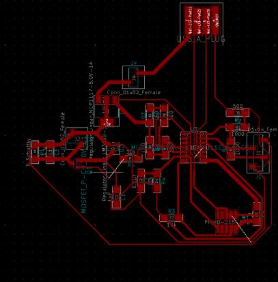
Here is the final schematic, it will be explain after.

After testing the motor with the motor supply, I know that the motor can work with 5V. So I decided to use a 5V regulator with 1A to power the motor system.
For the motor system, I used the system Luc explained us to turn away the current in excess with a diode and a capacitor when the motor stop.

The MOSFET control the current, and allow to flow or not.

To wire the MOSFET I looked for the wiring in the datasheet.

I also took again the different pull down form the previous boards I made during the electronics weeks, and also the JTAG connector to flash the board.
I designed also to have an input, the sonar, this time without making the error to not feed it with 5V. I used a voltage divider bridge, with resitor, to have the signal to go back in the micorcontroller SAMD11C in 3.3V and not in 5V as measured during the input week.

I added a connector with 2 female pins, one to make the bridge when I flash the board in 5V, and in the other case to be able to power the board in 12V. When I want to plug the board with 12V I will power the pin on the 01x02 connector and the ground on the ground. When I want to have 5V I will wire the connector on the 01x02 that is linked to the USB key, to the connector on the 01x05 connector that is link to a 5V, for example when I want to flash the board.

Then I did the traces in the PCB to link everything that needs to be linked. I first tried to postion every components and link everything.
Then I add some 0 Ohm resistors to make the bridhes that miss to be able to connect everything.

And here is the result with board and the traces.

Here I got a problem because I made a bridge with a ground and the software does not detect the bridge with the 0 Ohm resistor. I let the PCB like that and I now that it is not a mistake. The two GND traces are linked with a 0 Ohm resitor.

To have the two pads named GND for the resistor, I added the an extra trace on the schematic, but actually it is not really a trace, link that I make physically.


I exported the two files, one for the traces and one for the outlines in svg file, and I used mods to have the .rml files. Here is the paths for the traces.

And here is the path for the outlines of the board.

When I wanted to do the outline of the baord, mods is doing two paths, one in the interior of the outline, one at the exterior. That’s why I set a very small tool, to not have my board to small, specially on the USB key.

The PCB I stick was not flat enough, that’s why I had to launch the traces file 2 times.

And here is the result of the milling.

Mods
For the outlines, I set a very small tool. We can see the two different paths made, one with a 0.15 mm tool, one with a 1 mm tool.


Soldering and flashing
After milling my board, I soldered all the components.

To know the side of the LED I looked for the datasheet.

I did the same for the diode but I did a mistake, I inverted cathode and anode, I thought cathode was for the 5V power but it was the opposite.


For the regulator, I didn’t find it on the inventory in my lab, I did not soldered and solder a simple wire, with power my power only in 5V with the USB key at that moment.

I flashed the board with the programmer. I flashed it with the programmer I made without having current flowing inside the board, only with the programmer supply current to the SAMD11C.

Acutally, I made a mistake, I flashed the wrong line of code, and we will see in the following, the consequences of this carelessness.

And here starts the problem. I plugged the board to my computer, with the wiring to have 5V supply for the board, and it starts making smoke. I unplugged everything, and looked for where the problem could come from. When I soldered the diode, I did not paid attention of the side of it, and acutally I soldered it on the wrong side. I make a short circuit and all the current goes inside the diode and made it burn.

I desoldered the diode and checked if the board was still working. I tried to flash it again, and it works, both with the Atmel programmer, and my own programmer. But when I opened the Arduino IDE, the software was not able to find the COM where my board was plugged. However, I flashed my board with the help of the Atmel-Ice programmer, and the flashing was successful.


I flashed a basic blink code but the LED didn’t blinked.

Here is the code I flashed to test the board:
// the setup function runs once when you press reset or power the board
void setup() {
  pinMode(14, OUTPUT);
  pinMode(15, OUTPUT);
}

// the loop function runs over and over again forever
void loop() {
  digitalWrite(14, HIGH);
  digitalWrite(15, HIGH);
  delay(1000);
  digitalWrite(14, LOW);
  digitalWrite(15, LOW);
  delay(1000);
}
I checked on the oscilloscope what was going out of the two pins.


And now I supposes that I burned the microcontroller. Because the diode was soldererd on the wrong side, when I put 5V current, it burned the SAMD11C. I tried to desolder the microcontroller to put another one but it was a waste of time, there is too many pins soldered. That’s why I decided to mill another board. I milled a second one with the same file, but the PCB inside the Roland machine was not flat and when I milled it, one of the trace inside the microcontroller has the copper removed.
Design and mill of the board - Second try
I checked with my instructor the logic shematic, and it appears that I wired wrong the pull down with the MOSFET.
For that matter, I redraw my design, with the right schematic, and correct the pull down for the MOSFET with the 10k resistor. I also removed one trace inside the microcontroller to not have too thick trace and avoid the risk of the copper to be removed. I drew again the PCB quickly.
I have too much bridges with 0 resistors but I don’t have time to improve that, I decided to mill it like that.
Here is the board where the copper lines were removed under where the microcontroller is supposed to be.

And during the third milling, I went through many problems. With the help of my instructor, we finally reach to mill the board. The problems were that the milling bit does not go enough deep to cut the PCB, but in the other side, it goes too far. We had to pass many times for the traces cutting, but the more the files is launch, the more the traces get thiner. We finally deleted the first half of the code in the .rml to be able to finish the milling for the part that were not milled. The milling was not very well finished but it will still work a priori.

Here is finally the board with all the components soldered.

I flashed the board with the programmer, on Arduino IDE.

Then I tried to fix all the problem I have. First I flashed the wrong line of code, as we can see on the scrennshot. Here is the right one:
edbg -b -t samd11 -pv -f sam_ba_Generic_D11C14A_SAMD11C14A.bin
Here is the correct line flashed with edbg.

I flash the right .bin file, and I finally reahc to program my board with blinking the two LEDs.

Then with the motor.
I wrote this code to be able to control the motor with the MOSFET.
// the setup function runs once when you press reset or power the board
void setup() {
  pinMode(14, OUTPUT); // red LED
  pinMode(15, OUTPUT); // blue LED
  pinMode(5, OUTPUT); // pin that control the MOSFET that control the motor
}

// the loop function runs over and over again forever
void loop() {
  digitalWrite(14, HIGH); // on the red LED and make the motor turn
  digitalWrite(15, LOW);
  digitalWrite(5, HIGH);
  delay(5000);
  digitalWrite(14, LOW); // on the blue LED and stop the motor
  digitalWrite(15, HIGH);
  digitalWrite(5, LOW);
  delay(5000);
}
I flashed via the programmer.


It always spins and don’t stop.
To understand what is going on, I measured a lot of place with the multimeter.


It might have a short circuit somewhere because of the traces that are very close. I will desolder the connector and the MOSFET, clean the pads, and solder again the components carefully.
When there is the blue LED on it is supposed to spin, when there is the red one ON, it supposed to stop.
I checked the output pin for the SAMD11C. The pin react as the code flashed, when it is HIGH it sends 3.3V to the pin that control the MOSFET, G.


Here is the schematic from the Datasheet of the MOSFET I used.

So the command seems correct to engage the MOSFET.
Now we have to figure out how the MOSFET NDS356AP with P-Channel is working. With my instructor we think to many ways. First we desoldered the diode, and the capacitor and put the MOSFET on the traces, but it didn’t change anything.
We measured the ampers that goes in the motor, but it is always the same amount.


We finally soldered the component on a garbage board, and he soldered wire to it to be able to test the side of the component.

Here is the wiring.

He finally told me that I might have wire it wrong, and switch the D and the S on the MOSFET.
We reach to plug it to the correct way, with a gate that control the current, and D and S for the GND and the VCC.
Here is the PNP MOSFET. The G, Gate is the wire that I move. The D, is plugged to the GND, and the S receive 5V.
Then we tested a NPN MOSFET, the gate is still the same wire, but this time, the S is plugged to the GND and D receive 5V, as I did on my shematic.

I will solder this MOSFET on my board. When the gate receive the signal, 5V it trun on the motor, and when receive nothing, the GND, it stops.
There is two kinds of MOSFET, a PNP and a NPN. To design the board and when I soldered it, I made the mistake of not consider that. After all the test we made, I finally understood the difference between the two kind of MOSFET. The Gate, G stay the same, it is the command to activate the MOSFET, but the D and the S are inverted depending on the MOSFET.
I finally switch the MOSFET on my board, to have a NPN MOSFET, because the design I did was made for it and not the one I soldered at the beginning. Here it works better.
The last problem I have is the capacitor I solder. I soldered a 0.1 µF capacitor, but it was too much for the motor, it takes all the current. After making some test with differents capacitor, I chose to solder a 10 PF capacitor, because it makes the motor turn well.
And finally the motor turns according to the code flashed previously, with all the components soldered.