"Hi everyone ,Week 14 Networking and communications.This week is realy important as my project point of view.Since i am thinking of to establish a wi-fi network for my board and talked to web server.So i am looking to finish it.
- Send a message between two projects
Group assignment
- Design, build, and connect wired or wireless node(s) with network or bus addresses
- Build
- Connect
- Wired or wireless node(s)with network or bus addresses
Individual assignment
Table of Content
- Types of communication
- About serial communication
- Synchronous Serial Protocols
- Asynchronous Serial Protocols
- Designing Attiny 45 bridge and node boards for asynchronous serial communication
- Schematic of bridge & nodes boards
- Board layout of bridge & nodes boards
- Milling & soldering of Bridge & nodes boards
- Programming Attiny 45 bridge & node boards
- Test the communication between Atiny 45 bridge & node boards
- Asynchronous Serial Communication With AT Commands
Project work:
Types of Commuincation protocols
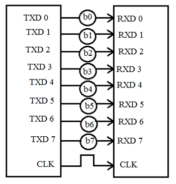
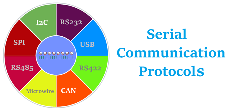
There are different types of data transfer available in the digital electronics such as serial communication and parallel communication. Similarly the protocols are divided into two types such as Serial Communication Protocol and Parallel Communication Protocols. Examples of Parallel Communication Protocols are ISA, ATA, SCSI, PCI and IEEE-488. Similarly there are several examples of Serial Communication Protocols such as CAN, ETHERNET, I2C, SPI, RS232, USB, 1-Wire, and SATA etc.
Two types of communication
1. About Serial Commuincation Protocols
What is serial communication Protocol?
Before starting with Serial Communication Protocols, Let’s break the terminology in three parts. The communication is very well known terminology which involves the exchange of information between two or more mediums. In embedded systems, the communication means the exchange of data between two microcontrollers in the form of bits. This exchange of data bits in microcontroller is done by some set of defined rules known as communication protocols. Now if the data is sent in series i.e. one after the other then the communication protocol is known as Serial Communication Protocol. More specifically, the data bits are transmitted one at a time in sequential manner over the data bus or communication channel in Serial Communication. Refer from circuitdigest.com
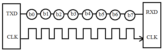
1.1 Synchronous Serial Communication
1.1.1 SPI Protocol
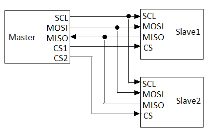
Communication in SPI is done by a master and slave relationship, in which master initiates data frame. When the master generates the clock and selects a slave the data can be transferred either in one or in both the direction simultaneously.
 Reference:www.signoffsemi.com
1.1.2 I2C Serial Communication
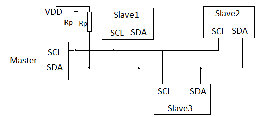
I2C interface is a simple bidirectional interface which uses a single data line to transmit and receive the data. I2C is a serial 2 wire bus designed to communicate between the IC’s using a minimum number of pins. It is half duplex, synchronous serial communication protocol. The data transmission always initiated by the master. Each device on the I2C bus has a specific device address to differentiate between other devices that are on the same I2C bus. The I2C interface consists of a Serial Clock Line(SCL) and Serial Data Address(SDA). Data transfer may be initiated only when the bus is idle. A bus is considered idle if both SDA and SCL lines are high after a STOP condition. I2C supports transfer speed of around 100kHz (original standard, or 400kHz using the most recent standard).
2.1 Asynchronous serial communication
In asynchronous Serial Interface, the external clock signal is absent. The Asynchronous Serial Interfaces can be seen in mostly in long distance applications and are a perfect fit for the stable communication. In asynchronous Serial Interface the absence of external Clock Source makes it rely on several parameters such as Data Flow Control, Error Control, Baud Rate Control, Transmission Control and Reception Control. On the transmitter side, there is a shifting of parallel data onto the serial line using its own clock. Also it adds the start, stop and parity check bits. On the receiver side, the receiver extracts the data using its own clock and convert the serial data back to the parallel form after stripping off the start, stop, and parity bits. The well-known examples are RS-232, RS-422 and RS-485.
2.1.1 RS232
What is RS232 Protocol?
The RS232 (Recommended Standard 232) is very common protocol used to connect different peripherals such as Monitors, CNCs etc. The RS232 comes in male and female connectors. The RS232 is point-to-point topology with maximum one device connected and covers distance up to 15 meters at 9600 bps. Information on the RS-232 interface is transmitted digitally by logical 0 and 1. The logical "1" (MARK) corresponds to a voltage in the range from -3 to -15 V. The logical "0" (SPACE) corresponds to a voltage in the range from +3 to +15 V. It comes in DB9 connector which has 9 pinouts such as TxD, RxD, RTS, CTS, DTR, DSR, DCD, GND.
Types of Serial Cables
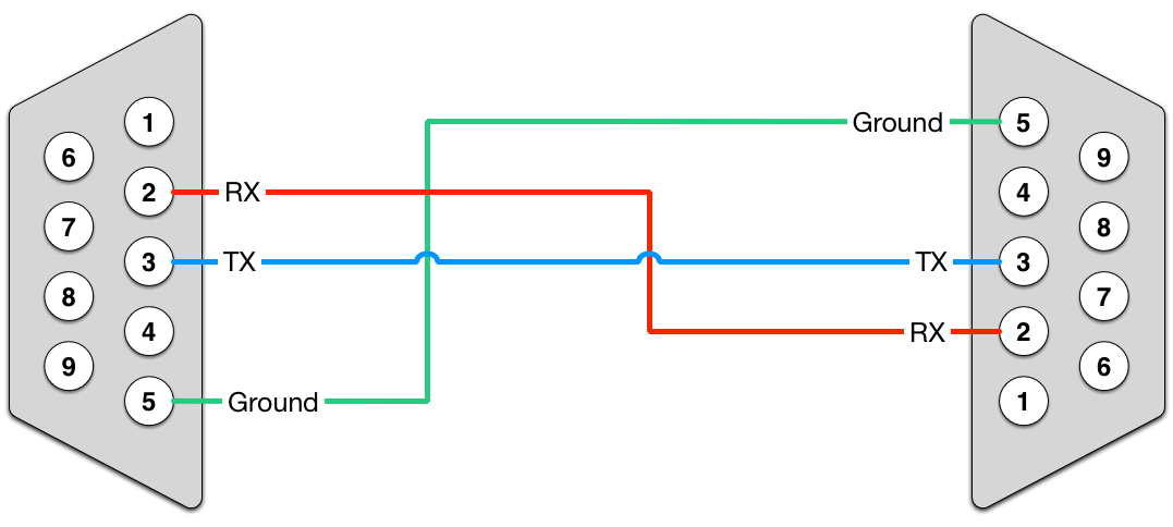
To make serial communication possible between DTE and DCE, two types of RS232 cables exist. They are Null modem and Straight-cable. In null modem cable, the TX (Transmitter) pin of the male connector is linked up with the RX (Receiver) pin of the female and the RX pin of the male is connected to TX pin of the female.
How RS232 Communication Works?
The working of RS-232 can be understood by the protocol format. As RS-232 is a point-to-point asynchronous communication protocol, it sends data in a single direction. Here, no clock is required for synchronizing the transmitter and receiver. The data format is initiated with a start bit followed by 7-bit binary data, parity bit and stop bit which are sent one after another.
What is Handshaking?
Handshaking is the process which is used to transfer the signal from DTE to DCE to make the connection before the actual transfer of data. The messaging between transmitter & receiver can be done by handshaking.
The connectors DB9 and Db25 are used for handshaking purpose. When no handshaking is performed, only the TxD (Transmitter) and RxD are cross-coupled. Other pins, RTS, CTS, DSR, and DTR are connected in loopback fashion.
To use the handshaking technique, RTS and CTS are cross-coupled. Also, DTR and DSR are also connected in cross mode.
Why to use Handshaking?
To send and receive the information without loss of data, it is necessary to maintain robust communication between the transmitter and receiver. To do that, buffer is used. Buffer is a temporary storage location which allows the transmitter and receiver to store the data until the information is processed by each other at different speeds.
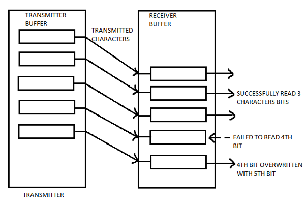
As shown in above figure , If the transmitter sends data at a higher speed, the receiver may fail to receive. In this case, character ‘C’ is missed by the receiver. To avoid this, handshaking is used. Handshaking allows the transmitter and receiver device to agree before the communication is going to start.Refer from https://www.codrey.com/embedded-systems/rs232-serial-communication/
2.1.2 RS422
The RS422 is similar to RS232 which allows to simultaneously send and receive messages on separate lines but uses a differential signal for this. In the RS-422 network, there can only be one transmitting device and up to 10 receiving devices. The data transfer speed in RS-422 depends on the distance and can vary from 10 kbps (1200 meters) to 10 Mbps (10 meters). The RS-422 line is 4 wires for data transmission (2 twisted wires for transmission and 2 twisted wires for receiving) and one common GND ground wire. The voltage on the data lines can be in the range from -6 V to +6 V. The logical difference between A and B is greater than +0.2 V. Logical 1 corresponds to the difference between A and B less than -0.2 V. The RS-422 standard does not define a specific type of connector, usually it can be a terminal block or a DB9 connector.
2.1.3 RS485
Since RS485 uses multi-point topology, it is most used in the industries and are industry preferred protocol. RS422 can connect 32 line drivers and 32 receivers in a differential configurations but with the help of additional repeaters and signal amplifiers up to 256 devices. The RS-485 does not define a specific type of connector, but it is often a terminal block or a DB9 connector. The speed of operation also depends on the length of the line and can reach 10 Mbit / s at 10 meters. The voltage on the lines is in the range from -7 V to +12 V. There are two types of RS-485 such as half duplex mode RS-485 with 2 contacts and full duplex mode RS-485 with 4 contacts.
2.1.3 1-Wire
Dallas Semiconductor's 1-Wire bus is an asynchronous, master/slave bus with no protocol for multi-master. Like the I2 C bus, 1-Wire is half-duplex, using an open-drain topology on a single wire for bidirectional data transfer. However, the 1-Wire bus also allows the data wire to transfer power to the slave devices, although this is somewhat limited. Though limited to a maximum speed of 16Kbps, bus length can be upwards of 1,000 feet, given the proper pull-up resistor. For more detail on the 1-Wire bus, read H. Michael Willey's “One Cheap Network Topology” (January, 2001).https://www.embedded.com/serial-protocols-compared/
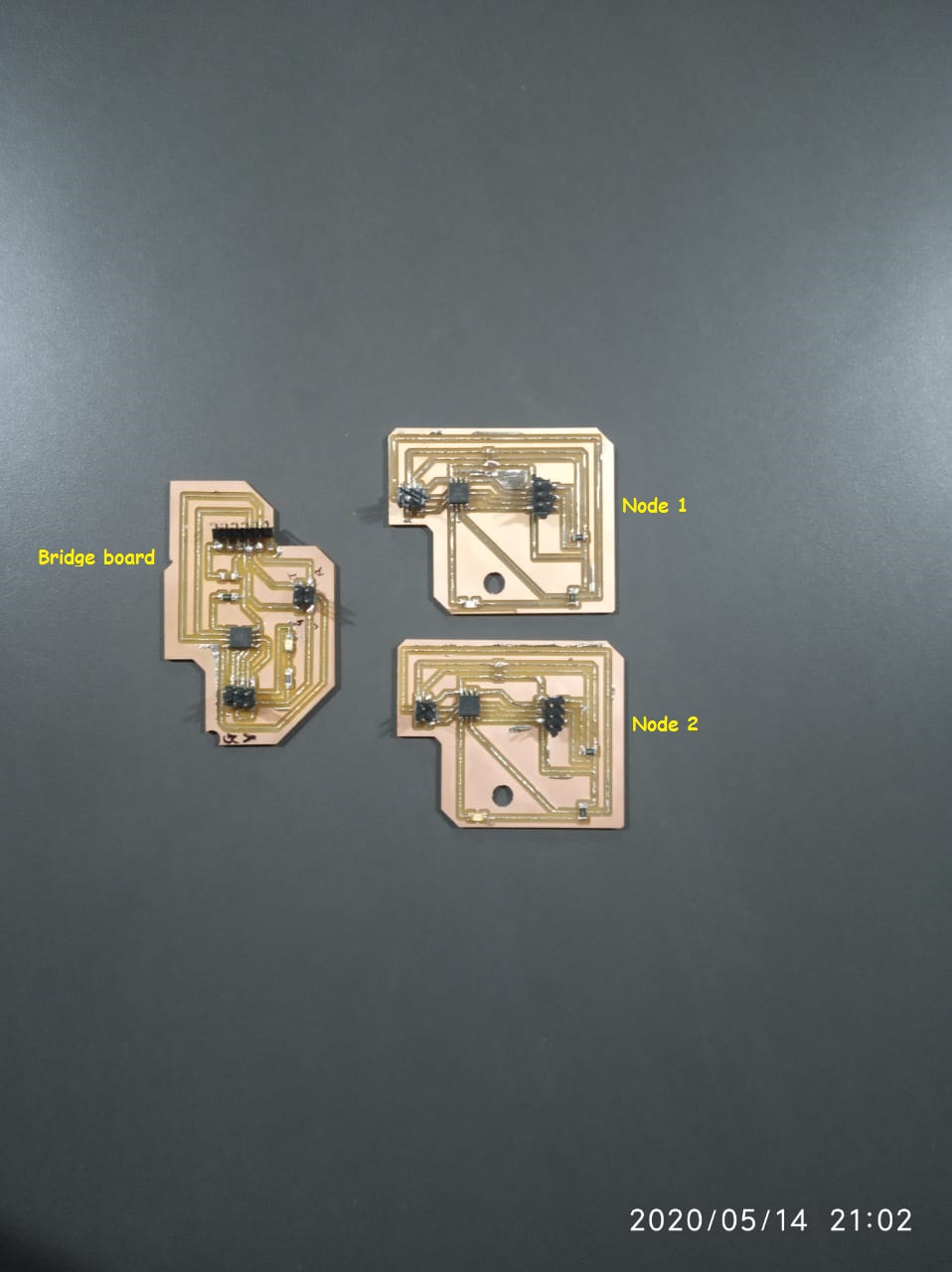
Designing Attiny 45 bridge & node boards for asynchronous serial communication
For the networking and communication week,I decided to learn asynchronous communication between One Bridge and two node.For that i made one Attiny 45 bridge and two Attiny 45 as node .Lets go to design it......
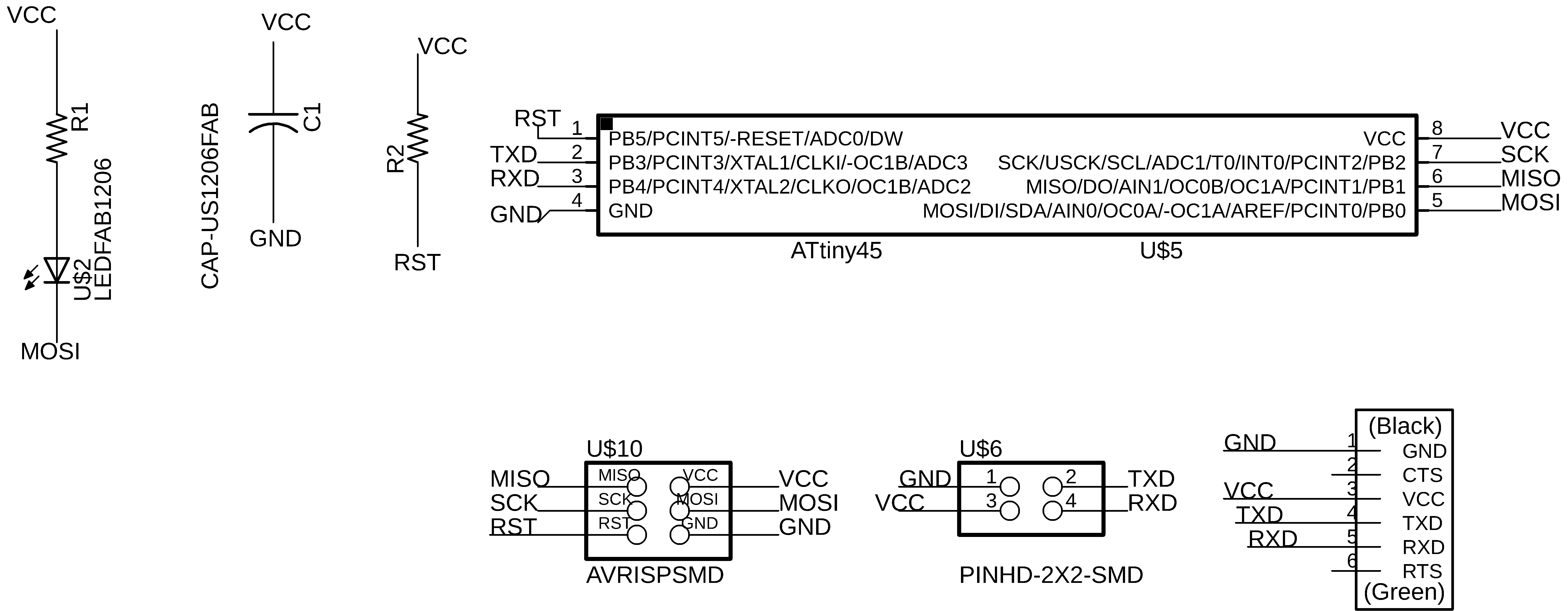
Schematic of Attiny 45 as Bridge
I referred the Neil document and redesign the attiny 45 board as a bridge.
EAGLE → Projects > eagle > Bridge attiny45
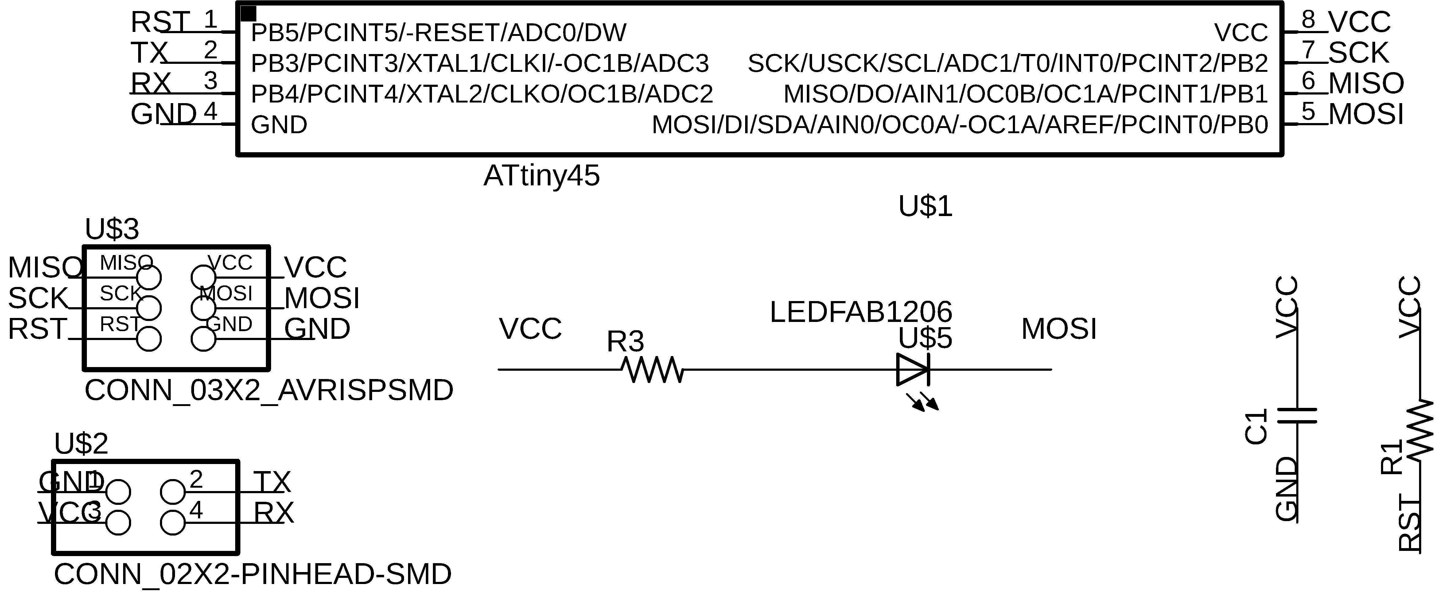
Schematic of Attiny 45 as Node
I referred the Neil document and redesign the attiny 45 board as a node.
EAGLE → Projects > eagle > Node attiny45
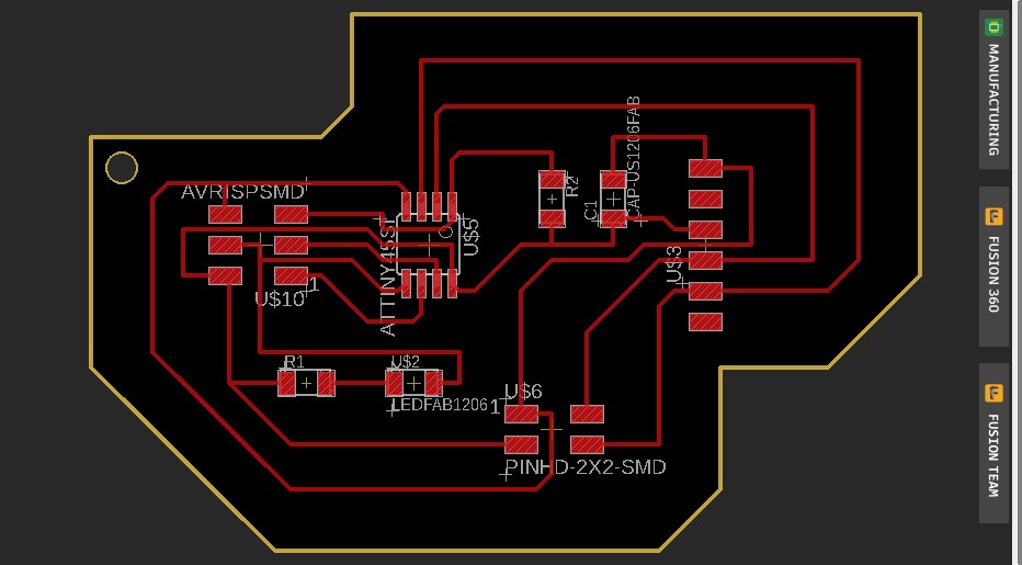
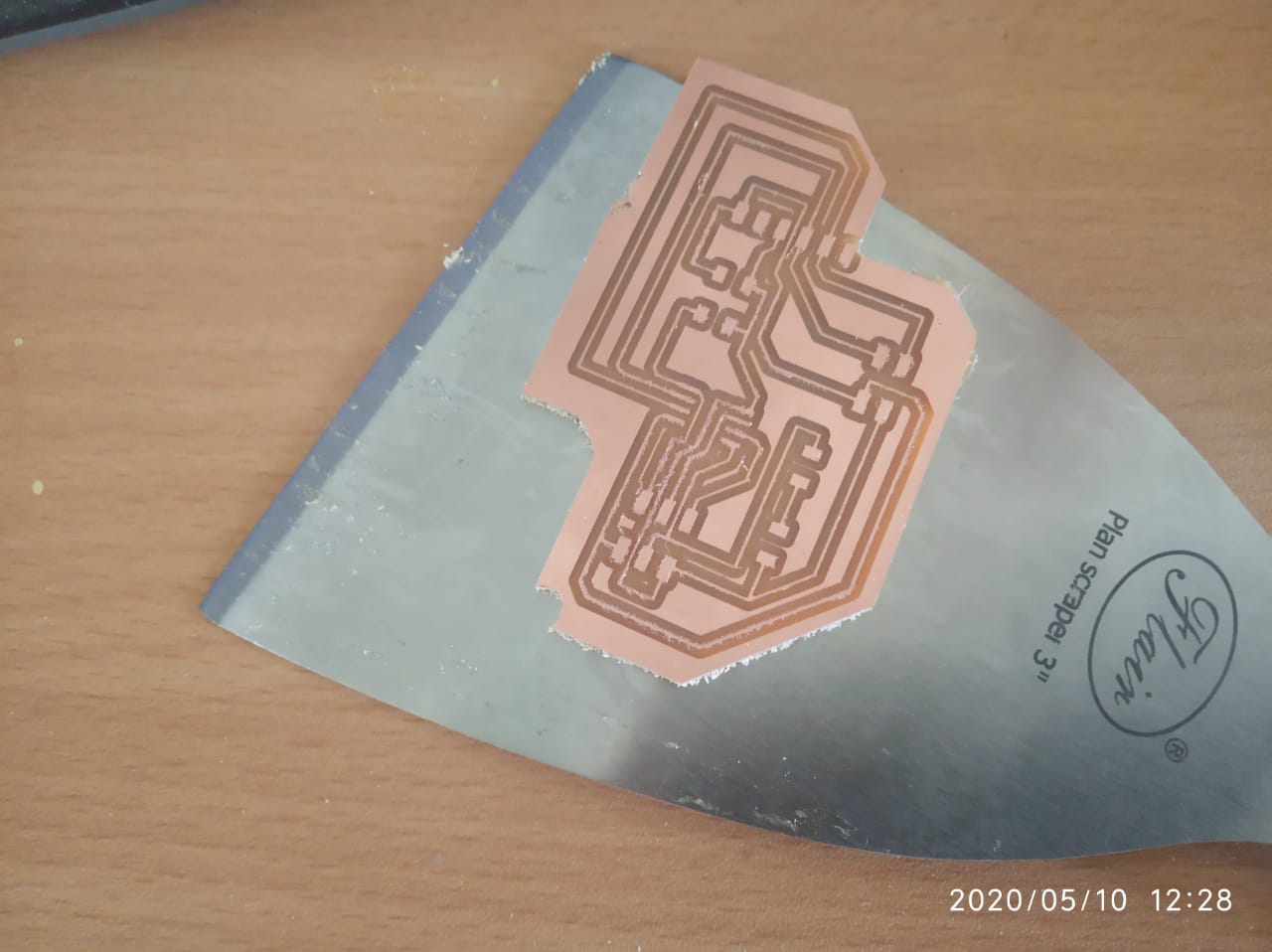
Board layout of Attiny 45 as bridge & nodes
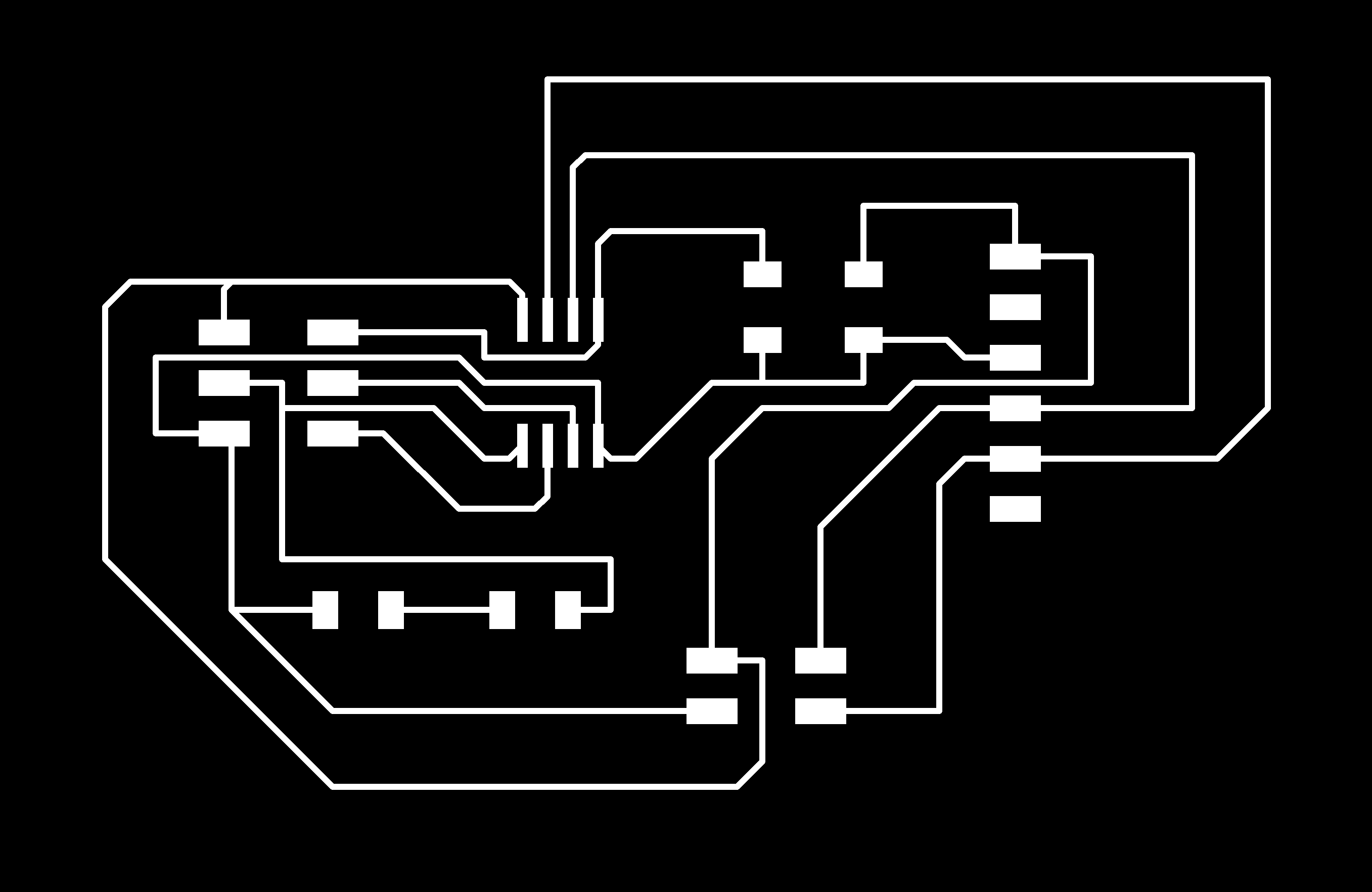

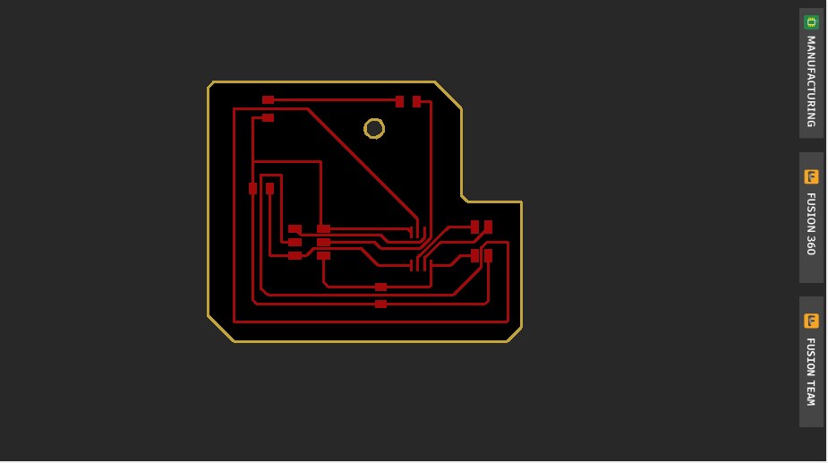
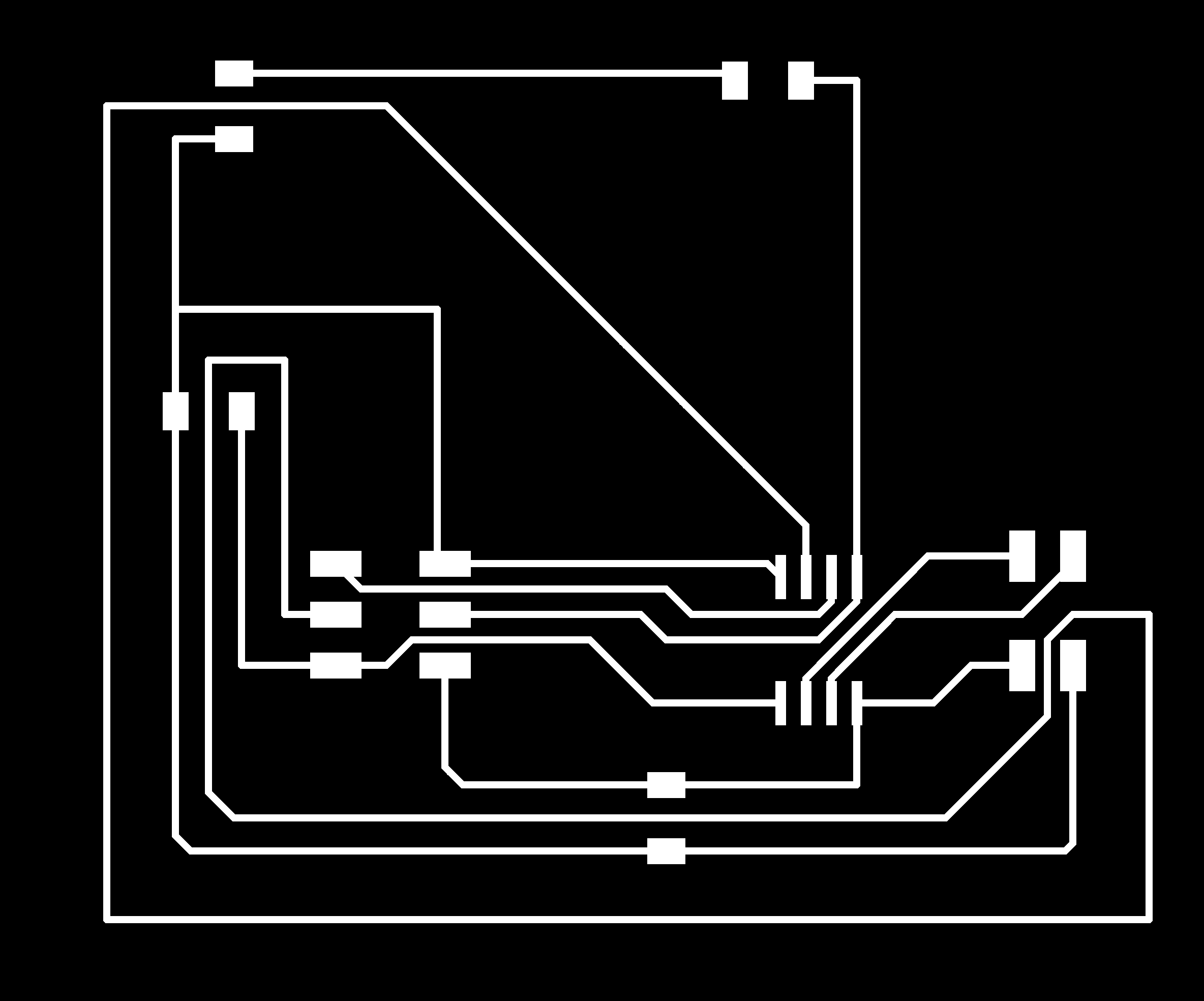
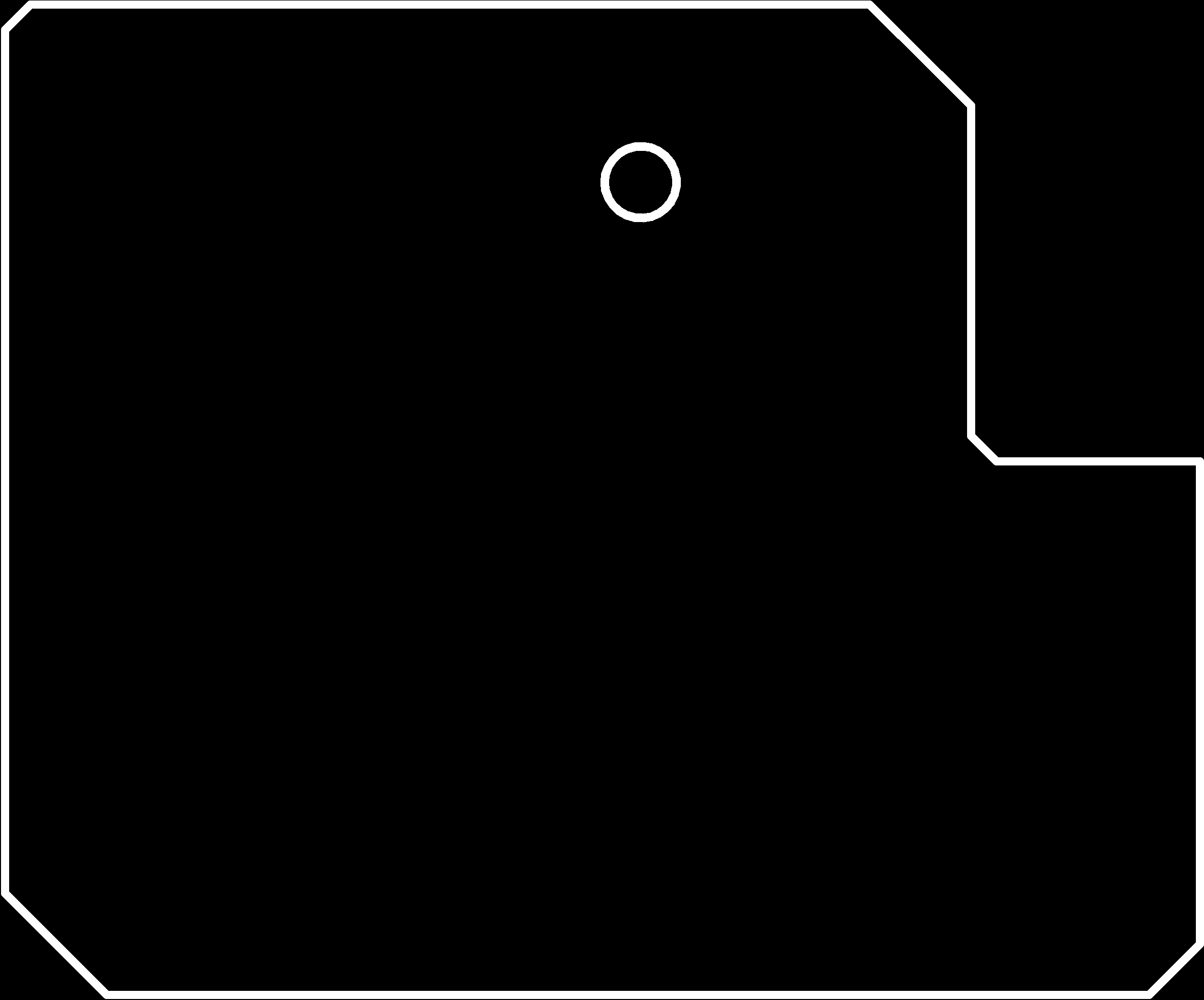
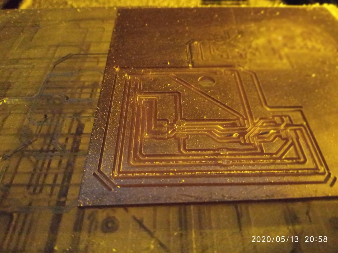
PCB Milling of Attiny 45 bridge
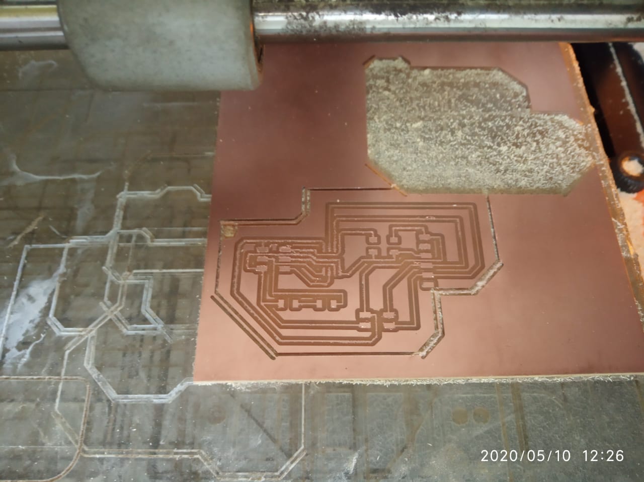
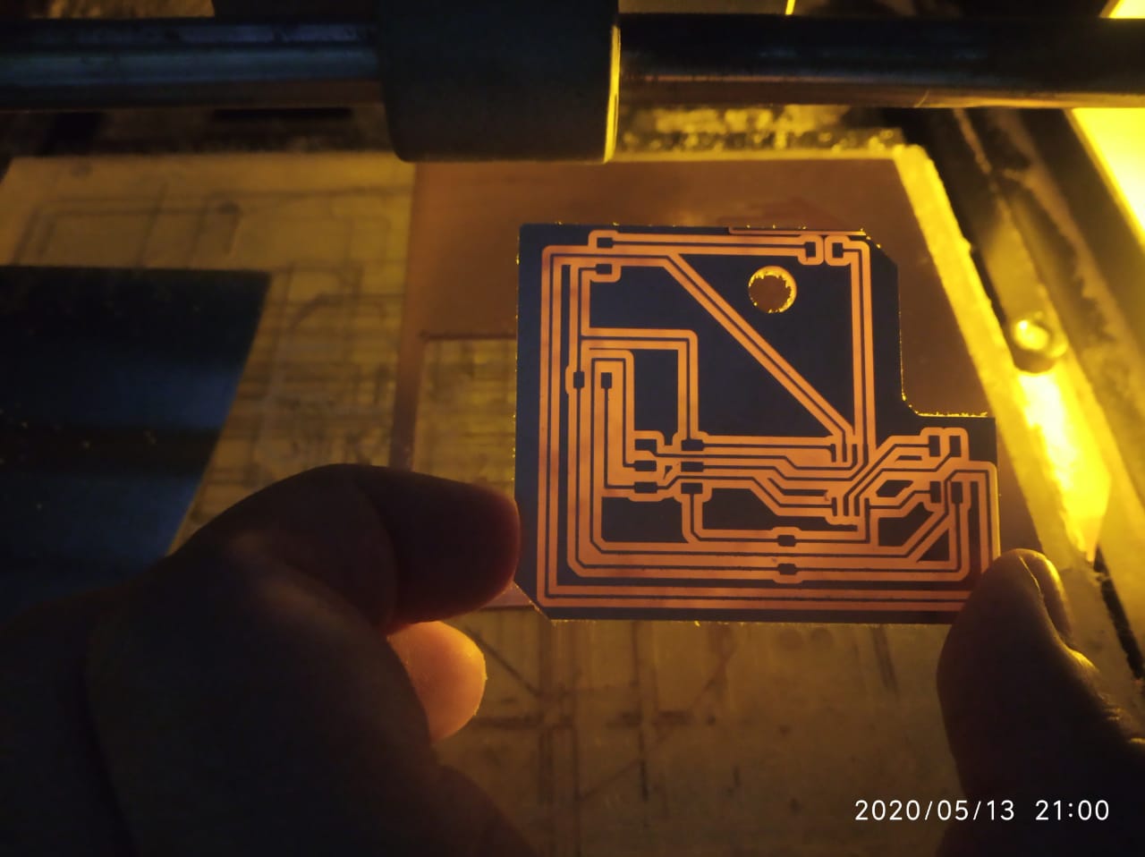
PCB Milling of Attiny 45 node
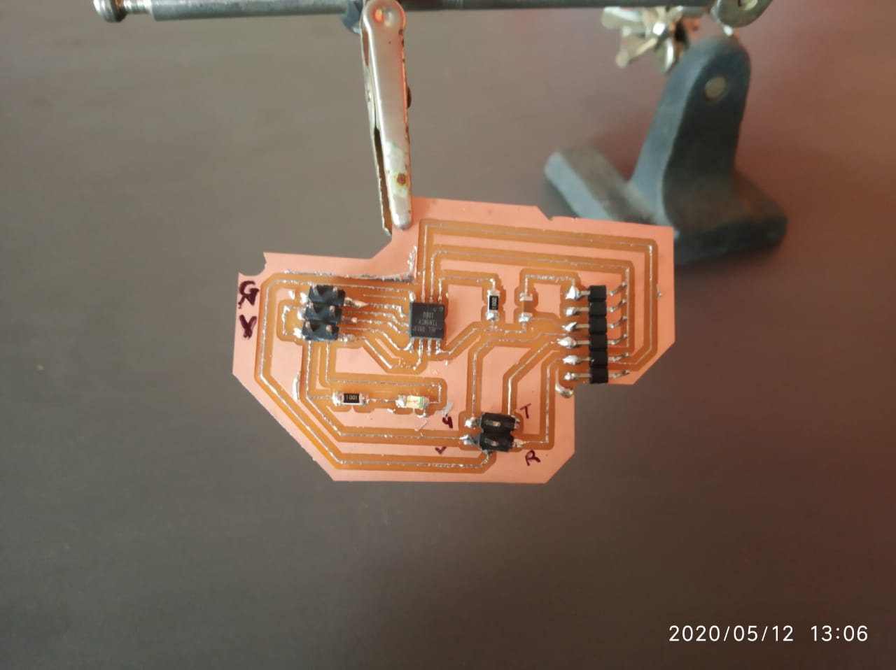
Soldering and stuffing Attiny 45
Programming Attiny45 bridge boards
Programming Steps for bridge board
Do Hardware arrangement:
Write Arduino code for bridge board
#include "SoftwareSerial.h"
#define node '0' // defined bridge board address 0
const int rx=PB4;
const int tx=PB3;

// the setup function runs once when you press reset or power the board
SoftwareSerial mySerial(rx, tx);

void setup() {
  // initialize digital pin 13 as an output.
   mySerial.begin(9600);
  pinMode(PB0, OUTPUT);
  digitalWrite(PB0, HIGH);
}

// the loop function runs over and over again forever
void loop()
{
  if(mySerial.available() > 0)

  {

    int x=mySerial.read();
    delay(1000);


  if (x==node)
    {
    digitalWrite(PB0, LOW);   // turn the LED on (HIGH is the voltage level)
    delay(500);
    digitalWrite(PB0, HIGH);
    delay(500);

        }
  }
}
Programming Steps for node board
Write Arduino code for node board
#include "SoftwareSerial.h"
#define node '1' // defined bridge board address 1
const int rx=PB4;
const int tx=PB3;

// the setup function runs once when you press reset or power the board
SoftwareSerial mySerial(rx, tx);

void setup() {
  // initialize digital pin 13 as an output.
   mySerial.begin(9600);
  pinMode(PB0, OUTPUT);
  digitalWrite(PB0, HIGH);
}

// the loop function runs over and over again forever
void loop()
{
  if(mySerial.available() > 0)

  {

    int x=mySerial.read();
    delay(1000);


  if (x==node)
    {
    digitalWrite(PB0, LOW);   // turn the LED on (HIGH is the voltage level)
    delay(500);
    digitalWrite(PB0, HIGH);
    delay(500);

        }
  }
}
Interface bridge & nodes
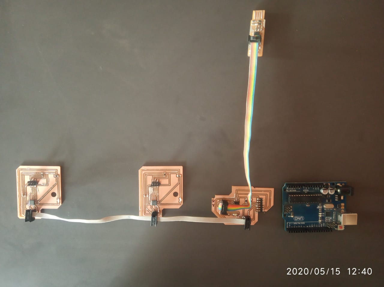
Test the communication between Attiny 45 bridge & nodes
Test1:
In above video i have shown you one bridge and one node board only.Actually i have milled two node but unfortunately at this movement one node is not working.
Error correction:I checked all the connection of second node board once again and what i found that , the LED which i used on my board didnt get powered since the resistor is not soldered properly.I fixed this issue and test it successfully.Now ready to test two nodes and one bridge.
After programming bridge and nodes boards seperately now the time to test them .So Connect the three hello.bus.45 boards using the data cable and then
Group assignments
For this week group assignments i have decided to do communication with Atmega 328p with local webserver.Actually i want to learn this wireless communication for project work as well.So i choose this task for myself as part of group assignments.
Asynchronous Serial Communication With AT Commands
In this tutorial I am going to show you how to set up the ESP-01 Wi-Fi module, how to configure it, and then verify it.In short i want establish communication between the module and another board.
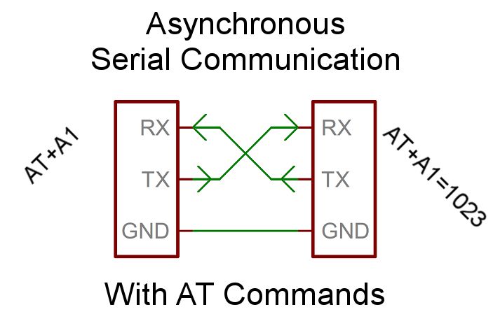
The advantage of Asynchronous Communication is that you don't need the communication being done in sequence, mainly when you define the request code but not the receiving code.Refer from:(https://www.instructables.com/id/Asynchronous-Serial-Communication-With-AT-Commands/)
In the first option, you’re using the Module as an add-on and writing code in the Arduino to talk to it. The other model is that you’re trying to work on the module directly to program it or upgrade it. For our final project here we will have code on the Arduino talking to the module, but to make sure everything is working we’ll be talking to the Module directly (kind of). More on that later.
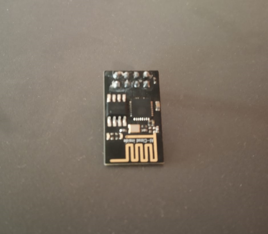
About ESP 01
he ESP8266 ESP-01 is a Wi-Fi module that allows microcontrollers access to a Wi-Fi network. This module is a self-contained SOC (System On a Chip) that doesn’t necessarily need a microcontroller to manipulate inputs and outputs as you would normally do with an Arduino, for example, because the ESP-01 acts as a small computer. Depending on the version of the ESP8266, it is possible to have up to 9 GPIOs (General Purpose Input Output). Thus, we can give a microcontroller internet access like the Wi-Fi shield does to the Arduino, or we can simply program the ESP8266 to not only have access to a Wi-Fi network, but to act as a microcontroller as well. This makes the ESP8266 very versatile, and it can save you some money and space in your projects. In this tutorial we are going to show you how to set up the ESP-01 Wi-Fi module, configure it, and verify that there is communication established between the module and another device & talked to web server as well.
Pin configuration:
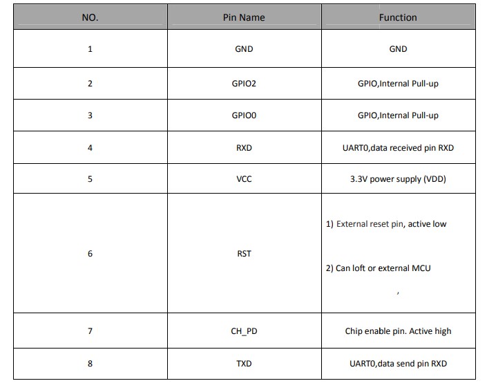
Next, we have the Pinout connections. Depending on the article you’re looking at the connections will change. It’s important to understand the pins and how they’re used. In general, you have a VCC for power and your common GND. You also have TX and RX to transmit and Receive. You have two GPIO pins, a reset pin, and a CH_PD pin. This board is designed to be an add-on to another micro-controller and offers a feature for being able to turn it on or off by setting the CH_PD pin from High to Low. In my case, I’m going to leave it on all the time so I’m just pulling high all the time.
CH_PD is a chip controlled power down and needs to pull high in order to run Speaking of voltage, all the articles I’ve seen warnings not to give it too much power, but mine seemed to need more than the 3.5v Arduino served up. In my tests, the module wouldn’t start up correctly with 3.5v which made it very difficult to debug early on. I ended up switching to the 5v pin and everything has been great.
Hardware requirments
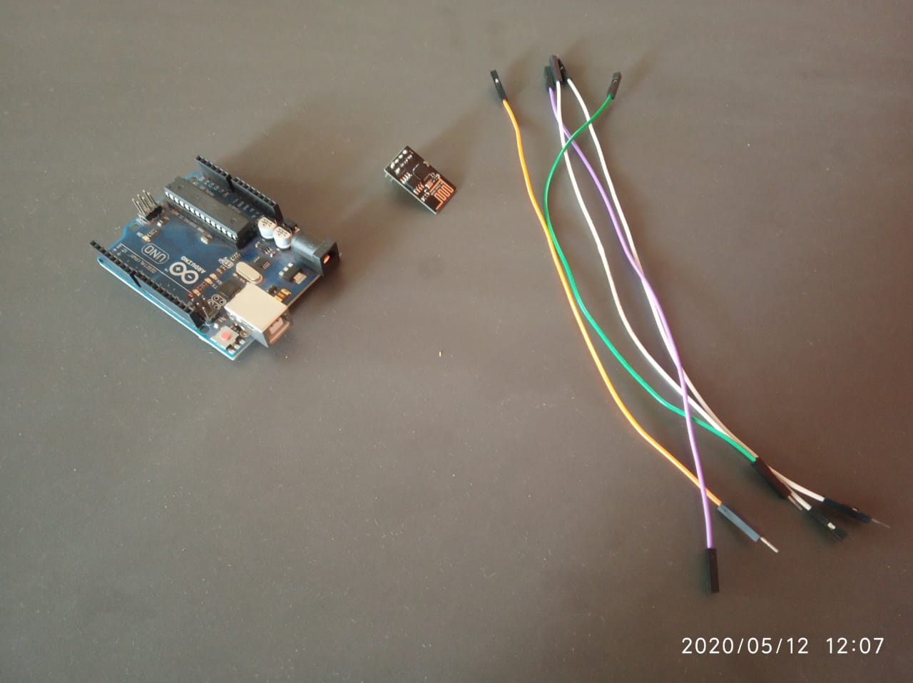
Interface Arduino with ESP 01
Arduino -- ESP-01
Follow these steps.
Establish WI-Fi for Arduino through ESP -01
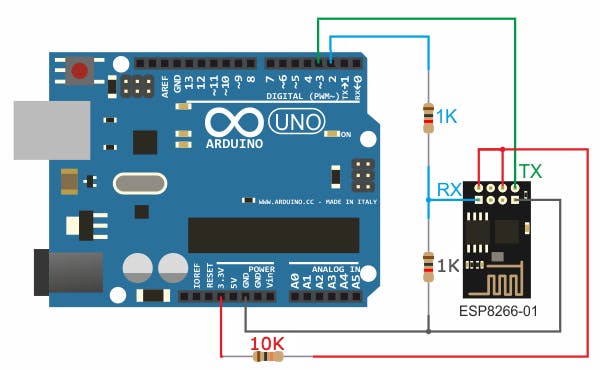
In the circuit there are 2 resistor one of 1k ohm and the other one of 2.2k ohm. The two resistors are used to step down the 5V which comes to arduino into about 3.43V which goes to the ESP-01 board (connected to RX pin of the ESP-01) because the ESP8266EX chip works with 3.3V only and applying a 5V directly may damage it. On the other hand, the TX pin of the ESP-01 is connected directly to the Arduino board without any voltage level converter because here the ESP-01 sends data (at 3.3V) to the Arduino board using this pin.
Note:There is other ways to build a programmer for the ESP-01 module for example by using FT232RL USB to serial converter from FTDI Chip
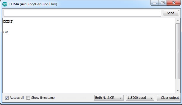
Run AT commands to establish a wi-fi environment for arduino
open the serial monitor and type the following command: You should get an “OK” response. This means that the module is working and that you are good to go. Now we are ready to test a two way communication between the module and another device.
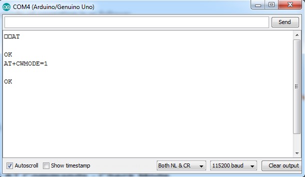
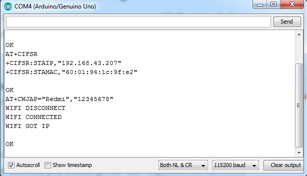
In this tutorial, we are going to set the module to operate in STA mode by typing the following command:
Once we have the ESP-01 operating in STA mode, we need to connect to a Wi-Fi network. First we can check if we are already connected to one by sending the command:
his will display the station IP address of our ESP-01 module.
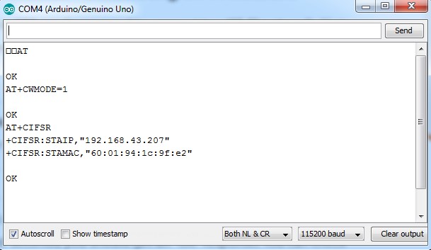
If you don’t get an IP address after entering the previous command, use the following command to connect to your network:
Type the name of your Wi-Fi network and the password to connect to it. Make sure you include the quotation marks. After a couple of seconds, you should get an "OK" response. >
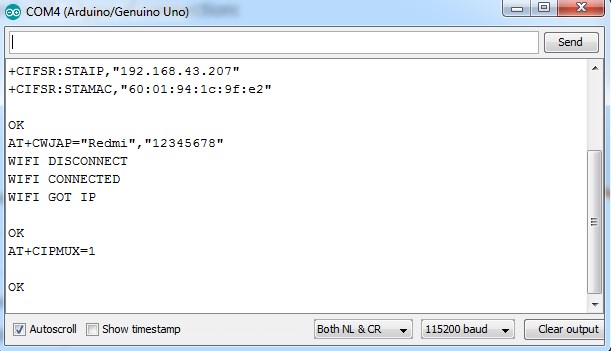
Then we need to enable multiple connections before we can configure the ESP8266 ESP-01 module as a server. Type the next command:
Once again, each number is associated with a type of connection: Single = 0 Multiple = 1
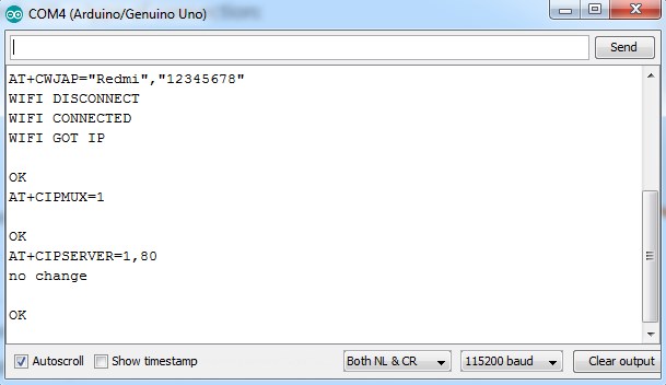
The following step is to start the server at port 80:
The first number is used to indicate whether we want to close server mode (0), or open server mode (1). The second number indicates the port that the client uses to connect to a server. We chose port 80 because this is the default port for HTTP protocol.
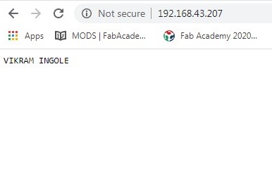
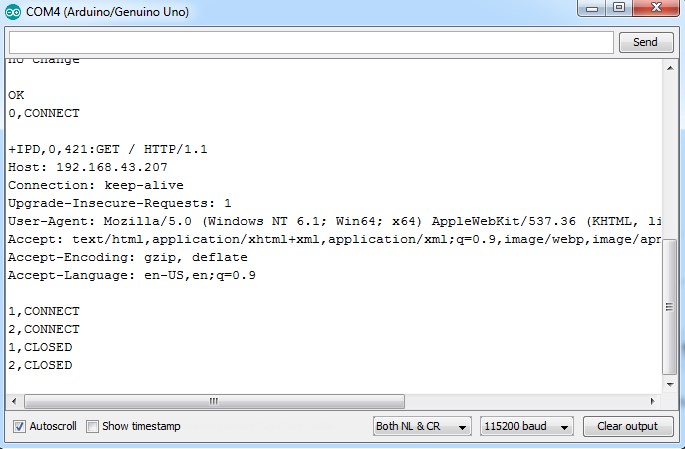
Now, when we open a web browser and type the IP address of our ESP module we get the following response as shown in the image above. This is the HTTP request that our computer sends to the server to fetch a file. It contains some interesting information such as what file you want to retrieve, name of the browser and version, what operating system you are using, what language you prefer to receive the file in, and more.
We can now use the following commands to send some data and display it in our web browser’s window:
The “0” indicates the channel through which the data is going to be transferred; while “15” represents the number of characters that are going to be sent. When we hit enter, the symbol “>” appears. This indicates that we can now type the characters that we want to send to the browser. In this example we chose “VIKRAM INGOLE.”
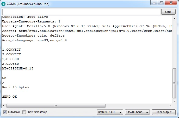
Once we hit enter, our message is displayed on the web browser’s window as shown in the image above.