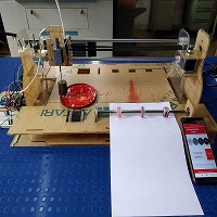
"Hi everyone ,Machine design week we actually all are working hard since two three weeks back.In this week we are going to make a machine called as "Azarkh" Block printing machine.As The Representatives Of Our Precious Heritage, Indian Handlooms Are Known World Over For Their Richness, Variety And Quality. Since Our Country Has Always Been Associated With Rich Weaves, And Unique Textiles, Our Love For Colours And Prints Is Legendary. What Gives Our Fabrics Their Unique Identity Is The Prints And Weaves That Are So Unique To The Region.So we took this idea to make automatic block printing machine for this arts.
- For the machine week our instructor distribute the task for us.So my task was to make following things
- End effector- solenoid valve testing
- Testing of stepper motor
- Assembly check:Holder,stamp,design
- Build a electronic circuits for whole machine
- Roller mechanism (y-axis mechanism)
Task assign to me for machine building week:
Go to Group assignment:
Table of Content
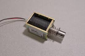
About solenoid valve
A solenoid is a type of electromagnet whose purpose is to generate controlled magnetic field. In this case, when electric current starts flowing through the wire, it produces magnetic field inside the iron core. More the number of turns of coil, more is the magnetic field produced within the wire. When the coil of the solenoid is energized with current, the core moves to increase the flux linkage by closing the air gap between the cores. The movable core is usually spring-loaded to allow the core to retract when the current is switched off.
Details:
Why solenoid valve?
Ok, the reson to used solonoid valve in our machine was that , we want a device who can go down and punch the platform and come back to original position.So we need this kind of action for stamping the color on the material provided on the platform.Click here to see expected action from solnoid valve.
BOM
So after getting sure with concept i have decided to purchase solonoid valve.Details are given below.
| Sr.No. | Componant | Price | Brought from |
| 01 | Solenoid valve | 8$ | thinkrobotics |
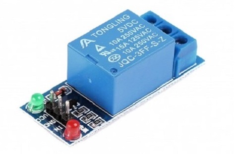
| 02 | Relay 12V | 3.67$ | Amazon |
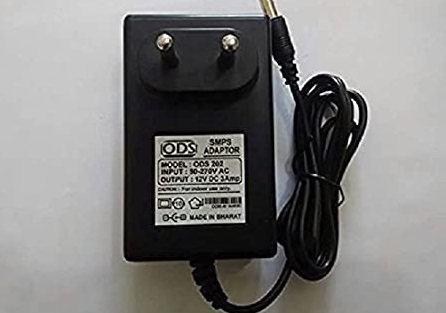
| 03 | Power supply | 04$ | Amazon |
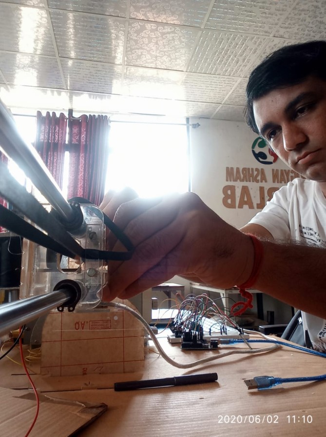
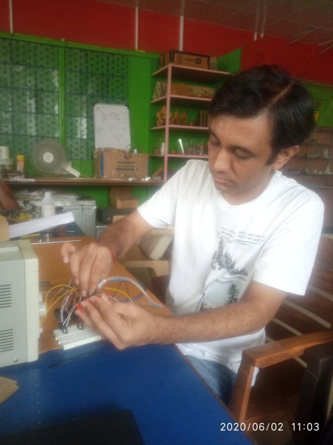
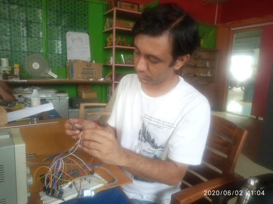
Connection & Testing
How i controlled solonoid using arduino
When you allow a lot of current through coil the levar get updown.Actually it consume a lot of current so when i thought to used arduino it cant provide enough current to work and really its a huge comcern for me.So i decided to used relay board for this.Again while going to used relay we need to see specification over the relay as well.
What you need?
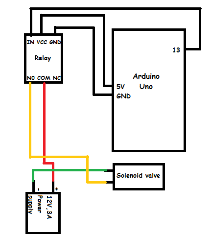
Interfacing diagram of Solenoid valve through relay with Arduino UNO
In this section i have shown the block diagram of how to control solenoid valve through relay with Arduino UNO.In which the pin 13 of arduino UNO is caonneccted to INPUT pin of relay and 5V ,GND is connected to VCC &GND of relay respectively.
Solenoid valve has two pins out of that one pin is connected negative terminal of power supply.Another pin of solenoid valve is conneted to NO pin of relay.COM pin of relay is connted to positive terminal of power supply.
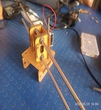
Designing platform for solenoid valve
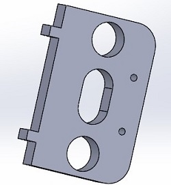
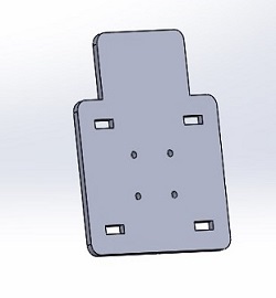
Sketch in solidwork
Once i tested solenoid valve using arduino next task was that to design a platform to hold solenoid valve properly.For that i start designing it on solidwork and here are the left plate anf front plate design in solidwork.
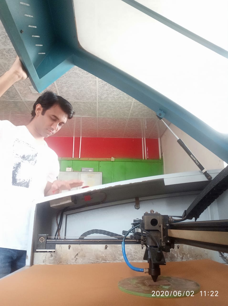
To ensure this design works or not first we decided to go with cardboard using laser cutter and tried to assembled it.It works absoultely fine.
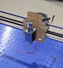
Testing of stepper motor
In this section i am going to test a stepper motor which i need to move the solenoid valve assembly to left and right.
What i Need
BOM
| Sr.No. | Componant | Price | Brought from |
| 01 | Nema 17 | 11$ | RoboKitsIndia |
| 01 | stepper motor driver | 04$ | Robu |
Interfacing diagram of stepper motor with driver
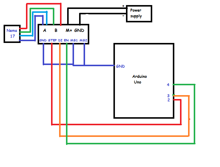
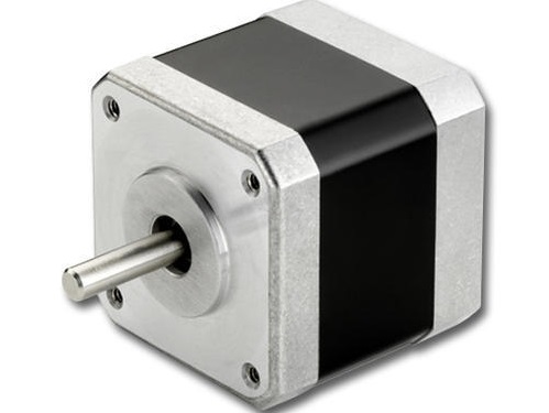
To move the sliding bar left to right and vice-versa i am using a NEMA 17 stepper motor.Arduino uno is used to control the movement of stepper motor.I purchase a NEMA 17 stepper motor from ROBU.
NEMA17 4.2Kgcm Stepper Motor for high torque applications. Ideal Motor for ATM machines, 3D printers, Peristaltic pumps and job positioning and rotating applications. Standard NEMA 17 frame size. 4.2Kgcm bipolar configuration motor.
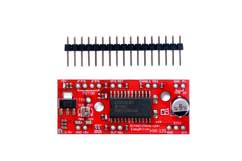
To run a stpper motor i also used motor driver which provide greater flexibility and control over your stepper motor .I am using EASY DRIVER which is compatible with most microcntroller(Arduino Uno) that can output a digital 0V to 5V .This module require a 7V to 30V power supply for a motor.
EasyDriver drives bi-polar motors and motors wired as bi-polar. i.e. 4, 6 or 8 wire stepper motors. The microstep select (MS1 and MS2) pins of the A3967 are broken out allowing adjustments to the micro-stepping resolution. The sleep and enable pins are also broken out for further control.
How to run stepper motor with motor driver?
Test Run on machine?
Complete Interfacing diagram of machine
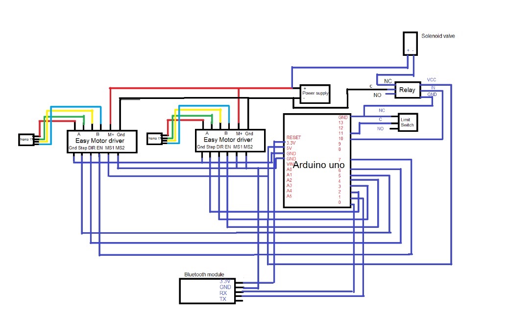
Finally i am ready with my all componants and overcome the issues.Now the time is to interfaced all of these.As our machine need to perform different actions accordingly we used required things.Here i have shown you the complete block diagram of it.In this i have shown you the interfacing of stepper motor through motor driver to arduino uno microcntroller.In this i used two stepper motor and driver as well.One motor will drive the sliding bar left to right and vice-versa .Second motor will be used to move the paper / cloth material on platform .Also i have shown you the connection between solenoid valve through relay.
In the following diagram i also shown bluetooth interfaced with arduino uno.Actually we are controlling our machine through mobile operated bluetooth.
Complete interfacing circuit diagram of machine
Final Test Run video
In this part of video i tried to show you the testing of machine behaviour.The behaviour of solenoid valve , how it goes and perform said task then used of stepper motor to slide the header form one position to another position.
Above video demonstrate the real behaviour of machine.How electronic componants like solenoid valve ,stepper motor ,bluetooth behaves perfectly fine.
For more details please visit the group assignments page
Struggle????
Problem:
First we test the solenoid valve and stepper motor independantly.But when we run both simulteneously then we struggle with solenoid valve.Problem is when we want solenoid valve get up down for more than two times it failed.It wont be able to go uo-down for more than two times and suddenly current drop to zero amp.
Solution:When we controlled solenoid valve/motor using arduinohat the energy sent to the solenoid can be received back and burn the Arduino.To avoid this danger we used transistor and diode circuits to avoid this.For this i need

Cattle Health Monitoring System by Vikram Ingole is licensed under a Creative Commons Attribution-NonCommercial-ShareAlike 4.0 International License.