
"Guys This week is all about Embedded programming and i am very much excited to explore and learn differnt programming languages,IDE's and microcontrooler/microprocessor boards".So lets explore !
Learn Uc Boards
Learn different IDE,Platform
-
Individual assignment
- Read a microcontroller data sheet
- Program your board (Attiny 44) to do something
- Learn many different programming languages
- Learn Programming environments as possible
About Architecture:
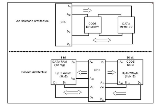
So all the architecture which i covered below they all are belong to Harvard Architecture and RISC processor.
About Attiny 44
The high-performance, low-power Microchip AVR RISC-based CMOS 8-bit microcontroller combines 4KB ISP flash memory, 256-Byte EEPROM, 256B SRAM, 12 general purpose I/O lines, 32 general purpose working registers, an 8-bit timer/counter with two PWM channels, a 16-bit timer/counter with two PWM channels, internal and external interrupts, an 8-channel 10-bit A/D converter, a programmable gain stage (1x, 20x) for 12 differential ADC channel pairs, programmable watchdog timer with internal oscillator, a internal calibrated oscillator, and three software selectable power saving modes. By executing powerful instructions in a single clock cycle, the device achieves throughputs approaching 1 MIPS per MHz, balancing power consumption and processing speed.
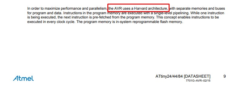
While reading the datasheets of ATtiny 44 i cleard my point whether it is harvard acrchitecture or not?.I found it is a haravard architecture .
Features
- High performance, low power AVR® 8-bit microcontroller
- Advanced RISC architecture
- ● Non-volatile program and data memories
- Peripheral features
- I/O and packages
- Operating voltage:2.7 - 5.5V for Atmel ATtiny24/44/84
- ● Speed grade
Atmel ATtiny24/44/84: 0 - 8MHz at 2.7 - 5.5V, 0 - 16MHz at 4.5 - 5.5V
- Low power consumption Active mode: 1MHz, 2.7V: 800µA Power-down mode: 2.7V: 2.0µA
Pin diagram
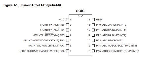
The Atmel® ATtiny24/44/84 is a low-power CMOS 8-bit microcontroller based on the AVR enhanced RISC architecture. By executing powerful instructions in a single clock cycle, the Atmel ATtiny24/44/84 achieves throughputs approaching 1MIPS per MHz allowing the system designer to optimize power consumption versus processing speed.
Block diagram of Attiny 44
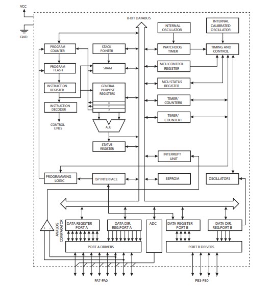
The Atmel® AVR® core combines a rich instruction set with 32 general purpose working registers. All 32 registers are directly connected to the arithmetic logic unit (ALU), allowing two independent registers to be accessed in one single instruction executed in one clock cycle.The resulting architecture is more code efficient while achieving throughputs up to ten times faster than conventional CISC microcontrollers.
Architectural Overview
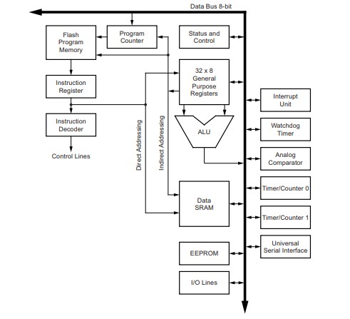
This section discusses the Atmel® AVR® core architecture in general. The main function of the CPU core is to ensure correct program execution. The CPU must, therefore, be able to access memories, perform calculations, control peripherals, and handle interrupts. For more information referred Atmel ATtiny24/44/84 datasheet
Program the ATtiny 44
To program the ATtiny 44 we need to write a program first and to run this code we also need respective envirnoment.Basically we need programming code and its envirnoment to build into a any board.So we can write a code in Arduino programming language or we can write a code in embedded C as well.Also i am going to explore different envirnoment to run different type of program on my Attiny 44 board.So lets begin to write a code and understand the procedure to used platform for it.
Step 1.To write a code in different languages.
Step 2.To run a code on different platform.
In next section we are going to learn differnt way to write a code and used different platform to run these code.
Getting started with Arduino
Introduction:
Arduino is an open-source electronics platform based on easy-to-use hardware and software. Arduino boards are able to read inputs - light on a sensor, a finger on a button, or a Twitter message - and turn it into an output - activating a motor, turning on an LED, publishing something online. You can tell your board what to do by sending a set of instructions to the microcontroller on the board. To do so you use the Arduino programming language (based on Wiring), and the Arduino Software (IDE), based on Processing.
What is the Arduino Software (IDE)?
The Arduino Integrated Development Environment - or Arduino Software (IDE) - contains a text editor for writing code, a message area, a text console, a toolbar with buttons for common functions and a series of menus. It connects to the Arduino and Genuino hardware to upload programs and communicate with them.
Install Arduino
Boards Manager Installation
This core can be installed using the boards manager. The boards manager URL is:
- http://drazzy.com/package_drazzy.com_index.json
1.File -> Preferences, enter the above URL in "Additional Boards Manager URLs"
2.Tools -> Boards -> Boards Manager... *If using 1.6.6, close boards manager and re-open it (see below)
3.Select "ATTinyCore by Spence Konde" and click "Install".
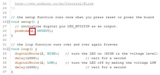
Arduino programming Code

Procedural Steps to run Blinking LED Arduino code:
Step 1.Getting started
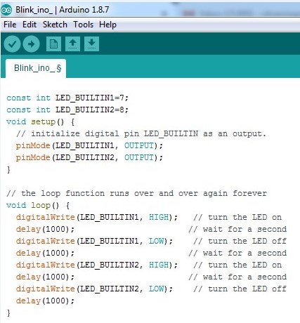
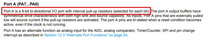
Step 2.Copy the Arduino programming code in editor window and save it.Note:Before using the pins of ATtiny 44 i went through datasheets of it and got to know that pin 7 and 8 is an general purpose, dual function input/output pins which i can used as output pins in my code.
From Datasheets:
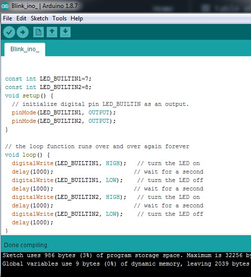
Step 3.Click on verify and done compiling
Step 4.Interfaced ATtiny 44 board with FAB ISP and connect through USB connector to computer.Click on upload.
Step 5.

Embedded C programming Code

Procedural Steps to run Blinking LED C code:
Step 1.Getting started
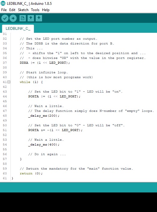
Step 2.Copy the C code in editor window and save it.
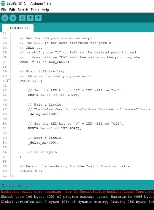
Step 3.Click on verify and done compiling
Step 4.Interfaced ATtiny 44 board with FAB ISP and connect through USB connector to computer.Click on upload.
Step 5.
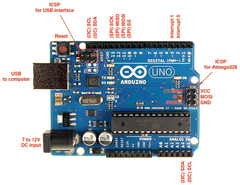
About Arduino Board
Arduino Uno is based on ATmega328P Atmel AVR family microcontroller (MCU). This MCU has 32KB of flash, 2KB of SRAM and 1 KB of EEPROM. It has 14 digital IO pins (PORTD – 8pins, PORTC – 6 pins, PORTB – 5pins), 6 Analogue input pins, which can be sampled using on-chip ADC. It also has 6 PWM outputs multiplexed on to the digital IO pins. A 16 MHz crystal is installed on the board.
Features of Arduino Uno Board
- 1.The operating voltage is 5V.
- 2.The recommended input voltage will range from 7v to 12V.
- 3.The input voltage ranges from 6v to 20V.
- 4.Digital input/output pins are 14.
- 5.Analog i/p pins are 6.
- 6.DC Current for each input/output pin is 40 mA.
- 7.DC Current for 3.3V Pin is 50 mA.
- 8.Flash Memory is 32 KB.
Let's learn how to read a pushbutton using Arduino's digital input! We'll connect up a simple circuit using a solderless breadboard and use some simple Arduino code to control a single LED.
Hardware Build
As you can see on breadboard there are pushbutton, LED, two resistors, and wires connected to the Arduino.Connect breadboard VCC and ground to Arduino 5V and ground (GND) pin.From above image the idea about circuit connection is got cleard.
Program in Arduino
Test the code
About ESP -32
I never used this family of microcontroller so i am very much excited to learn and get to know the installation procedure,Pins diagrams and compiling and uploading code as well.Also want to know how this family of microcontrooler is different than others.
The ESP-WROOM-32 which is a 32-bit microprocessor.ESP32 is a series of low-cost, low-power system on a chip microcontrollers with integrated Wi-Fi and dual-mode Bluetooth. ... ESP32 is created and developed by Espressif Systems, a Shanghai-based Chinese company, and is manufactured by TSMC using their 40 nm process. It is a successor to the ESP8266 microcontroller.
Pin configuration
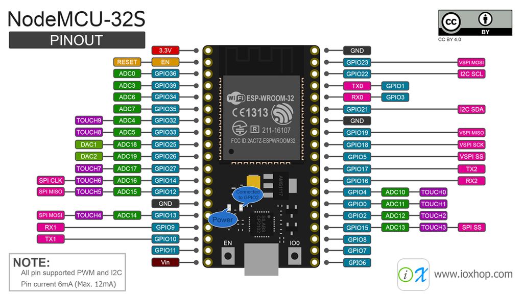
In this article, we will talk about the internal details and the pinning of ESP32.One imporatant thing about ESP -32 is that it is having 34 general purpose I/O pins.Also some of the pins works as a ADC (12-bit).ESP-32 have on board touch sensors,Bluetooth and wi fi module as well.Read more about pin diagram.
Thing we required
Environment Arduino IDE
Programming ESP-32
Testing the board

Step 1.Select the board ESP 32 Dev Module
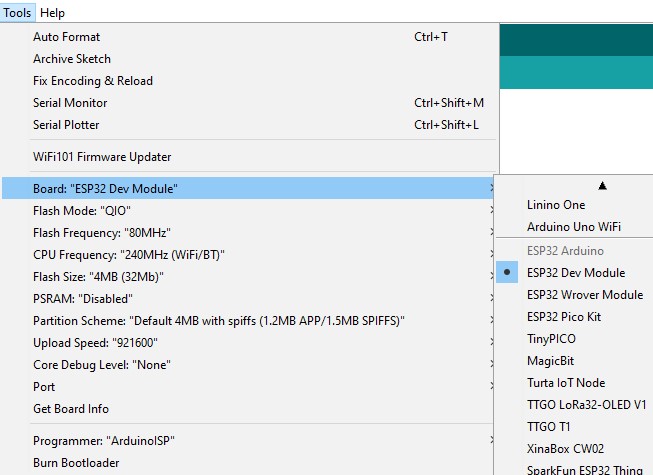
Step 2.Do not change other parameters keep them as it is!
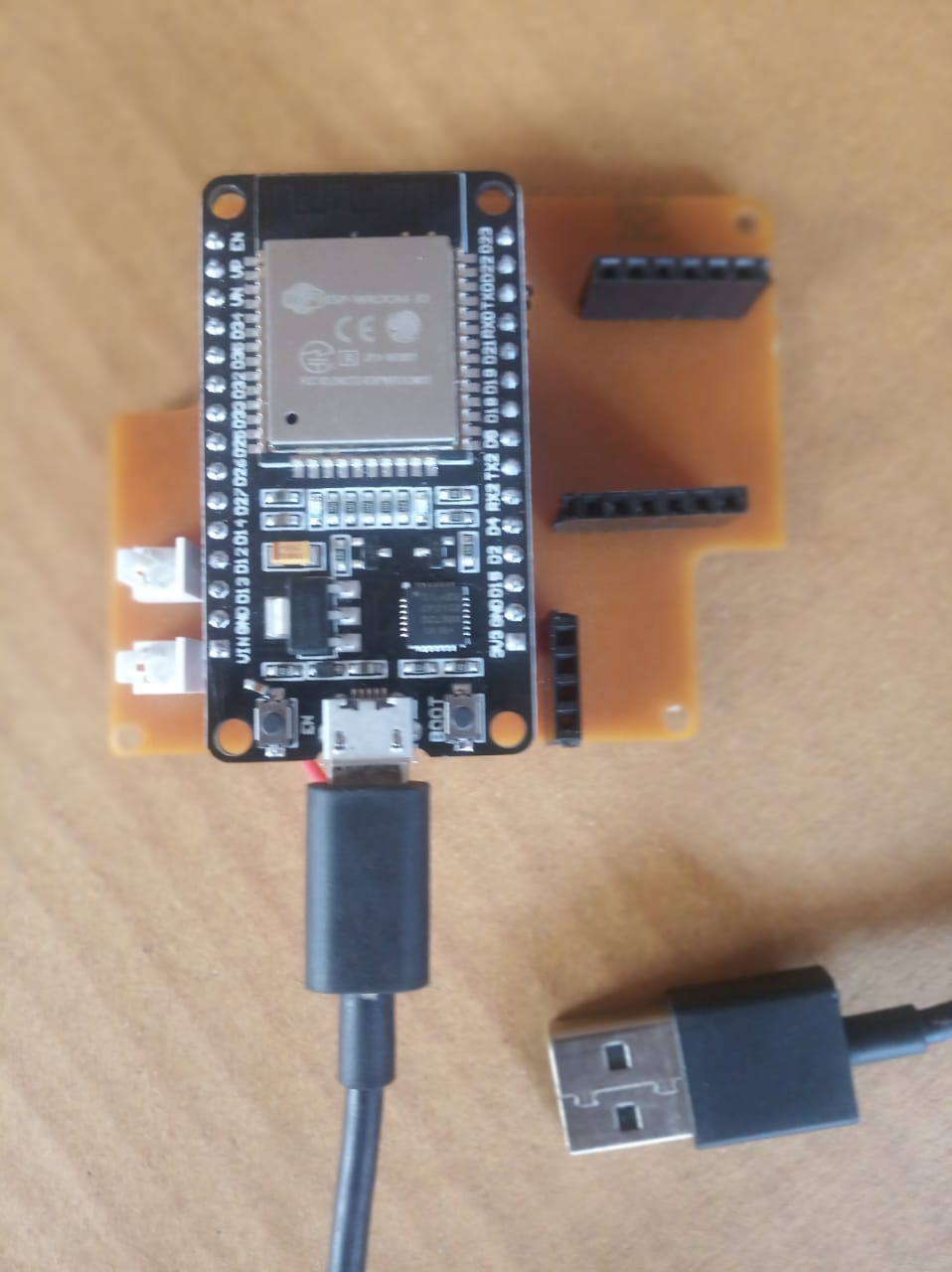
Step 3.Use USB programming cable to power up the board and connect it to laptop.
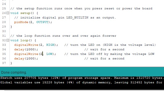
Step 4.After finishing above compile your code
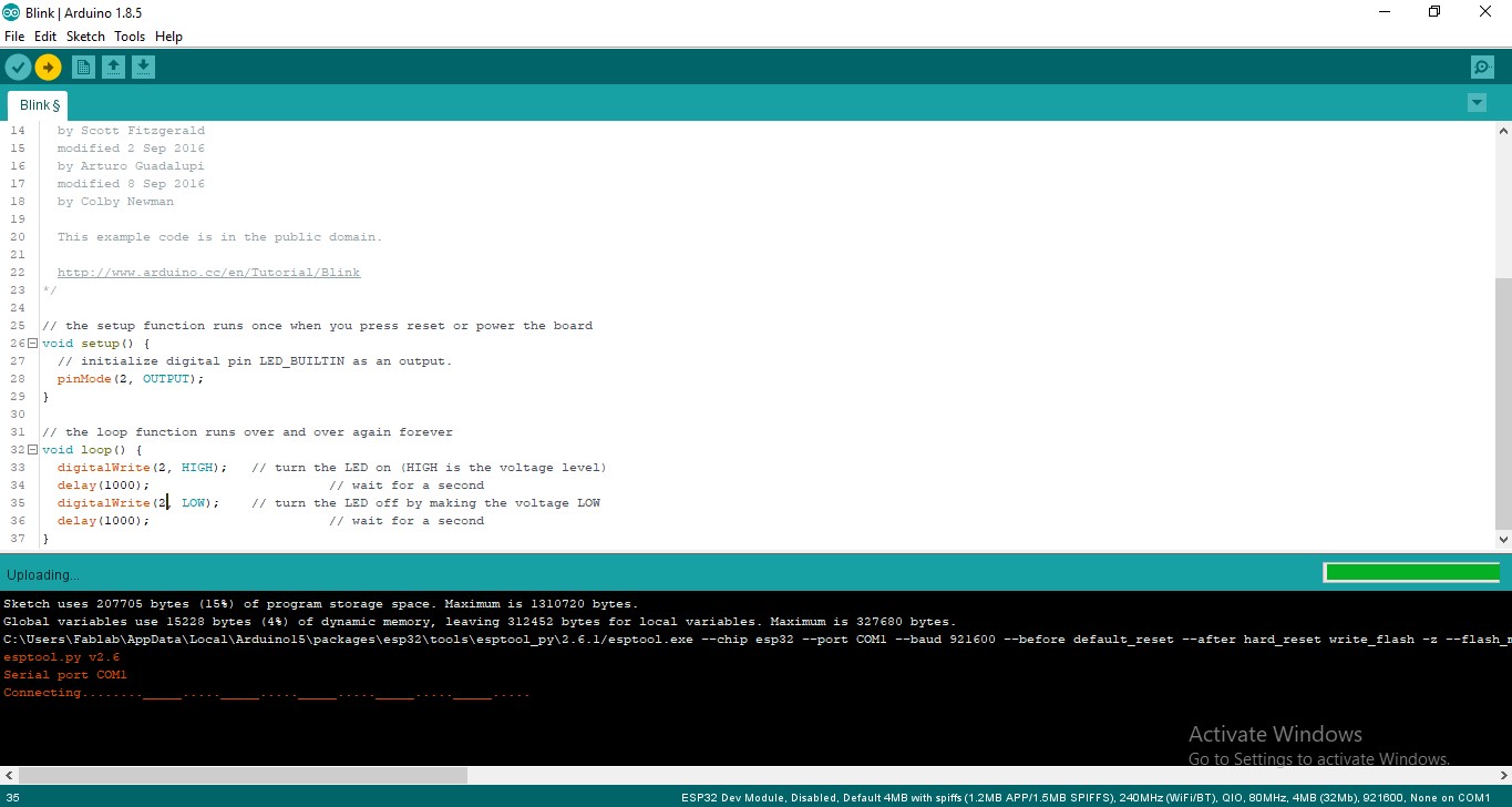
Step 5.Finally upload the program in ESP 32 board.
Struggled with errors:
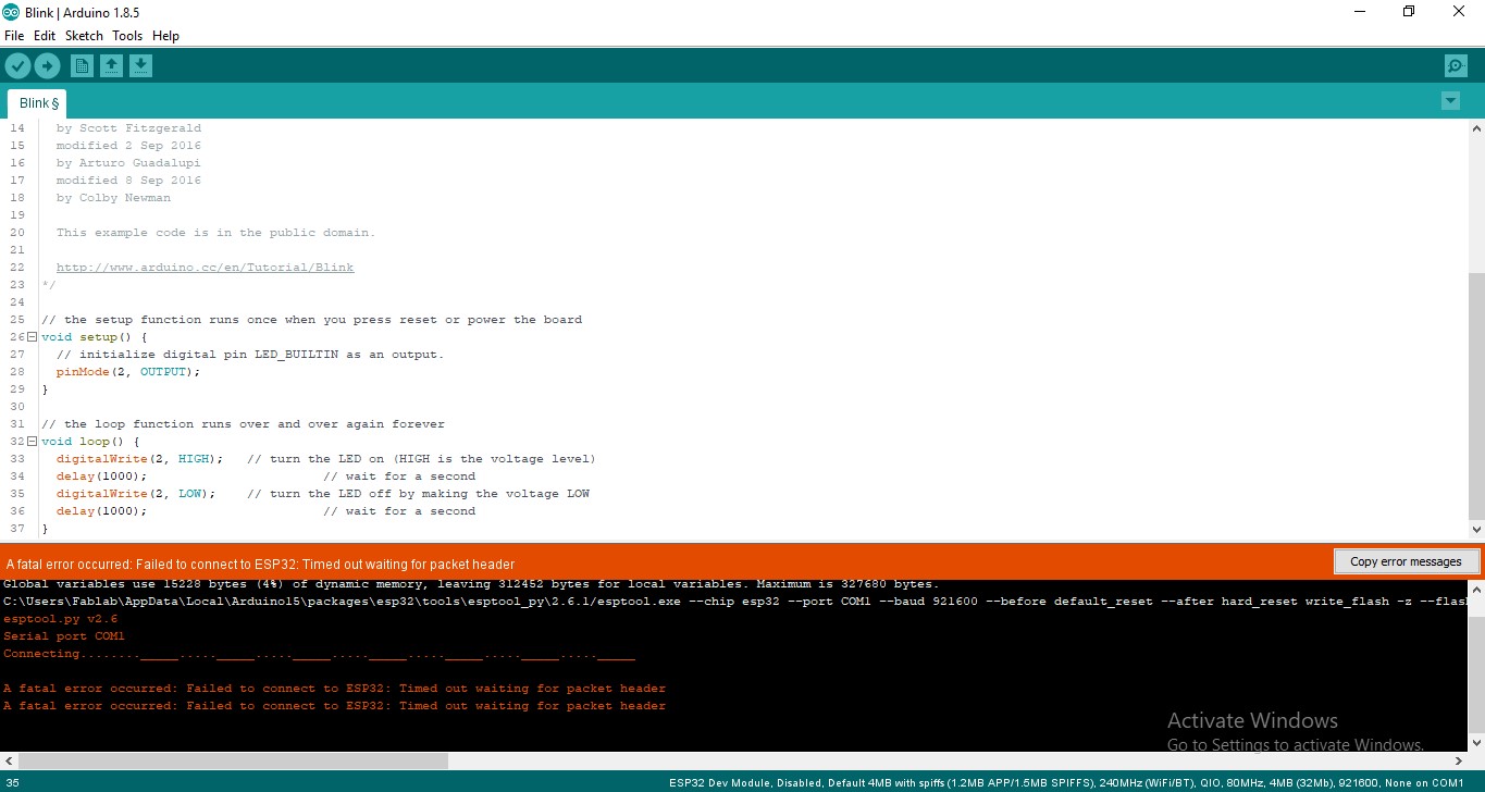
Step 6.Errors i got ....To be continue

>when i start uploading my code i got this error i.e.Failed to connect to ESP32: Timed out waiting for packet.The reason to get this kind of error is that when we are uploading new code into ESP -32 ,ESP -32 is running the older code and it doesnt accept the newer one so we need to tell the ESP-32 that to upload this new one for that we need to hold boot button just for 2 sec and leave it,.Here timing of push boot button is important.When you see like this conneting... at that instant only you have to press boot button for 2-3 sec and leave it.
Group assignments
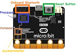
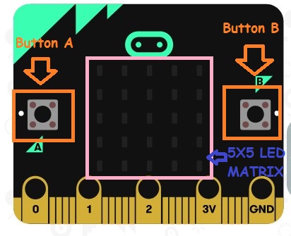
Micro:bit
Micro:bit is a pocket-sized microcontroller designed for kids and beginners learning how to program, letting them easily bring ideas into DIY digital games, interactive projects and robotics. micro:bit comes with a variety of on-board modules, including a 5x5 LED matrix (also supports light detection), 2 programmable buttons, motion detector, Compass and Bluetooth® Smart module. Additionally, you may attach more modules such as a servo motor, RGB LED lights through 5 I/O rings or 20 edge connectors.
MakeCode and micro:bit
An Introduction to MakeCode
MakeCode for micro: bit is one of the most widely used graphical programming environment from the micro: bit website. It is an open source project developed by Microsoft.
How to Use micro:bit
As i am new to microbit platform i start with online programming platform - The Makecode editor.
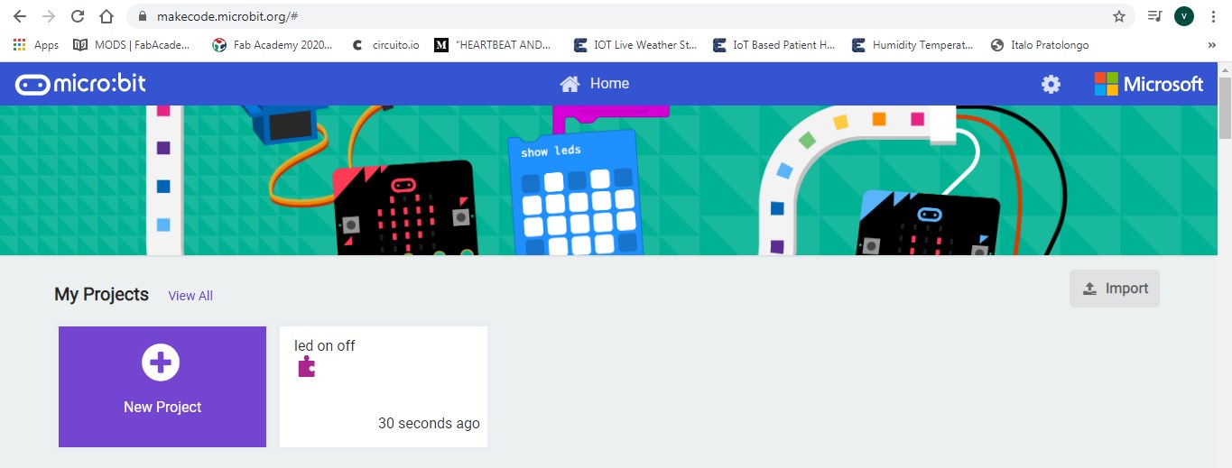
Step 1:Open Make Code
Step 2:Connect Micro bit to computer
Connect Micro bit to computer through USB cable.Once it get connected power light will on
Step 3:Click on New Project
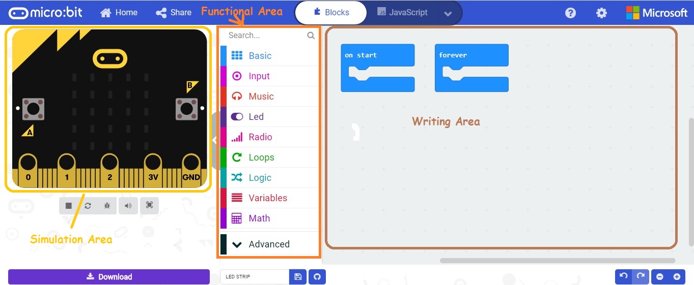
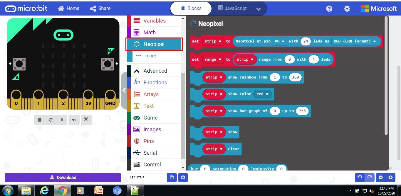
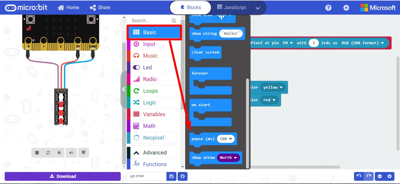
Micro:bit window is classified into Simulation window, Functional Area and Writing Area
Simulation window:simulates the operating status of micro: bit. During the process of programming,
you can always check how your program looks like the through this window
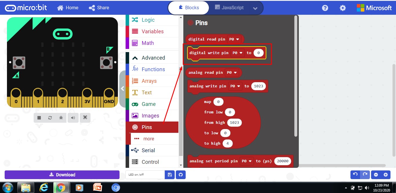
Functional window:In this block different function are vailable like input,logic,loop and output etc
Writing area:In this section we can write eithet block code or javascript code
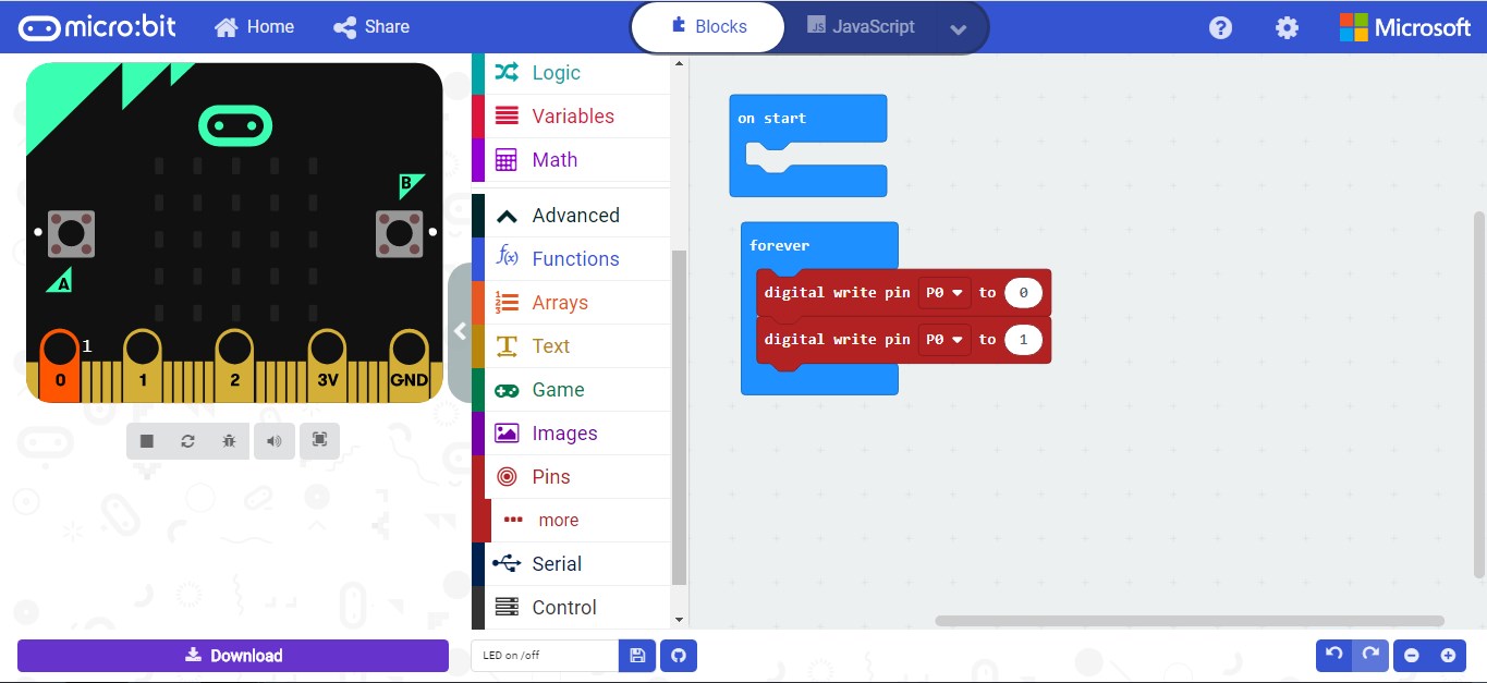
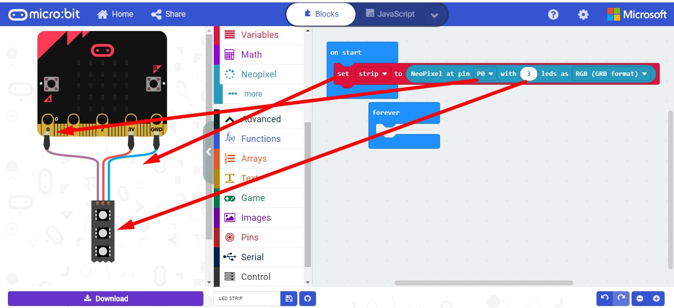
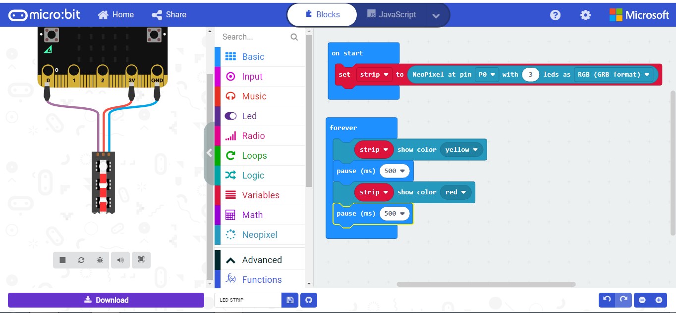
Step 4:Start Writing the code
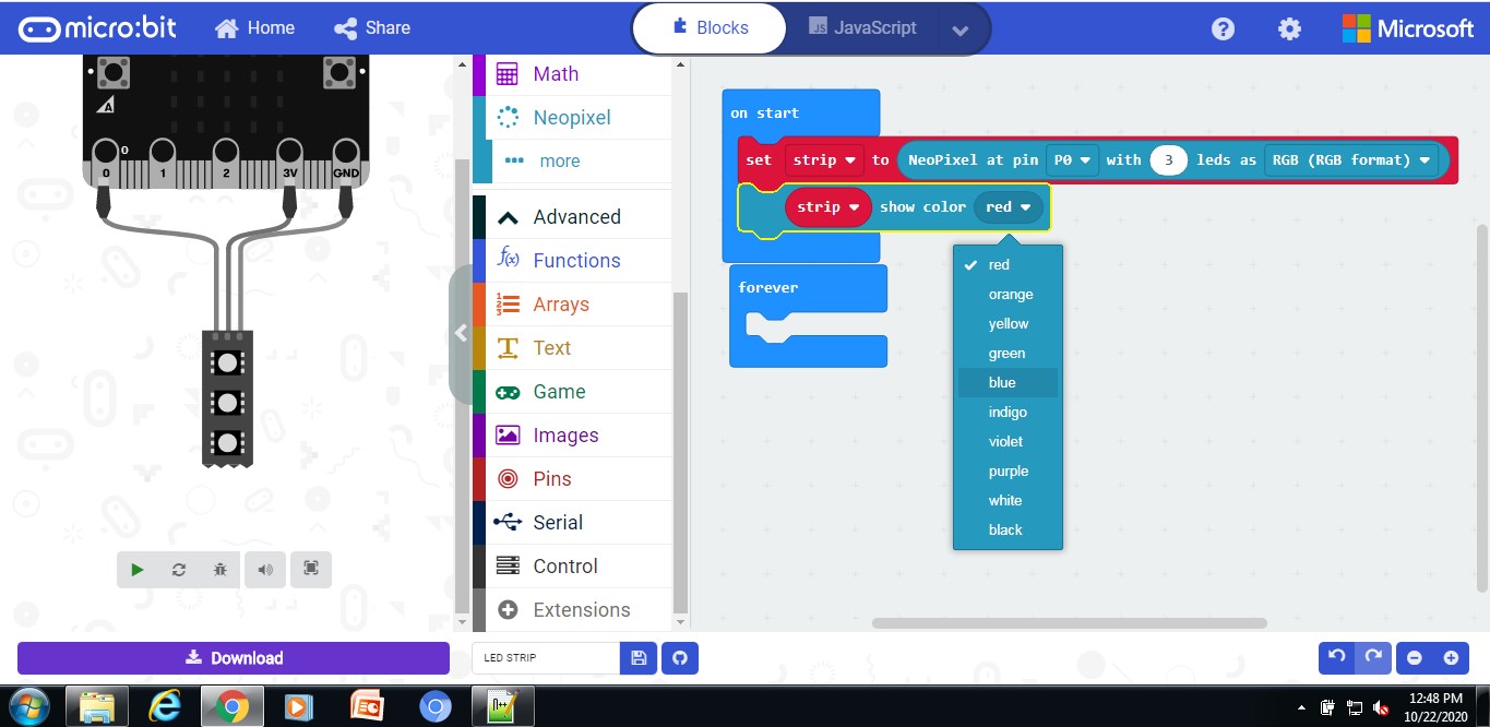
Example 1:
Note:Shwon Software simulation only since not having Lab Access due to covid 19.
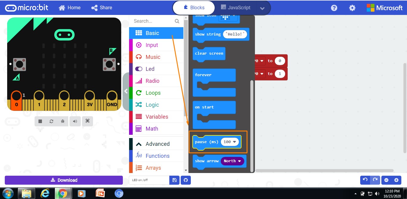
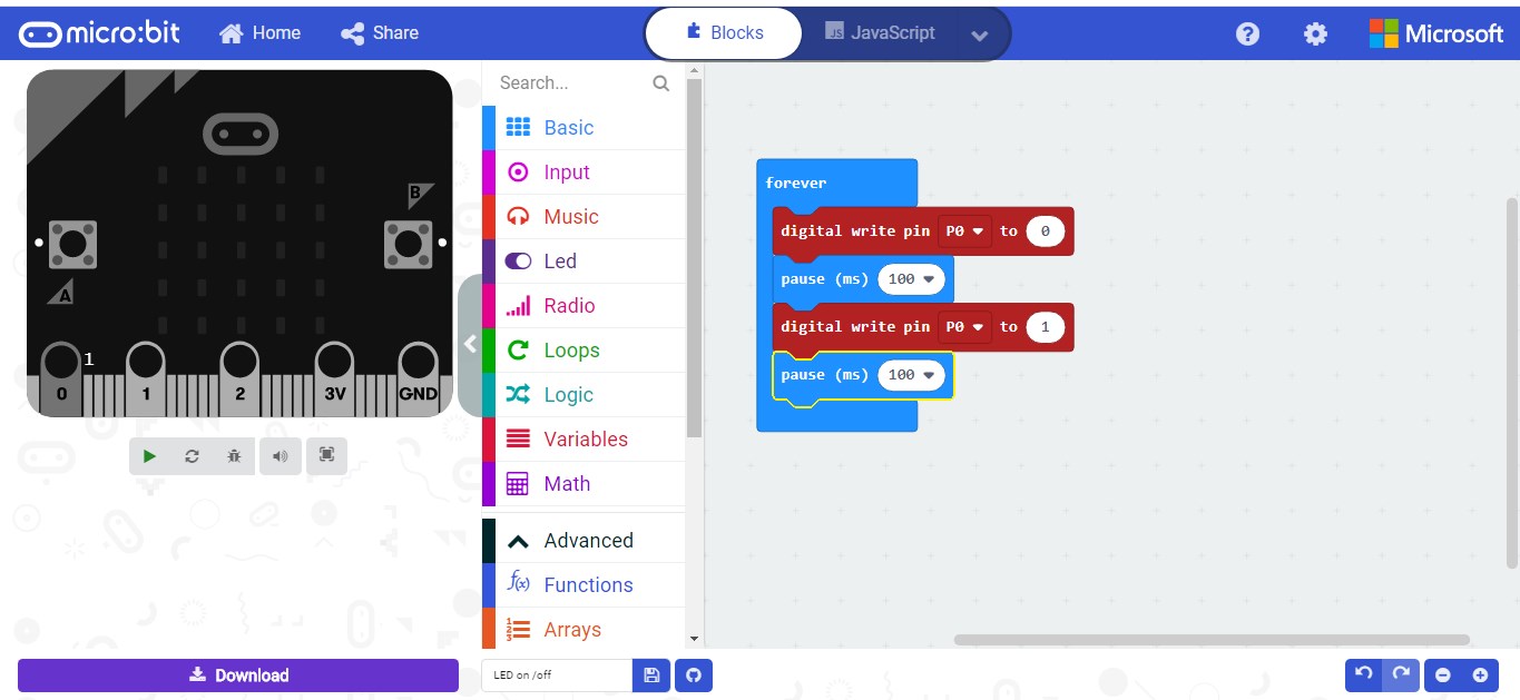
Example 2:
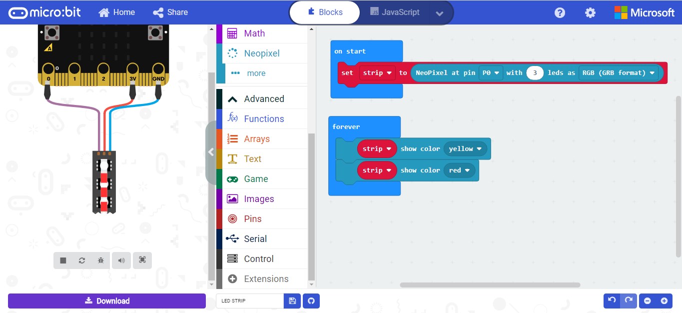
Step 5:Download the code and HEX file will be generated
Step 6:Move the hex files and drag it to microbit drive
For more details please click here