8. Embedded Programming
This week, I learned a programming with Arduino IDE and C language and experienced the programming with Arduino IDE that LED is turned on and off with a switch button. And also, to understand how the microcontroller: ATTiny44 works, I read its datasheet partially.
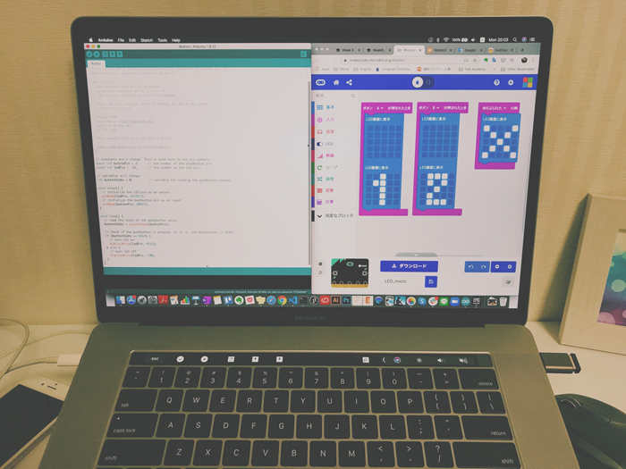
For group assignment, I tried running micro:bit and controlling its LEDs with some directions.
Assignments
group assignment:
- Compare the performance and development workflows for other architectures.
individual assignment:
- Read a microcontroller data sheet.
- Program your board to do something, with as many different programming languages and programming environments as possible.
X. Group Assignment
Link to group session page.
X. Individual Assignment
1. Read a datasheet
I checked with the ATTiny44’s datasheet.
Features
-
Advanced RISC Architecture
32 x 8 General Purpose Working Registers -
Memory
2K/4K/8K Bytes of In-System, Self-programmable Flash Program Memory
128/256/512 Bytes of In-System Programmable EEPROM 128/256/512 Bytes of Internal SRAM -
Peripheral Features
One 8-bit and One 16-bit Timer/Counter with Two PWM Channels, Each
Programmable Watchdog Timer with Separate On-chip Oscillator
Universal Serial Interface -
I/O and Packages
Available in 20-pin QFN/MLF/VQFN, 14-pin SOIC, 14-pin PDIP and 15-ball UFBGA
Twelve Programmable I/O Lines -
Operating Voltage
1.8 - 5.5 V- 0 – 4 MHz @ 1.8 – 5.5V
- 0 – 10 MHz @ 2.7 – 5.5V
- 0 – 20 MHz @ 4.5 – 5.5V
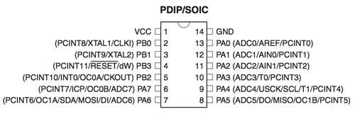
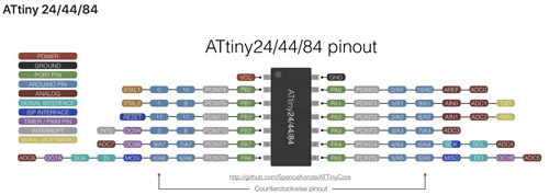
Pinout of ATtiny44A
Mainly, Vcc, GND, and I/O ports (Ports A, Ports B(RESET pin is PB3 pin for ATtiny44)).
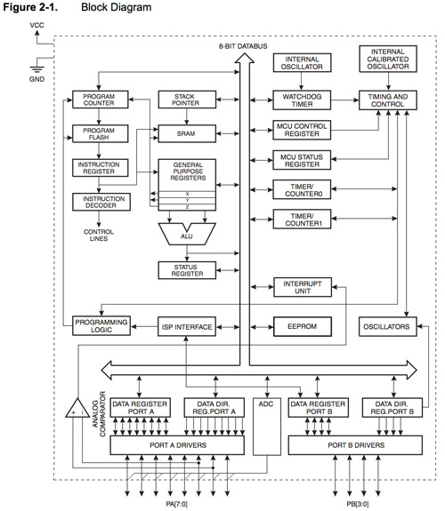
Overview
Block Diagram shows the architecture of the microcontroller, how each element like register and Arithmetic Logic Unit (ALU) communicates with each other. So that’s very important information for understanding how the microcontroller works.
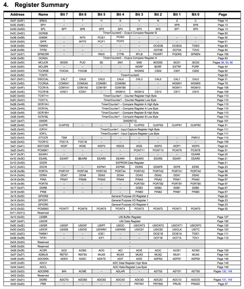
Register
I’d like to use C in the future(not this week), so I need to understand register.
So here is the excerpt from Wikipedia.
-
A register is a quickly accessible location available to a computer’s CPU.
-
Processor registers are normally at the top of the memory hierarchy, and provide the fastest way to access data.
-
Almost all computers, whether load/store architecture or not, load data from a larger memory into registers where it is used for arithmetic operations and is manipulated or tested by machine instructions. Manipulated data is then often stored back to main memory, either by the same instruction or by a subsequent one.
It seems that registers cannot stored so large data but small data like for arithmetic operations… There are a lot types of registers and they can be separated into General Purpose I/O register and Certain register.
Uh…I could understand a little bit what the register is but can’t understand how the register works and how to use register. So next step, I’d like to understand them!!
2. Programming with Arduino IDE
Materials
- Programming code: .ino file
Tools
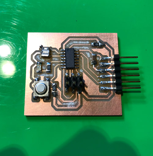
- Circuit board with microcontroller (Echo Hello world board (EHWB))
- Writer (FabISP)
- Arduino IDE
- FDTI connector
- USB connector
- ISP connector
Set up to develop ATtiny tips with Arduino IDE
I used Echo Hello Board made at Week06.
Let’s check its pin position:
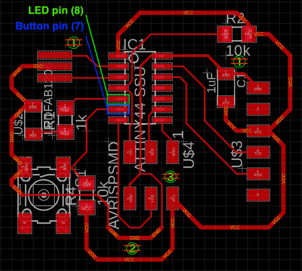
Please note that the described Pin numbers are not physical pin numbers but Arduino Pin’s numbers.
Failure
Correspond pin number of ATtiny with Arduino
According to this page, when you’d like to develop ATtiny with Arduino IDE, you need to input Arduino’s pin numbers corresponding to ATtiny44’s pin in the code.
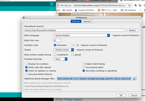
To write a program to ATtiny44 on the circuit board with Arduino IDE, some setup is needed. Reference page is here.
Copied URL: https://raw.githubusercontent.com/damellis/attiny/ide-1.6.x-boards-manager/package_damellis_attiny_index.json.
And then, opened Arduino IDE and moved to Toolbar: Arduino -> Preference and pasted the copied URL to Additional Boards Manager URL and clicked OK.
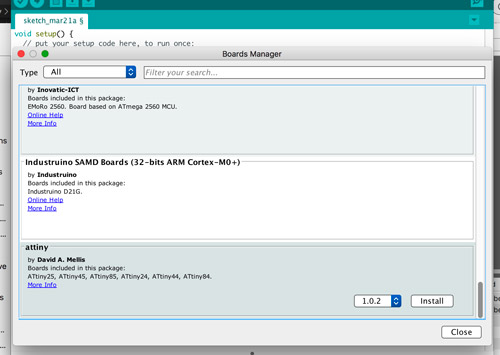
Moved to Toolbar: Tools -> Board -> Boards Manager and installed attiny with the latest version. Make sure to include the microcontroller you’d like to use in description.
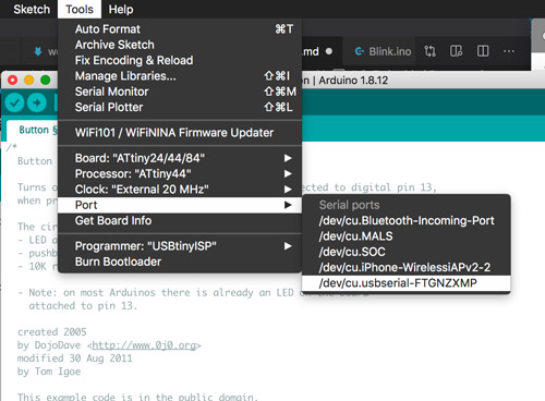
Moved to Toolbar: Tools and set up to Board: ATtiny24/44/84, Processor: ATtiny44, Clock: External 20 MHz, Programer: USBtiny.
All setup has finished!
Programming
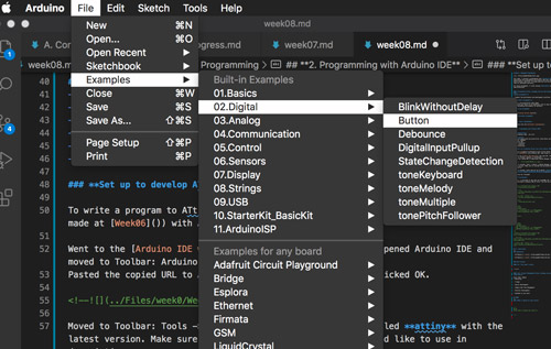
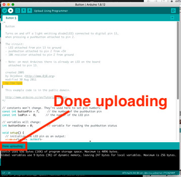
Firstly, I confirmed if the code can be executed properly with a sample code provided in Arduino IDE at first. I used the sample code: Button from Toolbar: File -> Examples -> 02.Digital -> Button.
Connected EHWB and FabISP to my PC (Refer to my week6 page about how to connect those circuits.) Make sure that you selected the port: /dev/cu.usbserial-FTGNZXMP.
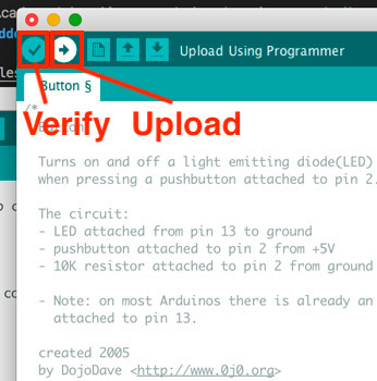
And then click Verify and Upload at Arduino IDE.
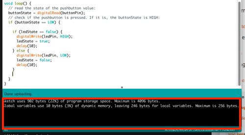
If the message “Done uploading” is shown, writing the code to EHWB is succeed.
Tip
Get the whole capacity of your code
As verifying or uploading your code on Arduino IDE, you can see the whole capacity of your code at the comment space. That’s important for selecting the microcontroller suitable for your tasks.
Code.1 Turn on as left a switch button and Turn off LED while pushing a switch button
const int buttonPin = 7;
const int ledPin =  8;

int buttonState = 0;
int a = 100;
boolean ledState = false;

void setup() {
  pinMode(ledPin, OUTPUT);
  pinMode(buttonPin, INPUT);
}

void loop() {
    buttonState = digitalRead(buttonPin);
    if (buttonState == LOW) {
        if (ledState = false) {
        digitalWrite(ledPin, HIGH);
        delay(a);
        ledState = true;
        } else {
            digitalWrite(ledPin, LOW);
            delay(a);
            ledState = false;
        }
    } else {
        digitalWrite(ledPin, LOW);
    }
}
Code.2 Switch turn on and off LED as pushing a switch button
const int buttonPin = 7;
const int ledPin =  8;

int buttonState = 0;
int a = 100;
boolean ledState = false;

void setup() {
  pinMode(ledPin, OUTPUT);
  pinMode(buttonPin, INPUT);
}

void loop() {
    buttonState = digitalRead(buttonPin);
    if (buttonState == LOW) {
        if (ledState == false) {
        digitalWrite(ledPin, HIGH);
        delay(a);
        ledState = true;
        } else {
            digitalWrite(ledPin, LOW);
            delay(a);
            ledState == false;
        }
    } else {
        digitalWrite(ledPin, LOW);
    }
}
Code.3 Blink LED while pushing a switch button
const int buttonPin = 7;
const int ledPin =  8;

int buttonState = 0;
int a = 100;

void setup() {
  pinMode(ledPin, OUTPUT);
  pinMode(buttonPin, INPUT);
}

void loop() {
    buttonState = digitalRead(buttonPin);
    if (buttonState == LOW) {
        digitalWrite(ledPin, HIGH);
        delay(a);
        digitalWrite(ledPin, LOW);
        delay(a);
    } else {
        digitalWrite(ledPin, LOW);
    }
}
2020/11/9 Demonstration - 3 times blinks with push a button
Pablo-san who is my global evaluator gives me a new task to see if I improved my programming skill. The task is ‘Can you add the code to make the led blink three times when you push the button?’. So I revised code.2 and tried running it.
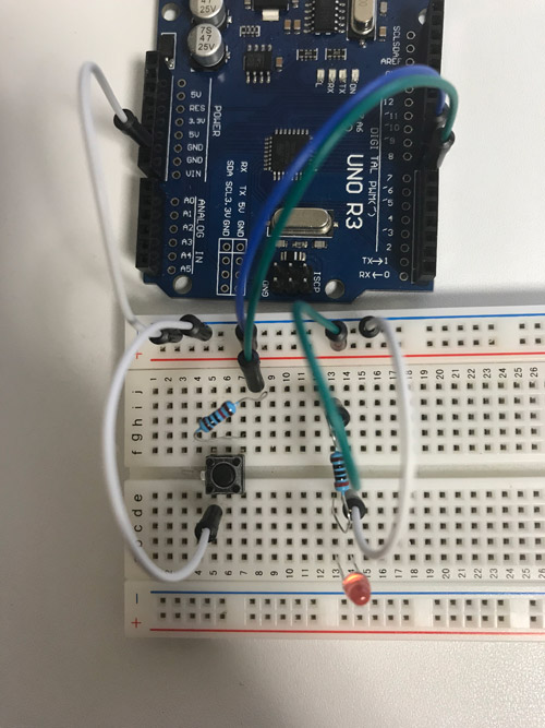
Actually, I lost a writer to write a program to ATtiny44… So I demonstrate it by using Arduino UNO and an breadboard.
The wiring is simple. The 8 pin was used to blight a RED LED (inserted 330Ω resistor). The 7 pin was used to judge if the switch button was pushed (inserted 10kΩ resistor to pull-up 8pin).
Code.4 3 time blinks with push a button
const int buttonPin = 7;
const int ledPin =  8;

int buttonState = 0;
int a = 1000;

void setup() {
  pinMode(ledPin, OUTPUT);
  pinMode(buttonPin, INPUT);
  digitalWrite(buttonPin, HIGH);
  digitalWrite(ledPin, LOW);
}

void loop() {
    buttonState = digitalRead(buttonPin);
    if (buttonState == LOW) {
      for (int i=0; i<=2; i++){
        digitalWrite(ledPin, HIGH);
        delay(a);
        digitalWrite(ledPin, LOW);
        delay(a);
      }
    }else{
      digitalWrite(ledPin, LOW);
    }
}
X. Conclusions
Submission
(Code.1 is the sample code in Arduino IDE.)
Self-reviews
1. This week’s work
This is my first time to try C language. But C was very very difficult for me. I felt like I don’t have enough experience with a programming. My instructor said to me that you should use Arduino IDE alternatively and get used to it. So this week I learned Arduino IDE first.
But I also heard that C is one of the most classical and famous languages and used in many kinds of systems or apps. So I’d like to learn C someday.(but not now…)
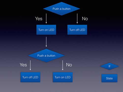
Logic Diagram
When I was struggling with writing code 2, Kai Naito who is one of the instructors in Kamakura told me Logic Diagram (Thank you.) As I decomposed my tasks to its elements and showed them as Logic Diagram, my thought became clear and I could solve my task. It’s definitely powerful technique for me to create my own code.
2. Project Management
Score (Max: 100)
-
Hierarchy: None
-
Triage: None
-
Spiral Development: 100
My instructor gave me the questions about LED blinking and I solved them with th e programming. -
Supply-side Time Management: 0
I totally forgot the time management though I could finished by limit time of the session. -
Parallel Development: 100
I printed some parts for my Final Project in parallel to the local session this week. -
Document as you work: 60
MEMO
What I wanted to learn more
-
C language
-
Microcontroller
Type, Difference, Principle (How does the microcontroller works?). -
Fuse
Saverio who is the instructor in Asia Review suggests you should learn about Fuses and how to use them to activate different functions in your microcontroller (Thank you for instructing us.). So here is the hint page of what fuse is.
- Make file
Saverio also told us about Male file and recommended this page to learn make file.