10. Input Devices
  individual assignment:
      measure something: add a sensor to a microcontroller board
      that you have designed and read it
   group assignment:
      probe an input device's analog levels and digital signals
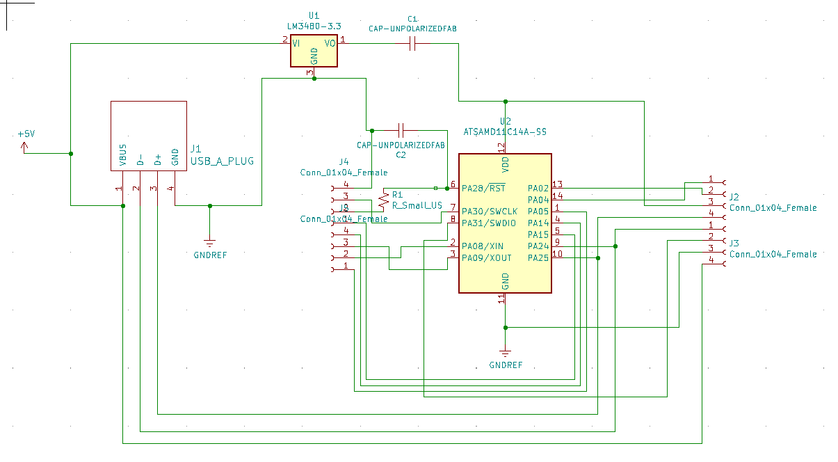
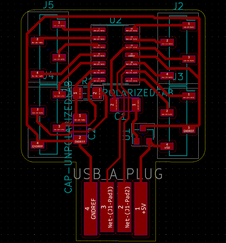
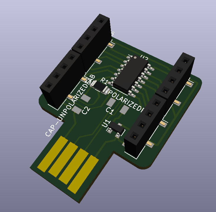
I’ve designed a multi purpose board with a SAMD11C
But for this week, due to coronavirus, I can’t mill my own board, so I will use an Arduino Uno and a 37-in-1 sensor kit.
Using some sensors
I start to work on my final project, so I made a little reverse engineering.
The litter robot inputs are :
- 3 buttons
- a cat sensor (apparently a load sensor by reading the manual but surprise)
- a anti pinch line
- hall sensor (I found it by unmount the base of the litter and reading patents, ex: US6463881B2), globe contains magnets inside plastic.
Buttons are classical switches.
Load sensor is a switch activated by a spring-loaded leg.
Anti pinch system is another switch activated by a line with a metal plate acting as a spring.
Hall sensor part is two hall sensor mounted on opposite side and act bi-polar Hall sensor.
For detecting magnets, I have 2 solutions:
- hall sensor
- reed switch
My bench
I use an Arduino and I wrote a generic code to test analog and digital sensors.
/*****************************
* Generic sensor bench for arduino
*
* @author Florent Lemaire
*
*****************************/
int Led = 13 ; // define LED Interface
int digitalPin = 3; // define the digital sensor interface
int analogPin = A3; // define the analog sensor interface
int valDigital ; // define numeric variable
int valAnalog ;// define analogic variable
FILE serial_stdout;//for quicker stdout instead of many serial.print and println
// Function that printf and related will use to print
int serial_putchar(char c, FILE* f) {
if (c == '\n') serial_putchar('\r', f);
return Serial.write(c) == 1? 0 : 1;
}
void setup ()
{
Serial.begin(9600); // initialize serial communication at 9600 bits per second:
pinMode (Led, OUTPUT) ; // define LED as output interface
pinMode (digitalPin, INPUT) ; // define input for digital
pinMode (analogPin, INPUT) ; // define input for analog
// Set up stdout
fdev_setup_stream(&serial_stdout, serial_putchar, NULL, _FDEV_SETUP_WRITE);
stdout = &serial_stdout;
}
void loop ()
{
delay(20);
valDigital = digitalRead(digitalPin); // digital
valAnalog = analogRead(analogPin); // analog
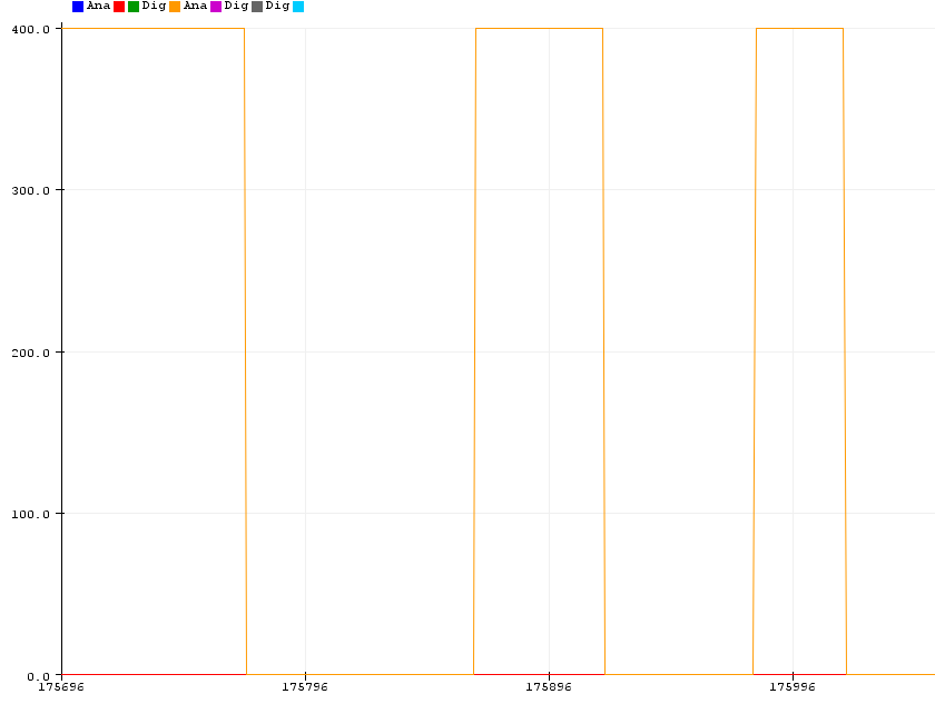
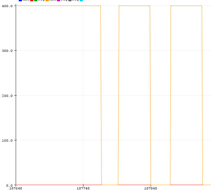
printf("Ana: %i Dig: %i \n", valAnalog, valDigital*400); //serial output in only one line :)
if (valDigital == HIGH) // onboard visual indicator
{
digitalWrite (Led, HIGH);
}
else
{
digitalWrite (Led, LOW);
}
}
And here my generic wiring I will use for most of the sensors :
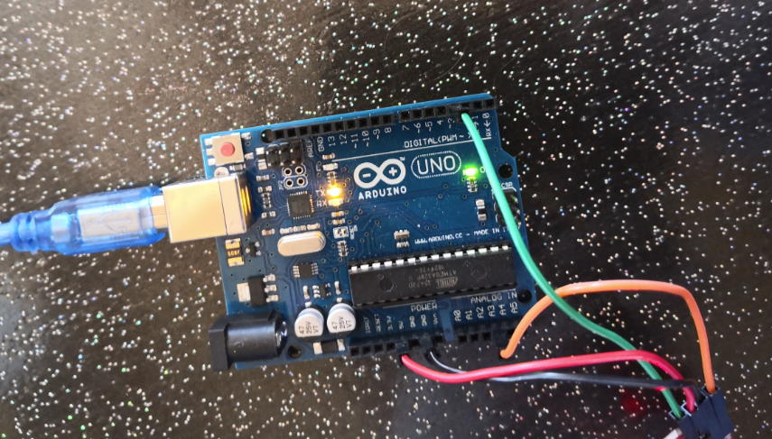
- Red on +5v
- Black on GND
- Green on PIN 3 for Digital Input
- Orange on PIN A3 for Analog Input
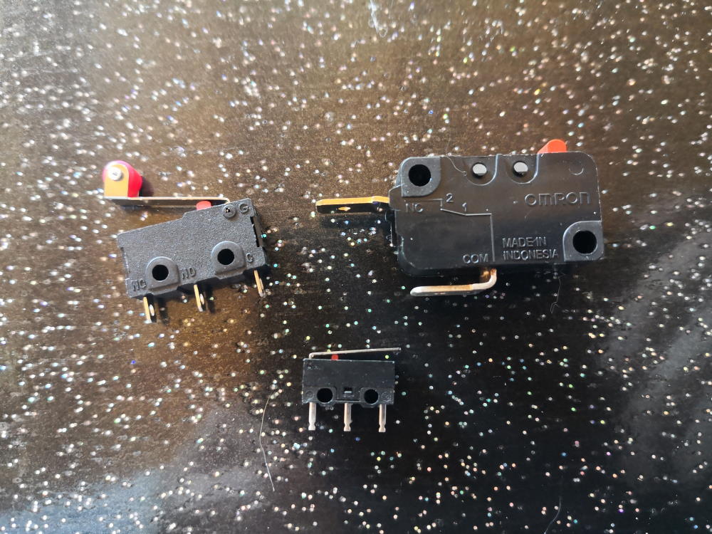
Microswitch
These are commonly used in 3D printer as endstop. They exist in 2 pins or 3 pins model.
In 3 pins models, the pins are:
- COM
- NO : Normally Open
- NC : Normally Closed
Regardless of the type the basic way of working is the same, when you press it:
- A typically 5 Volt signal (High) drops to 0 Volt (Low): Normally closed (NC) switch
- A 0 Volt signal (Low) rises to 5 Volts (High): Normally open (NO) switch
If you choose a 2 pins switch, you have to be careful and verify if you have a NC or NO. If you have a 3 pins switch, you can use in the 2 way depends on how you plug (always plug input C and choose between NC or NO, you also plug 2 outputs and make routing. If you plug only NC and NO, it will do nothing because they are no wired together).
Wiring :
- C to RED (+5v)
- NO to GREEN (digital)
Tip : to clean input signal, I also add a led from NO to GND to remove residual current and clean signal. I also add a wire from A3 to GND to clean analog input and remove noise (no need to change code).
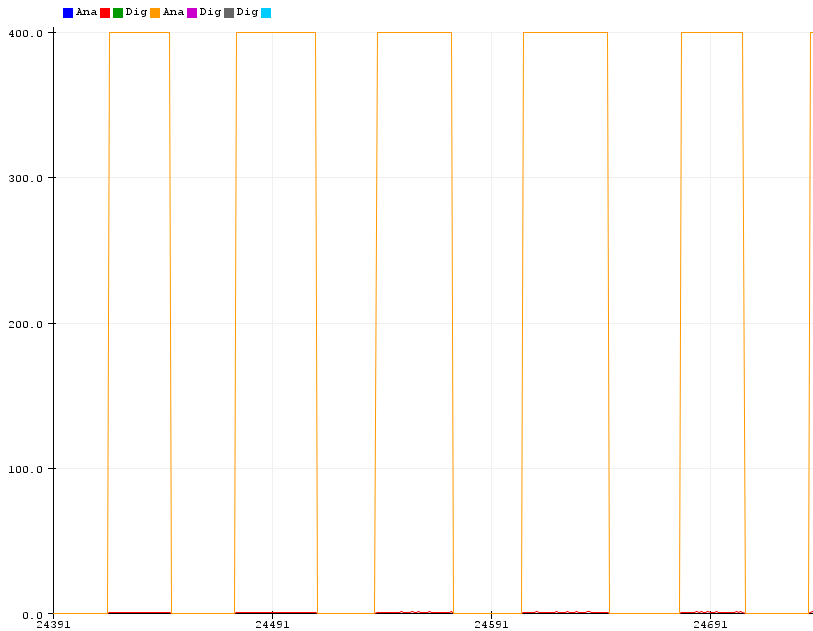
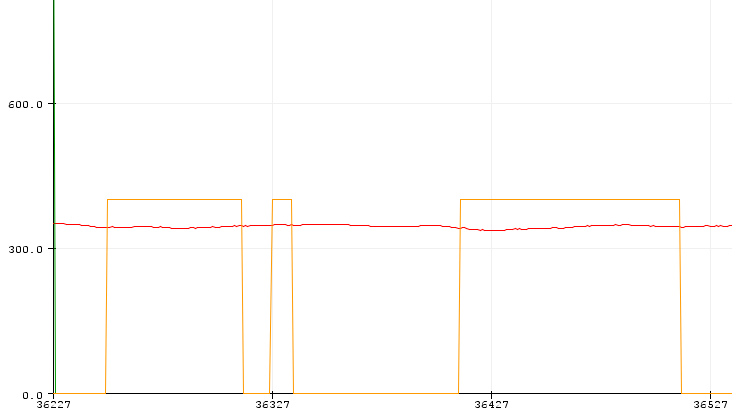
It’s HIGH when I press switch, LOW when not.
Logic is inverted when wiring to NC, LOW when pressed, HIGH when not.
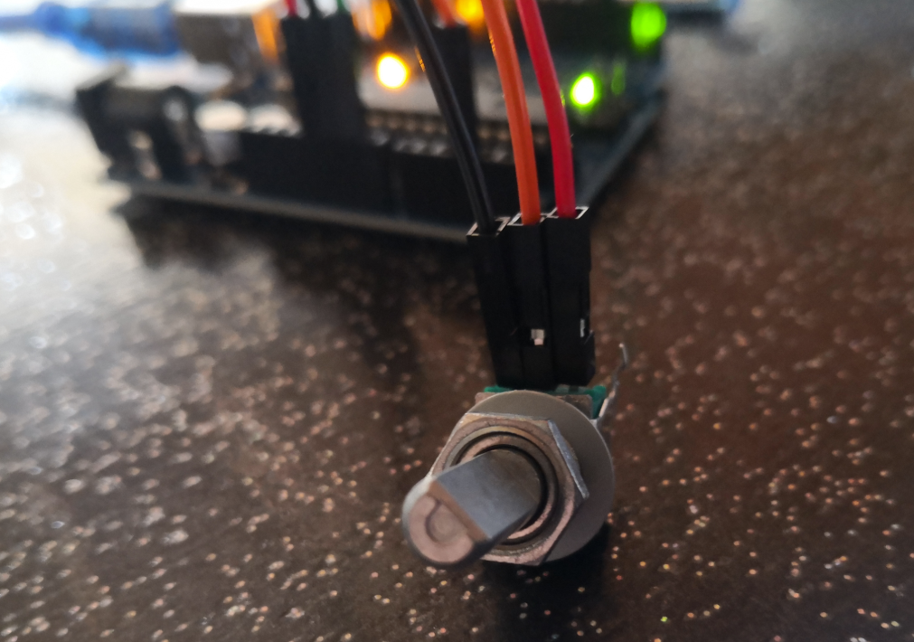
Button
It works like an NO switch. First, because my button have 4 pins, I have to find the correct pair with a multimeter.
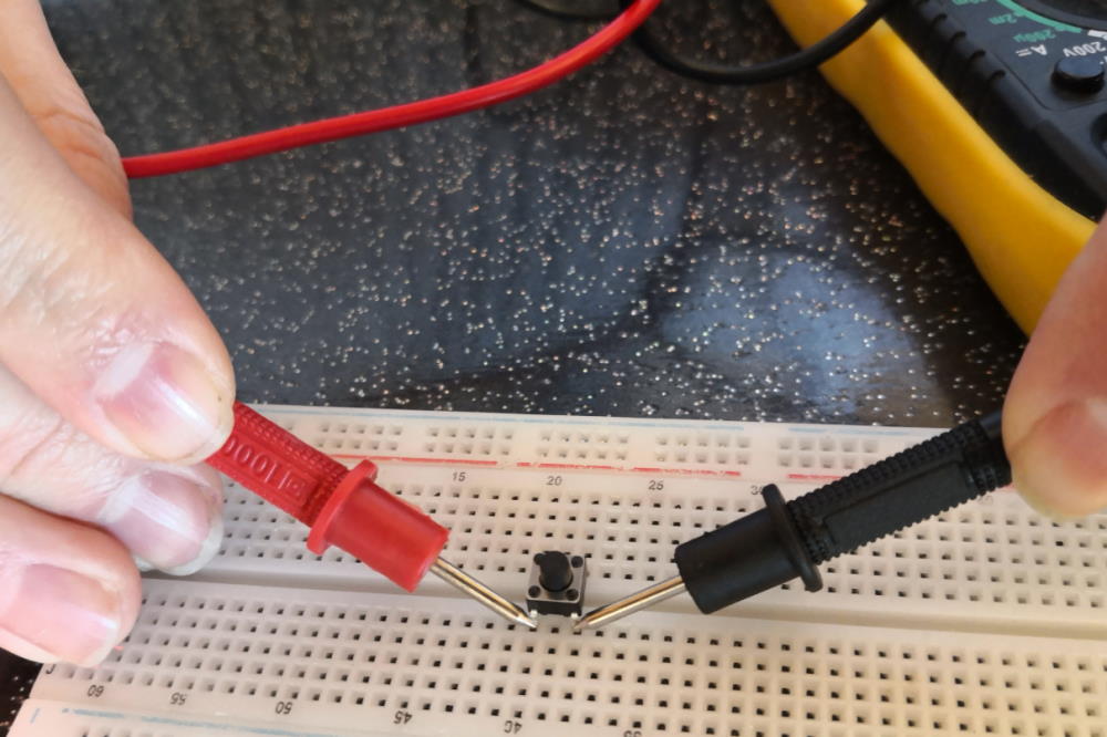
Then I plug a pin to +5v (red) and the other to pin 3 (green).
When I press button, it goes HIGH. It’s LOW when button is not pressed.
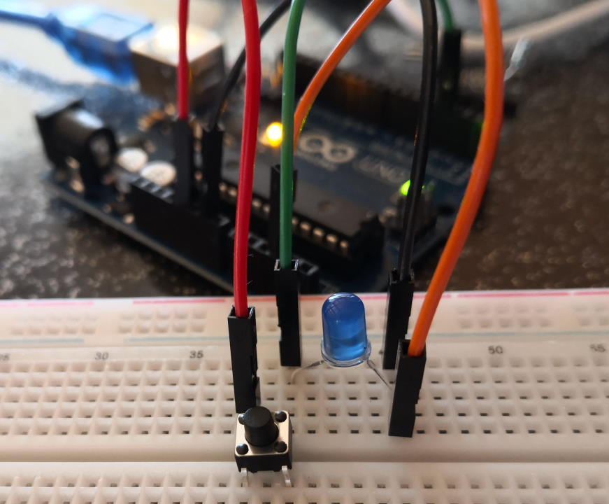
Tip : like switch, to clean input signal, I also add a led from button to GND to remove residual current and clean signal. I also add a wire from A3 to GND to clean analog input and remove noise (no need to change code).
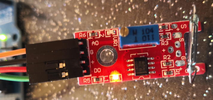
Hall sensor
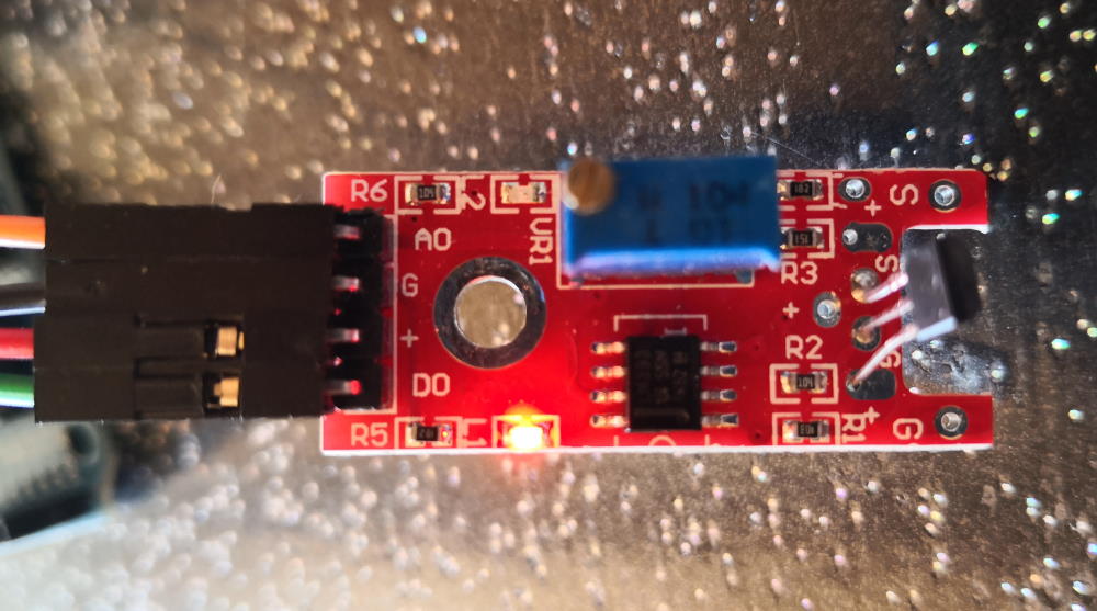
With this sensor I can have at the same time analog and digital values, so I plug :
- A0 to ORANGE (analog)
- G to BLACK (gnd)
- (+) to RED (+5v)
- D0 to GREEN (digital)
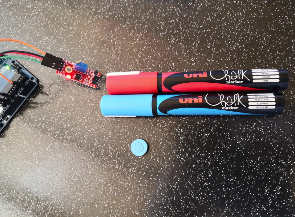
Hall sensor are sensitive to polarity, so to better view sides for my tests, I use chalk marker to color one side in blue and another in red :
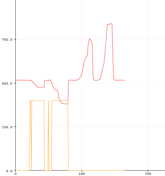
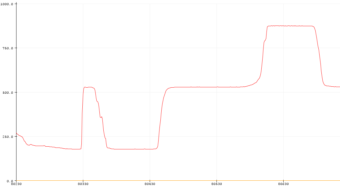
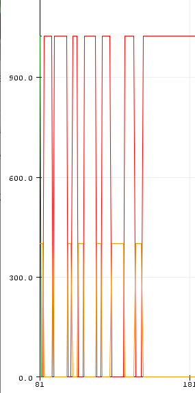
It’s interesting to see logic is inverted, it’s HIGH on digital pin when analogic values go down and LOW on digital when values go up (RED is analogRead and ORANGE is digital).
When I put BLUE side in front of sensor values go down & digital high, when I put RED values go up and digital low. Threshold can be adjusted with the screw on the blue part.
Another hall sensor (analog)
An analogic hall sensor
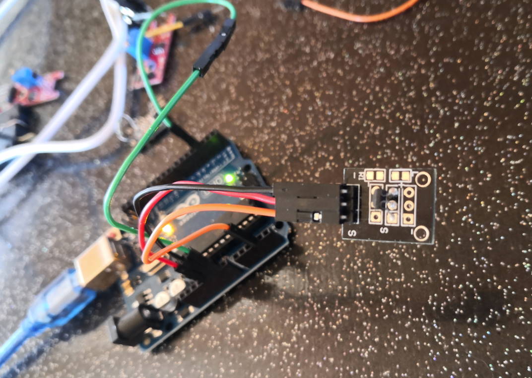
Wiring :
- S on ORANGE (analog)
- middle on RED (+5v)
- (-) on BLACK (gnd)
I also plug GREEN to gnd (digital) to clean values on serial monitor.
Same result like the analog output of the red version, it’s depend on polarity of magnet.
It can also be plugged on a digital pin but it just react on 1 side by switching from HIGH to LOW.
Wiring :
- S on GREEN (digital)
- middle on RED (+5v)
- (-) on BLACK (gnd)
I also plug pin 3 to gnd (digital) to clean values on serial monitor.
Another Hall sensor (digital only)
Wiring :
- S on GREEN (digital)
- middle on RED (+5v)
- (-) on BLACK (gnd)
I also plug pin 3 to gnd (digital) to clean values on serial monitor. It works like the analog I test before (DOWN when a magnet is near AND on the correct side) but I have a led that show the digital state on it (LED is on when DOWN)
I test in analog
Wiring :
- S on ORANGE (analog)
- middle on RED (+5v)
- (-) on BLACK (gnd)
I also plug GREEN to gnd (digital) to clean values on serial monitor.
But I just have 2 states (an barely HIGH and a LOW), it change only when I a magnet is near AND in the correct side, I can’t know if the magnet is near and on the other side.
Reed switch
It’s like a switch but activated by magnetic field. I know this switch because one of my car (Toyota MR2 ‘91 with 2l 3sge motor) have a part now very rare and often broken : the oil level sensor (because oil sensor have to be removed BEFORE oil pan on this motor unlike others) and in my tries to reverse engineering it and built compliant replacement part I have seen there’s an reed switch inside.
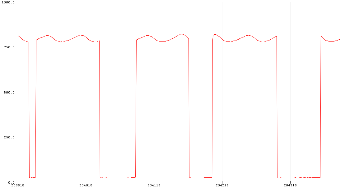
In analog or digital, I have only full open or full closed like a switch.
Digital output is inverted to analog. It’s high when I approach a magnet and low when there is no magnet. Threshold can be adjusted with the screw on the blue part.
Another Reed Switch
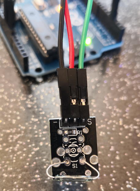
Normal wiring is :
- (-) to BLACK
- middle to RED (+5v)
- S to GREEN (digital)
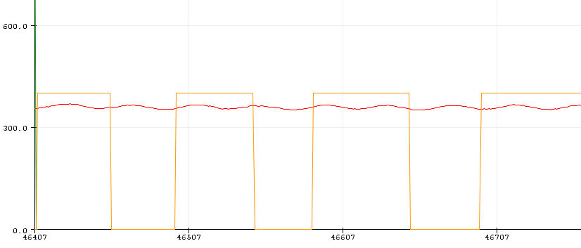
ORANGE is digital. RED is analog (no plug, just noise). it goes HIGH when a magnet is near and it goes LOW when there’s no magnet.
But you can also modify wiring and plug like this :
- (-) to GREEN (digital)
- middle to RED (+5v)
- S to BLACK (gnd)
And logic is inverted :
ORANGE is digital. RED is analog (no plug, just noise). With this alternate wiring, it goes LOW when a magnet is near and it goes HIGH when there’s no magnet.
Group assignment
Potentiometer
Wiring :
- one side on RED (+5v)
- other side on BLACK (gnd)
- middle on ORANGE (analog)
I write another code to get range :
/*****************************
 * Getting max analog values
 *
 * @author Florent Lemaire
 *
 *****************************/

int analogPin = A3; // define the analog sensor interface
int valAnalog, minVal, maxVal;

FILE serial_stdout;//for quicker stdout instead of many serial.print and println

// Function that printf and related will use to print
int serial_putchar(char c, FILE* f) {
    if (c == '\n') serial_putchar('\r', f);
    return Serial.write(c) == 1? 0 : 1;
}

void setup ()
{
  Serial.begin(9600); // initialize serial communication at 9600 bits per second:
  pinMode (analogPin, INPUT) ; // define input for analog

  // Set up stdout
  fdev_setup_stream(&serial_stdout, serial_putchar, NULL, _FDEV_SETUP_WRITE);
  stdout = &serial_stdout;
}
void loop ()
{
  delay(20);
  valAnalog = analogRead(analogPin);
  maxVal = (valAnalog > maxVal) ? valAnalog : maxVal ;
  minVal = (valAnalog < minVal) ? valAnalog : minVal ;

  printf("Min : %d Max : %d Current : %d\n", minVal, maxVal, valAnalog); //serial output in only one line :)
}
Then I launch serial monitor, play with potentiometer and here the result :
Min : 0 Max : 1023 Current : 883
Min : 0 Max : 1023 Current : 867
Min : 0 Max : 1023 Current : 868
Min : 0 Max : 1023 Current : 886
Min : 0 Max : 1023 Current : 876
Min : 0 Max : 1023 Current : 848
Min : 0 Max : 1023 Current : 854
Min : 0 Max : 1023 Current : 870
Min : 0 Max : 1023 Current : 874
Min : 0 Max : 1023 Current : 864
Min : 0 Max : 1023 Current : 860
Min : 0 Max : 1023 Current : 868
Min : 0 Max : 1023 Current : 873
Min : 0 Max : 1023 Current : 868
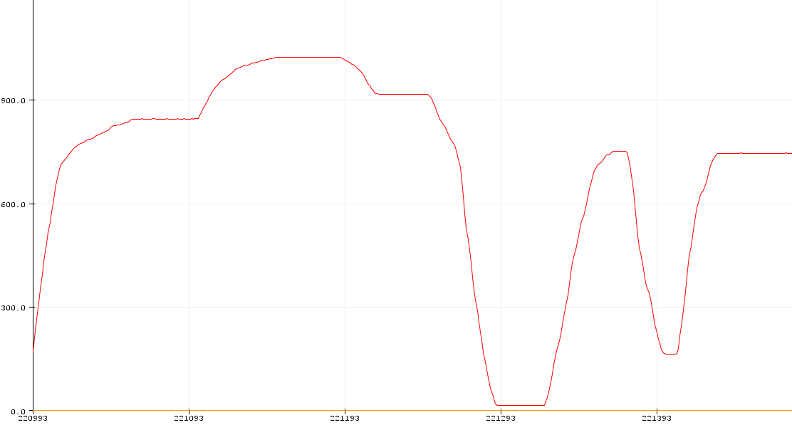
Joystick
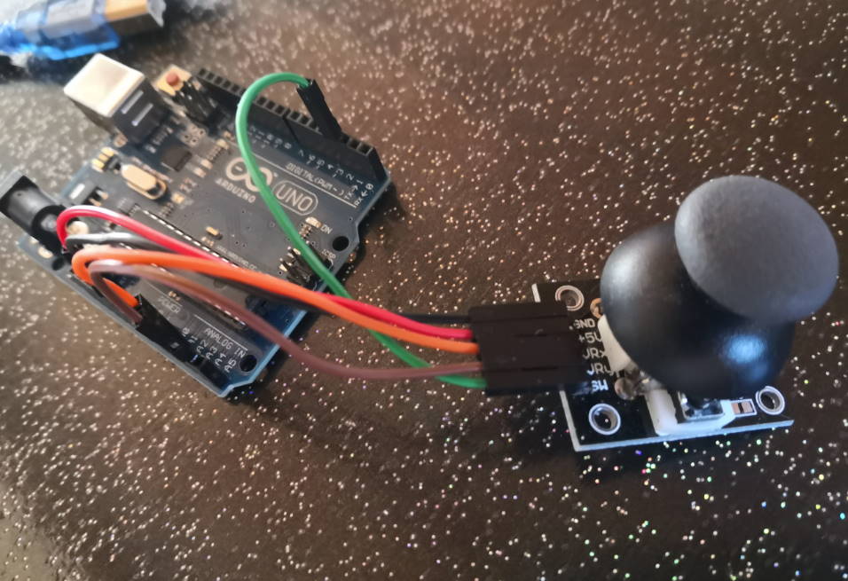
Wiring :
- GND to BLACK (gnd)
- +5V to RED (+5v)
- VRx to ORANGE (A3)
- VRy to BROWN (A4)
- SW to GREEN (3)
I wrote another specific code, taking pleasure for the output inline ^^
/*****************************
 * Getting Joystick values
 *
 * @author Florent Lemaire
 *
 *****************************/

// define the analog sensor interface
int xPin = A3;
int yPin = A4;
int button = 3;

FILE serial_stdout; //for quicker stdout instead of many serial.print and println

// Function that printf and related will use to print
int serial_putchar(char c, FILE* f) {
    if (c == '\n') serial_putchar('\r', f);
    return Serial.write(c) == 1? 0 : 1;
}

void setup ()
{
  Serial.begin(9600); // initialize serial communication at 9600 bits per second:
  // define inputs
  pinMode (xPin, INPUT);
  pinMode (yPin, INPUT);
  pinMode (button, INPUT);

  // Set up stdout
  fdev_setup_stream(&serial_stdout, serial_putchar, NULL, _FDEV_SETUP_WRITE);
  stdout = &serial_stdout;
}
void loop ()
{
  delay(20);
  printf("X: %d, Y: %d, Button pressed: %s\n", analogRead(xPin), analogRead(yPin), digitalRead(button)? "YES" : "NO");
}
Output :
X: 526, Y: 511, Button pressed: NO
X: 526, Y: 511, Button pressed: YES
X: 0, Y: 843, Button pressed: NO
X: 0, Y: 640, Button pressed: NO
X: 0, Y: 511, Button pressed: NO
X: 526, Y: 66, Button pressed: YES
X: 526, Y: 263, Button pressed: YES