9. Embedded programming
individual assignment:
      read a microcontroller data sheet
      program your board to do something,
         with as many different programming languages
         and programming environments as possible
   group assignment:
      compare the performance and development workflows
         for other architectures
SubarUSB as remote control ???
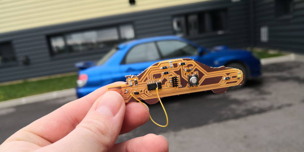
This I will make a TV B Gone alike with my board of week 07.
What’s TV B Gone? It’s a fancy gadget of early 2000’s used to mass shutdown TV. It send in loop shutdown code of many TV brand.

First flash and dev on SAMD11C
A quick remember of what I’ve already done on week 07.
For the first flash, I use an Atmel-ICE programmer. I install Atmel studio (version 7 at this time) in order to have all the drivers for using it (may be a lighter installer is available with only drivers?).
Let’s go to flash. After installing all Atmel drivers for the flash box. Plug the board on the SAM connector with a 10pin cable, green LED. YES!!!
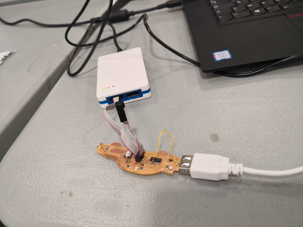
First I have to flash the bootloader in SWD mode with CMSIS-DAP programmer (Formerly Atmel EDBG programmer)
ebdg.exe -b -t samd11 -pv -f sam_ba_Generic_D11C14A_SAMD11C14A.bin
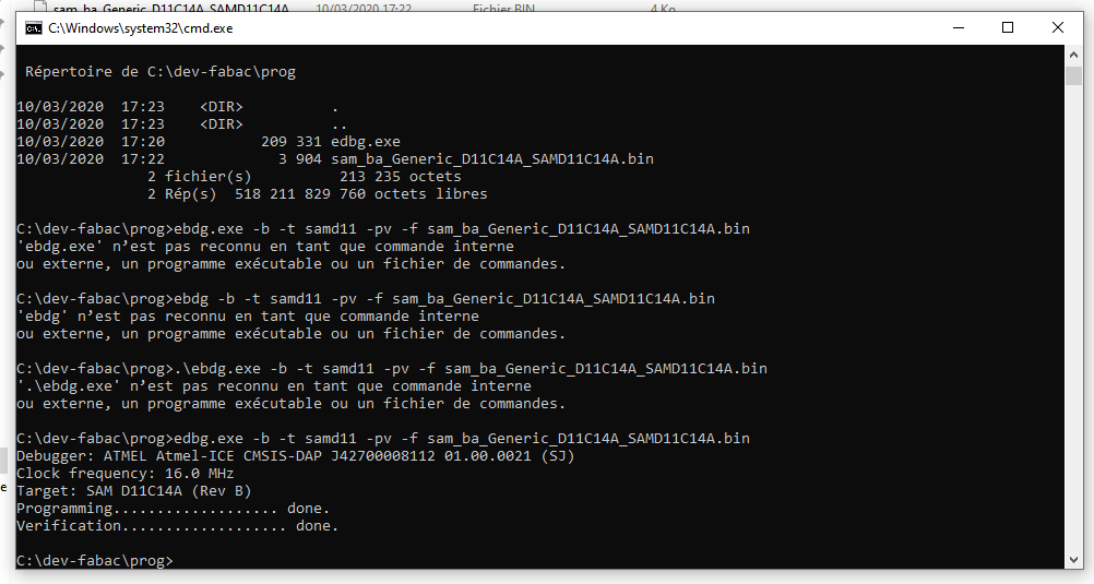
Flash successful! Atmel ICE programmer can now be removed because it’s not needed anymore. You can program the board directly with the USB port (thanks to bootloader but you also lose 4KB and you now have only 12KB free).
I use the arduino software. You have to install the boards, first add a new URL in arduino software for boards : https://www.mattairtech.com/software/arduino/beta/package_MattairTech_index.json
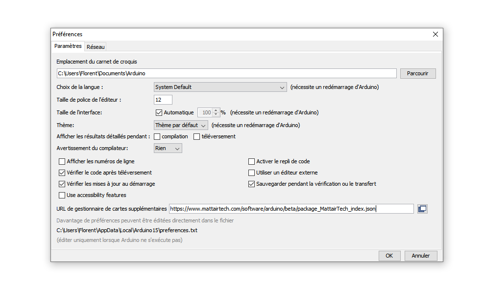
Now I can install “MattairTech SAM D|L|C core for arduino”.
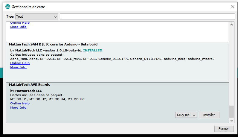
Correct board doesn’t appear yet. You to go one more time to board manager, see update available et update “MattairTech SAM D|L|C core for arduino” in a beta version (here 1.6.18-beta-b1).
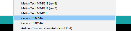
Now you can set the correct board Generic D11C114A
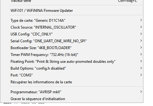
Here my setting before flashing the board with arduino.
I first test the Neil code that blink one of my LED. Then I start from the blink arduino example and referring to the pin I plug my white and red LED, I do my own code :
// the setup function runs once when you press reset or power the board
void setup() {
  // initialize my two led pin as output.
  pinMode(5, OUTPUT);
  pinMode(4, OUTPUT);
}

// the loop function runs over and over again forever
void loop() {
  digitalWrite(5, HIGH);
  digitalWrite(4, HIGH);// turn the LED on (HIGH is the voltage level)
  delay(1000);                       // wait for a second
  digitalWrite(5, LOW);
  digitalWrite(4, LOW);// turn the LED off by making the voltage LOW
  delay(1000);                       // wait for a second
}
Then I flash my board directly from Arduino IDE and my board plugged to an USB port.
Le croquis utilise 9400 octets (76%) de l'espace de stockage de programmes. Le maximum est de 12288 octets.
Atmel SMART device 0x10030006 found
Device       : ATSAMD11C14A
Chip ID      : 10030006
Version      : v2.0 Nov 22 2017 12:56:25
Address      : 4096
Pages        : 192
Page Size    : 64 bytes
Total Size   : 12KB
Planes       : 1
Lock Regions : 16
Locked       : none
Security     : false
Boot Flash   : true
BOD          : true
BOR          : true
Erase flash
done in 0.777 seconds

Write 9752 bytes to flash (153 pages)

[                              ] 0% (0/153 pages)
[==                            ] 9% (15/153 pages)
[=====                         ] 19% (30/153 pages)
[========                      ] 29% (45/153 pages)
[===========                   ] 39% (60/153 pages)
[==============                ] 49% (75/153 pages)
[=================             ] 58% (90/153 pages)
[====================          ] 68% (105/153 pages)
[=======================       ] 78% (120/153 pages)
[==========================    ] 88% (135/153 pages)
[============================= ] 98% (150/153 pages)
[==============================] 100% (153/153 pages)
done in 7.142 seconds

Verify 9752 bytes of flash

[                              ] 0% (0/153 pages)
[==                            ] 9% (15/153 pages)
[=====                         ] 19% (30/153 pages)
[========                      ] 29% (45/153 pages)
[===========                   ] 39% (60/153 pages)
[==============                ] 49% (75/153 pages)
[=================             ] 58% (90/153 pages)
[====================          ] 68% (105/153 pages)
[=======================       ] 78% (120/153 pages)
[==========================    ] 88% (135/153 pages)
[============================= ] 98% (150/153 pages)
[==============================] 100% (153/153 pages)
Verify successful
done in 0.059 seconds
CPU reset.
And voilà
Reading datasheet of SAMD11C
First I go to fab inventory to get the digikey reference my SAMD version : ATSAMD11C14A-SSUTCT-ND
According to this page on digikey, the full name of component is : ATSAMD11C14A-SSUT
In the datasheet available here I extract the following information on my version. With these, you can quickly find what’s in your version with the name :
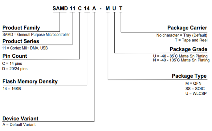
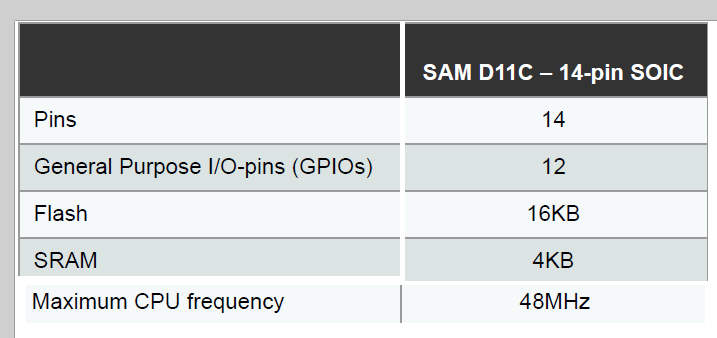
So the quick spec of mine :
AT is for the Atmel family SAMD : general purpose microcontroller 11 : Cortex M0+ DMA, USB C : 14 pins 14 : 16 KB A : default variant SS : SOIC U : -40 to 85 °C Matte Sn Plating T : tape and reel
The block diagram is very interesting, it’s very similar to a little embedded computer :
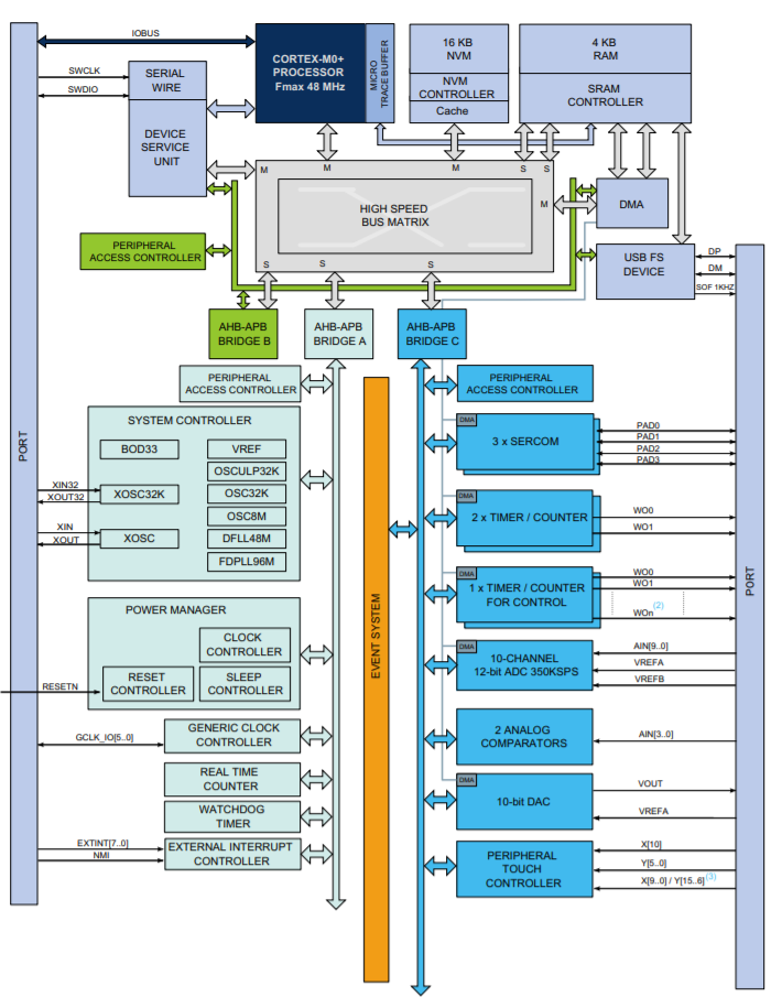
You have the processor (here a Cortex M0+, like a Intel/AMD computer processor). Others parts are like a motherboard with different bus, bridges, controllers. Some are for access memory (SRAM controller for RAM, NVM controller for flash) Serial wire is for programming and debugging (even if you can program by USB after flashing a bootloader) Dedicated circuits are also present like timer, analog comparator, DAC.
Some information interesting for me at this time :
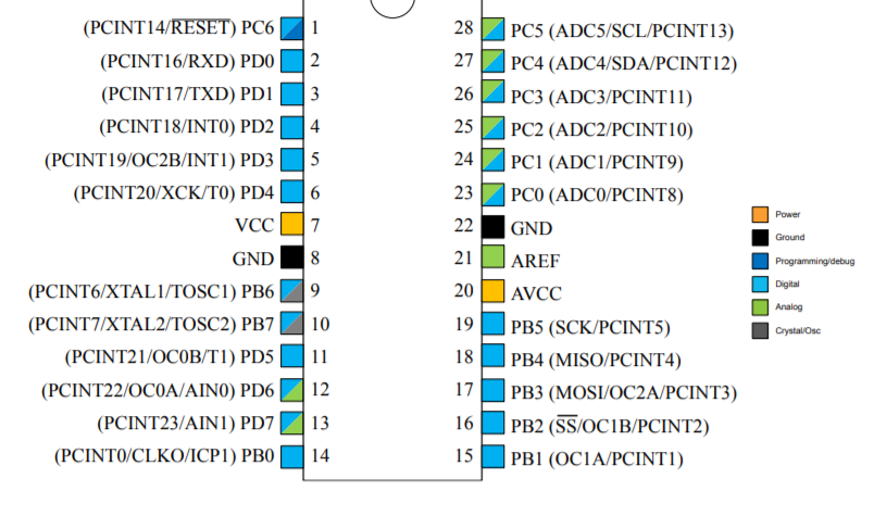
The pinout, you can see a dot which is very useful when it’s time to solder the real component because you have to put it in the correct way :
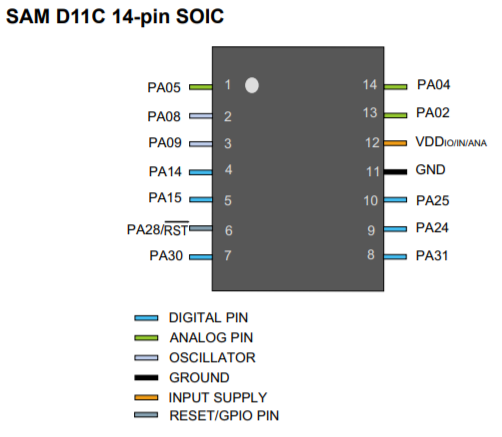
Some PIN are digital only(high/low), some are analog (can have a range of values, but can be used also as digital pin), VDD and GND are strictly reserved. PA28 can be used as GPIO ou reset PIN. As we see on table, with correct configuration 12 GPIO are available.
Next, SAMD11C as universal remote ?
On my board, I’ve 3 LED. The first 2 LED I’ve already use are the white and the red. The 3rd LED is IR and I also have a button.
Quick brief on my pinout
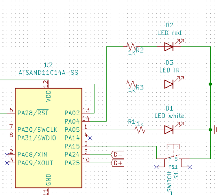
White LED on PA05 / 1 Red LED on PA04 / 14 IR LED on PA02 / 13 Button on PA15 / 5
I finally put 5k resistor instead of 1k.
First attempt, shutdown TV in a loop.
After many searches, finally I choose to use this example as start for writing my own code.
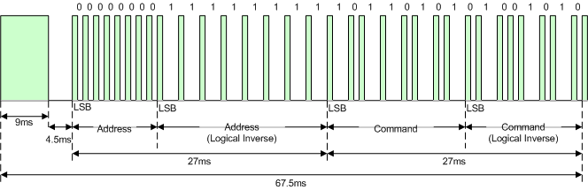
There are many protocol for IR remote (as RC5, RC6 etc.), for my TV (LG 86UK6500PLA), by mixing different sources it seems to be NEC protocol.
Nec InfraRed protocol is explained here.
When a key is pressed on the remote controller, the message transmitted consists of the following, in order:
a 9ms leading pulse burst (16 times the pulse burst length used for a logical data bit)
a 4.5ms space
the 8-bit address for the receiving device
the 8-bit logical inverse of the address
the 8-bit command
the 8-bit logical inverse of the command
a final 562.5µs pulse burst to signify the end of message transmission.
For IR codes, I’ve tested many shutdown code from different sources and finally I’ve found this for my LG TV. I’ve test the on/off and it works. Here the code for on/off in a loop. I found later that other code I’ve found where also correct but there a trick because code need to be switched each 4 bytes block from Most Significant Byte (MSB) to Least Significant Byte (LSB).
I use red led to see when board if powered. White LED is active when I’m not sending on/off code on IR, by this I see when I’m sending IR code and when I’m waiting. Waiting time is set to 5s.
#define IRLEDpin  2 // IR led for driving TV
#define rLEDpin   4 // red LED
#define wLEDpin   5 // white LED
#define BITtime   562 //length of the carrier bit in microseconds
//put your own code here - 4 bytes (ADDR1 | ADDR2 | COMMAND1 | COMMAND2)
unsigned long IRcode=0x20DF10EF; // power for LG

void setup() {
  // initialize IR LED as output.
  pinMode(IRLEDpin, OUTPUT);
  digitalWrite(IRLEDpin, LOW);

  // init red & white
  pinMode(wLEDpin, OUTPUT);
  pinMode(rLEDpin, OUTPUT);
  digitalWrite(rLEDpin, HIGH); //init at startup to see if board is powered and drain some current

  // for log
  Serial.begin(9600);
}

// Ouput the 38KHz carrier frequency for the required time in microseconds
// This is timing critical
void IRcarrier(unsigned int IRtimemicroseconds)
{
  for(int i=0; i < (IRtimemicroseconds / 26); i++)
    {
    digitalWrite(IRLEDpin, HIGH);   //turn on the IR LED
    //NOTE: digitalWrite takes about 3.5us to execute, so we need to factor that into the timing.
    //Serial.print("high");
    delayMicroseconds(9);          //delay for 13us (9us + digitalWrite), half the carrier frequnecy
    digitalWrite(IRLEDpin, LOW);    //turn off the IR LED
    //Serial.print("low");
    delayMicroseconds(9);          //delay for 13us (9us + digitalWrite), half the carrier frequnecy
    }
}

//Sends the IR code in 4 byte NEC format
void IRsendCode(unsigned long code)
{
  //send the leading pulse
  IRcarrier(9000);            //9ms of carrier
  delayMicroseconds(4500);    //4.5ms of silence

  //send the user defined 4 byte/32bit code
  for (int i=0; i<32; i++)            //send all 4 bytes or 32 bits
    {
    IRcarrier(BITtime);               //turn on the carrier for one bit time
    if (code & 0x80000000)            //get the current bit by masking all but the MSB
      delayMicroseconds(3 * BITtime); //a HIGH is 3 bit time periods
    else
      delayMicroseconds(BITtime);     //a LOW is only 1 bit time period
     code<<=1;                        //shift to the next bit for this byte
    }
  IRcarrier(BITtime);                 //send a single STOP bit.
}

void loop()                           //main code
{
  IRsendCode(IRcode);
  digitalWrite(5, HIGH);
  delay(5000);
  digitalWrite(5, LOW);
}
ON / OFF my TV with my button
Like I do with an classical Arduino, I can read pin status in a loop or use interrupt. I don’t find for and SAMD which pin can be interrupted and my board is already soldered since 2 weeks so I just try and I will see!
Interrupt VS loop ?
It depends on how quickly you want the Microcontroller to respond to a change. An interrupt is handled immediately… the MC will stop what its doing (or wake up from sleep) and service the interrupt without delay… unless the MC is already servicing an interrupt, then the new interrupt will be acted on once the MC is done with the current interrupt.
Checking for a change in a loop works too…but you need to wait for the loop to circle back before you know if there was a change or not…and, you can put the MC to sleep…as it won’t be running through a loop while asleep.
Loop is easier to debug because you now in advance when/what, interrupt… interrupts ^^
So by following this example, I try with interrupt :
#define IRLEDpin  2 // IR led for driving TV
#define rLEDpin   4 // red LED
#define wLEDpin   5 // white LED
#define buttonPin 15 // button
#define BITtime   562 //length of the carrier bit in microseconds
//put your own code here - 4 bytes (ADDR1 | ADDR2 | COMMAND1 | COMMAND2)
unsigned long IRcode=0x20DF10EF; // power for LG
unsigned long discretePOFF = 0x20DFA35C;

void setup() {
  // initialize IR LED as output.
  pinMode(IRLEDpin, OUTPUT);
  digitalWrite(IRLEDpin, LOW);

  // init red & white
  pinMode(wLEDpin, OUTPUT);
  pinMode(rLEDpin, OUTPUT);
  digitalWrite(rLEDpin, HIGH); //init at startup to see if board is powered and drain some current

  // for log
  Serial.begin(9600);

  // plugin button
  pinMode(buttonPin, INPUT_PULLUP);
  attachInterrupt(digitalPinToInterrupt(buttonPin), shutUpAndDown, LOW);
}

void shutUpAndDown() {
  digitalWrite(wLEDpin, HIGH);
  IRsendCode(IRcode);
  digitalWrite(wLEDpin, LOW);
  Serial.println();
  delayMicroseconds(40000);
}

// Ouput the 38KHz carrier frequency for the required time in microseconds
// This is timing critial and just do-able on an Arduino using the standard I/O functions.
// If you are using interrupts, ensure they disabled for the duration.
void IRcarrier(unsigned int IRtimemicroseconds)
{
  for(int i=0; i < (IRtimemicroseconds / 26); i++)
    {
    digitalWrite(IRLEDpin, HIGH);   //turn on the IR LED
    //NOTE: digitalWrite takes about 3.5us to execute, so we need to factor that into the timing.
    Serial.print("high");
    delayMicroseconds(9);          //delay for 13us (9us + digitalWrite), half the carrier frequnecy
    digitalWrite(IRLEDpin, LOW);    //turn off the IR LED
    Serial.print("low");
    delayMicroseconds(9);          //delay for 13us (9us + digitalWrite), half the carrier frequnecy
    }
}

//Sends the IR code in 4 byte NEC format
void IRsendCode(unsigned long code)
{
  //send the leading pulse
  IRcarrier(9000);            //9ms of carrier
  delayMicroseconds(4500);    //4.5ms of silence

  //send the user defined 4 byte/32bit code
  for (int i=0; i<32; i++)            //send all 4 bytes or 32 bits
    {
    IRcarrier(BITtime);               //turn on the carrier for one bit time
    if (code & 0x80000000)            //get the current bit by masking all but the MSB
      delayMicroseconds(3 * BITtime); //a HIGH is 3 bit time periods
    else
      delayMicroseconds(BITtime);     //a LOW is only 1 bit time period
     code<<=1;                        //shift to the next bit for this byte
    }
  IRcarrier(BITtime);                 //send a single STOP bit.
}

void loop()                           //some demo main code
{
  // do nothiiiiiiiiiiiiiiiing
}
Flashing the board (with IDE and toolchain)
Le croquis utilise 10040 octets (81%) de l'espace de stockage de programmes. Le maximum est de 12288 octets.
Atmel SMART device 0x10030006 found
Device       : ATSAMD11C14A
Chip ID      : 10030006
Version      : v2.0 Nov 22 2017 12:56:25
Address      : 4096
Pages        : 192
Page Size    : 64 bytes
Total Size   : 12KB
Planes       : 1
Lock Regions : 16
Locked       : none
Security     : false
Boot Flash   : true
BOD          : true
BOR          : true
Erase flash
done in 0.276 seconds

Write 10392 bytes to flash (163 pages)

[                              ] 0% (0/163 pages)
[==                            ] 9% (16/163 pages)
[=====                         ] 19% (32/163 pages)
[========                      ] 29% (48/163 pages)
[===========                   ] 39% (64/163 pages)
[==============                ] 49% (80/163 pages)
[=================             ] 58% (96/163 pages)
[====================          ] 68% (112/163 pages)
[=======================       ] 78% (128/163 pages)
[==========================    ] 88% (144/163 pages)
[============================= ] 98% (160/163 pages)
[==============================] 100% (163/163 pages)
done in 3.151 seconds

Verify 10392 bytes of flash

[                              ] 0% (0/163 pages)
[==                            ] 9% (16/163 pages)
[=====                         ] 19% (32/163 pages)
[========                      ] 29% (48/163 pages)
[===========                   ] 39% (64/163 pages)
[==============                ] 49% (80/163 pages)
[=================             ] 58% (96/163 pages)
[====================          ] 68% (112/163 pages)
[=======================       ] 78% (128/163 pages)
[==========================    ] 88% (144/163 pages)
[============================= ] 98% (160/163 pages)
[==============================] 100% (163/163 pages)
Verify successful
done in 0.054 seconds
CPU reset.
It works !
Range is awful, only few centimeters. Not very powerful IR LED…
Push it further
Due to COVID-19 and shutdown of AgriLab, I can’t make a new board with more powerful LED. To verify if my IR LED of my SAMD11C send correct data, I’ve quickly build on an Arduino Uno an IR test board & repeater :
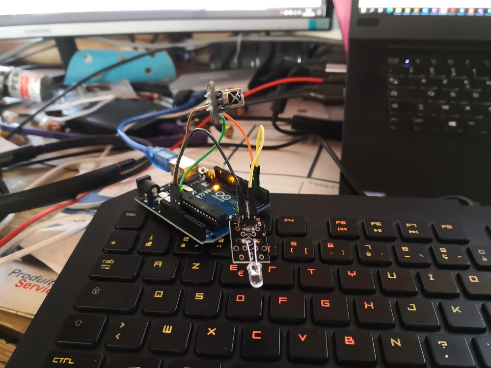
Here my code (I’ve found code here and add some change to debug, it use the library IRremote) :
#include <IRremote.h>

int RECV_PIN = 4;
IRrecv irrecv(RECV_PIN);
IRsend irsend; // Defaults to pin 3
decode_results results;
unsigned int rawCodes[RAWBUF];

void setup(){
  Serial.begin(9600);
  irrecv.enableIRIn();
  Serial.println("Info    : Infrared Decoder and Extender");
  Serial.println("Version : 1.0");
  Serial.println("---------------------------------------");
}

void loop(){
  // IR Extender
  if (irrecv.decode(&results)) {
    //Serial.println(results.value, HEX);
    int codeLen = results.rawlen - 1;
    for (int i = 1; i <= codeLen; i++) {
      if (i % 2) {
        // Mark
        rawCodes[i - 1] = results.rawbuf[i]*USECPERTICK - MARK_EXCESS;
        //Serial.print(" m");
      }
      else {
        // Space
        rawCodes[i - 1] = results.rawbuf[i]*USECPERTICK + MARK_EXCESS;
        //Serial.print(" s");
      }
      //Serial.print(rawCodes[i - 1], DEC);
    }
    irsend.sendRaw(rawCodes, codeLen, 38);
    irrecv.enableIRIn();
    irrecv.resume(); // Receive the next value
    dump(&results);
  }
}

// Dump results
void dump(decode_results *results) {
  int count = results->rawlen;
  if (results->decode_type == UNKNOWN) {
    Serial.print("Unknown encoding: ");
  }
  else if (results->decode_type == NEC) {
    Serial.print("Decoded NEC: ");
  }
  else if (results->decode_type == SONY) {
    Serial.print("Decoded SONY: ");
  }
  else if (results->decode_type == RC5) {
    Serial.print("Decoded RC5: ");
  }
  else if (results->decode_type == RC6) {
    Serial.print("Decoded RC6: ");
  }else if (results->decode_type == JVC) {
    Serial.print("Decoded JVC: ");
  }
  Serial.print(results->value, HEX);
  Serial.print(" (");
  Serial.print(results->bits, DEC);
  Serial.println(" bits)");
  Serial.print("Raw (");
  Serial.print(count, DEC);
  Serial.print("): ");

  for (int i = 0; i < count; i++) {
    if ((i % 2) == 1) {
      Serial.print(results->rawbuf[i]*USECPERTICK, DEC);
    }
    else {
      Serial.print(-(int)results->rawbuf[i]*USECPERTICK, DEC);
    }
    Serial.print(" ");
  }
  Serial.println("");
}
I can verify IR code send by my SubarUSB, and YES it works!!!
Decoded NEC: 20DF10EF (32 bits)
Raw (68): -5350 10350 -4500 650 -550 650 -550 650 -1700 650 -550 600 -600 600 -600 600 -600 600 -550 650 -1700 650 -1700 650 -550 650 -1650 650 -1700 650 -1650 650 -1700 650 -1700 600 -600 600 -600 600 -550 650 -1700 650 -550 600 -600 600 -600 600 -600 650 -1650 650 -1700 600 -1750 600 -600 600 -1700 650 -1700 600 -1700 650 -1700 650
I reverse engineered my original remote control and I’ve got same code!
I test repeater mode by sending signal from SubarUSB IR led to IR receiver of arduino and push back to TV with IR led plugged on the Arduino and now I’ve got better range (few meters).
Use another IDE
As a former developer with big experience in Java, I spent many times on Eclipse IDE. It’s an opensource software written in Java and mainly dedicated to it but not only and it can work for many languages.

Here I use GNU MCU/ARM Eclipse. I finally haven’t time to finish for this week but I wanted to make an IR remote control with an ESP8266 (wemos D1 mini) with html page on webserver over wifi.
Group assignment
Compare the performance and development workflows for other architectures
Atmel SAMD11C 14 pin SOIC : 48Mhz, 32bit, 16KB flash, 4KB SRAM, up to 12 GPIO
Atmel SAMD11D 20 pin SOIC : 48Mhz, 32 bit, 16KB flash, 4KB SRAM, up to 18 GPIO
Once we flash a bootloader with an programmer like Atmel ICE, it can’t directly be flashed in USB and coded in Arduino IDE.
On the Arduino Uno datasheet available here, we can see it use an Atmel ATmega328. On the datasheet of ATmega328 available here we can see following informations :
Atmel ATmega328 PDIP : 20Mhz (limited to 16Mhz in Arduino uno), 8bit, 32KB flash, 2KB SRAM, 1KB EEPROM, up to 23 GPIO (8 analog, 15 digital only).
Atmel can’t be directly programmed by USB port, that’s why arduino board embed an Atmega8U2 for that.