Assignment 8: Embedded Programming
Project Description
Explore Embedded Programming
Assignment Details
- Group Assignment:
- Compare the performance and development workflows for other architectures
- Individual assignment:
- Read a microcontroller data sheet
- Program your board to do something, with as many different programming languages and programming environments as possible
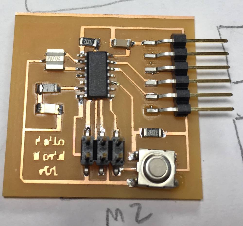
As part of Assignment 6, I created two different versions of a program to blink the LED based on the switch being up or pressed. I used the used the Arduino IDE to create the files and to push the code to the ATTiny44 via the SPI programmer. This validated that the processor, LED and switch worked. The assignment 6 page shows a video of the execution of each program.
The goal for this week was to:
- Read the ATTiny44 Datasheet
- Test the Serial interface on the Hello World board
- Integrate the switch and LED with the Serial Interface
- Create code that leverages interrupts
- Install and test the AVR CrossPack tool chain and write AVR C code
Read the ATTiny44 Datasheet
I used the book AVR Programming: Learning to Write Software for Hardware as a reference for learning how to program using the AVR tools.
The book made the comment that a datasheet should be viewed more as a "dictionary" rather than a novel. Reading it cover to cover can be pretty dry, but it is a great source of information if you know what you are looking for. In this case, I used the Pin Configuration diagrams to translate the physical pin position to the local port and port pin number. The section on interrupts was needed to determine the bit masks needed to set the right registers. The other information was interesting but not as useful at my current level of understanding.
Test the Serial interface on the Hello World board using the Arduino IDE
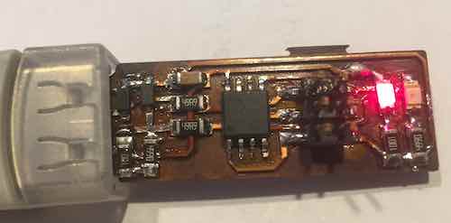
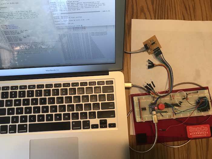
I have an existing FTDI board that I used to push code to a breadboard ATMega328p. I wired the FTDI to the serial pins on the Hello World board and connected the other side to my computer via the USB cable.
My intial tool chain went from writing code in the Arduino IDE, to pushing the code via the SPI programmer to the board. To begin with I played with using the Serial Monitor in the Arduino IDE as the Serial interface. The Arduino IDE can only be connected to one port at a time. So to switch between pushing code via ICSP programmer and viewing the results in the Serial Monitor, I had to unplug the programmer and change the port to the FTDI port. On the programming side, the ATTiny44 does not have support hardware serial, so I needed to load the SoftwareSerial library to access the hardware pins. Next it took some experimenting to find the the right software pins for TX and RX needed in the SoftwareSerial constructor. I rapidly found that plugging and unplugging USB cables was becoming cumbersome, so I switched to the MacOS Screen command as my serial terminal. This allowed code pushes to be followed by debugging without changing cable configurations.
Integrate the switch and LED with the Serial Interface using the Arduino IDE, Arduino C using the Arduino Libraries.
I used Neil's echo program as a model, but wanted to do something that also included the switch and the LED. The following program was written to meet this objective. It used the SoftwareSerial library to read and write to the serial interface with my computer. Characters typed in the Screen terminal are read by the program and echoed back to the Screen terminal with a line number. The LED is blinked each time a character is read. When the switch is pressed, a CR is written to the terminal, the line number is incremented and new characters are then written to the new line.
#include <SoftwareSerial.h>

const int buttonPin = 3;     // the number of the pushbutton pin
const int ledPin =  7;      // the number of the LED pin
int buttonState = 0;
int lineNum = 0;

SoftwareSerial serial(1, 0);
void setup() {
  // put your setup code here, to run once:
  serial.begin(9600);
    // initialize the LED pin as an output:
  pinMode(ledPin, OUTPUT);
  // initialize the pushbutton pin as an input:
  pinMode(buttonPin, INPUT);

   serial.println();
   serial.print(lineNum);
   serial.print(": ");
   lineNum++;

}

void loop() {
  // while there is data coming in, read it
  // and send to the hardware serial port:
  if (serial.available()) {
    digitalWrite(ledPin,HIGH);
    char c = serial.read();
    serial.print(c);

  }
  buttonState = digitalRead(buttonPin);
  if (buttonState == LOW) {
        serial.println();
        digitalWrite(ledPin,HIGH);
        serial.print(lineNum);
        serial.print(": ");
        lineNum++;
        //debounce the switch
        delay(500);
  }
  digitalWrite(ledPin,LOW);
}
Test the Serial interface on the Hello World board using the AVR C and AVRDUDE
The next objective was to do the same thing in C using the AVRDUDE and Makefiles. After installing the AVR CrossPack tool chain, I replicated compiling and deploying the hello.ftdi.44.echo.c program. These steps were intended to validate that the AVR development environment was installed and configured correctly.
petes-Air-7:week 8 pete$ make -f hello.ftdi.44.echo.c.make
avr-gcc -mmcu=attiny44 -Wall -Os -DF_CPU=20000000 -I./ -o hello.ftdi.44.echo.out hello.ftdi.44.echo.c
avr-objcopy -O ihex hello.ftdi.44.echo.out hello.ftdi.44.echo.c.hex;\
	avr-size --mcu=attiny44 --format=avr hello.ftdi.44.echo.out
AVR Memory Usage
----------------
Device: attiny44

Program:     758 bytes (18.5% Full)
(.text + .data + .bootloader)

Data:         64 bytes (25.0% Full)
(.data + .bss + .noinit)
Next the fuses were updated
	petes-Air-7:week 8 pete$ make -f hello.ftdi.44.echo.c.make program-usbtiny-fuses
avr-objcopy -O ihex hello.ftdi.44.echo.out hello.ftdi.44.echo.c.hex;\
	avr-size --mcu=attiny44 --format=avr hello.ftdi.44.echo.out
AVR Memory Usage
----------------
Device: attiny44

Program:     758 bytes (18.5% Full)
(.text + .data + .bootloader)

Data:         64 bytes (25.0% Full)
(.data + .bss + .noinit)


avrdude -p t44 -P usb -c usbtiny -U lfuse:w:0x5E:m

avrdude: AVR device initialized and ready to accept instructions

Reading | ################################################## | 100% 0.00s

avrdude: Device signature = 0x1e9207
avrdude: reading input file "0x5E"
avrdude: writing lfuse (1 bytes):

Writing | ################################################## | 100% 0.01s

avrdude: 1 bytes of lfuse written
avrdude: verifying lfuse memory against 0x5E:
avrdude: load data lfuse data from input file 0x5E:
avrdude: input file 0x5E contains 1 bytes
avrdude: reading on-chip lfuse data:

Reading | ################################################## | 100% 0.00s

avrdude: verifying ...
avrdude: 1 bytes of lfuse verified

avrdude: safemode: Fuses OK (H:FF, E:DF, L:5E)

avrdude done.  Thank you.
Finally the code was compiled, linked and deployed to the ATTiny
petes-Air-7:week 8 pete$ make -f hello.ftdi.44.echo.c.make program-usbtiny
avr-objcopy -O ihex hello.ftdi.44.echo.out hello.ftdi.44.echo.c.hex;\
	avr-size --mcu=attiny44 --format=avr hello.ftdi.44.echo.out
AVR Memory Usage
----------------
Device: attiny44

Program:     758 bytes (18.5% Full)
(.text + .data + .bootloader)

Data:         64 bytes (25.0% Full)
(.data + .bss + .noinit)


avrdude -p t44 -P usb -c usbtiny -U flash:w:hello.ftdi.44.echo.c.hex

avrdude: AVR device initialized and ready to accept instructions

Reading | ################################################## | 100% 0.00s

avrdude: Device signature = 0x1e9207
avrdude: NOTE: "flash" memory has been specified, an erase cycle will be performed
         To disable this feature, specify the -D option.
avrdude: erasing chip
avrdude: reading input file "hello.ftdi.44.echo.c.hex"
avrdude: input file hello.ftdi.44.echo.c.hex auto detected as Intel Hex
avrdude: writing flash (758 bytes):

Writing | ################################################## | 100% 0.82s

avrdude: 758 bytes of flash written
avrdude: verifying flash memory against hello.ftdi.44.echo.c.hex:
avrdude: load data flash data from input file hello.ftdi.44.echo.c.hex:
avrdude: input file hello.ftdi.44.echo.c.hex auto detected as Intel Hex
avrdude: input file hello.ftdi.44.echo.c.hex contains 758 bytes
avrdude: reading on-chip flash data:

Reading | ################################################## | 100% 1.00s

avrdude: verifying ...
avrdude: 758 bytes of flash verified

avrdude: safemode: Fuses OK (H:FF, E:DF, L:5E)

avrdude done.  Thank you.
The code did not work on the initial try. I opened up the code and found a few places where I needed to make changes to allow it to execute as expected. First I needed to revise the TX and RX pins
#define serial_pin_in (1 << PA1)   // <-- Changed Line
#define serial_pin_out (1 << PA0)  // <-- Changed Line
The program was providing a new line but not a carriage return, so the screen formating was messed up. I added this line to correct the problem.
while (1) {
get_char(&serial_pins, serial_pin_in, &chr);
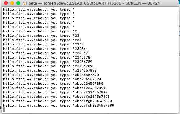
put_string(&serial_port, serial_pin_out, "hello.ftdi.44.echo.c: you typed \"");
buffer[index++] = chr;
if (index == (max_buffer-1))
index = 0;
put_string(&serial_port, serial_pin_out, buffer); // existing Code
put_char(&serial_port, serial_pin_out, 10); // existing Code
put_char(&serial_port, serial_pin_out, 13); // <-- Added Code
}
Here was the corresponding input and output in the screen terminal window.
To validate that I could use AVR C myself, I created a simple program to blink the LED. First I needed to figure out how to interact with the pin that controls the LED. In this case the pin is PA7. I used macros from the book and created this program.
#include <avr/io.h>
#include <util/delay.h>

#define LED      PA7
#define LED_DDR  DDRA
#define LED_PORT PORTA

#define DELAYTIME 20

#define setBit(sfr, bit)     (_SFR_BYTE(sfr) |= (1 << bit))
#define clearBit(sfr, bit)   (_SFR_BYTE(sfr) &= ~(1 << bit))
#define toggleBit(sfr, bit)  (_SFR_BYTE(sfr) ^= (1 << bit))

int main(void) {

  // Init
  setBit(LED_DDR, LED);                      /* set LED pin for output */

  // Mainloop
  while (1) {

    setBit(LED_PORT, LED);
    _delay_ms(DELAYTIME);

    clearBit(LED_PORT, LED);
    _delay_ms(DELAYTIME);

  }
  return 0;                                          /* end mainloop */
}
To validate that I understood the code, I changed the delay value and the LED blinked at a different rate.
Next step was to replicate the code written the Arduino C to turn on and off the LED with the switch. Here is the code:
#define SW		PA3
#define SW_DDR	DDRA
#define	SW_PORT	PORTA
#define SW_PIN	PINA

#define setBit(sfr, bit)     (_SFR_BYTE(sfr) |= (1 << bit))
#define clearBit(sfr, bit)   (_SFR_BYTE(sfr) &= ~(1 << bit))
#define toggleBit(sfr, bit)  (_SFR_BYTE(sfr) ^= (1 << bit))

int main(void) {
  // -------- Inits --------- //

	  // Init
  setBit(LED_DDR, LED);                      /* set LED pin for output */
  clearBit(SW_DDR, SW);		/* clear SW pin for input */


  // ------ Event loop ------ //
  while (1) {
    if (bit_is_clear(SW_PIN, SW)) {            /* look for button press */
                      /* equivalent to if ((PINA & (1 << PA3)) == 0 ){ */
        setBit(LED_PORT, LED);                                   /* pressed */
    }
    else {                                              /* not pressed */
    	clearBit(LED_PORT, LED);
    }
  }                                                  /* End event loop */
  return 0;
}
Integrate the switch and LED with the Serial Interface using the AVR tool chain
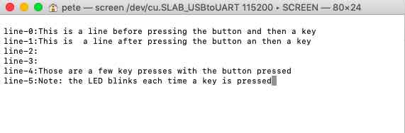
Next step was to modify Neil's code to support the ability to echo characters and insert CRs and LFs with line numbers by pressing the button. Because the get_char routine is modal, line feeds are generated after pressing the button and then pressing a key. The LED also binks each time a character is read by the Hello World board.
Here is the code:
//
//
// hello.ftdi.44.echo.c
//
// 115200 baud FTDI character echo, with flash string
//
// set lfuse to 0x5E for 20 MHz xtal
//
// Neil Gershenfeld
// 12/8/10
//
// (c) Massachusetts Institute of Technology 2010
// This work may be reproduced, modified, distributed,
// performed, and displayed for any purpose. Copyright is
// retained and must be preserved. The work is provided
// as is; no warranty is provided, and users accept all
// liability.
//

#include <avr/io.h>
#include <util/delay.h>
#include <avr/pgmspace.h>

#define led_pin_out     (1 << PA7)
#define led_direction  DDRA
#define led_port PORTA

#define sw_pin_in		(1 << PA3)
#define sw_direction	DDRA
#define	sw_port	PORTA
#define sw_pin	PINA

#define output(directions,pin) (directions |= pin) // set port direction for output
#define set(port,pin) (port |= pin) // set port pin
#define clear(port,pin) (port &= (~pin)) // clear port pin
#define pin_test(pins,pin) (pins & pin) // test for port pin
#define bit_test(byte,bit) (byte & (1 << bit)) // test for bit set
#define bit_delay_time 8.5 // bit delay for 115200 with overhead
#define bit_delay() _delay_us(bit_delay_time) // RS232 bit delay
#define half_bit_delay() _delay_us(bit_delay_time/2) // RS232 half bit delay
#define char_delay() _delay_ms(10) // char delay

#define serial_port PORTA
#define serial_direction DDRA
#define serial_pins PINA
#define serial_pin_in (1 << PA1)   // <-- Changed Line
#define serial_pin_out (1 << PA0)  // <-- Changed Line

#define max_buffer 25


void get_char(volatile unsigned char *pins, unsigned char pin, char *rxbyte) {
   //
   // read character into rxbyte on pins pin
   //    assumes line driver (inverts bits)
   //
   *rxbyte = 0;
   while (pin_test(*pins,pin))
      //
      // wait for start bit
      //
      ;
   //
   // delay to middle of first data bit
   //
   half_bit_delay();
   bit_delay();
   //
   // unrolled loop to read data bits
   //
   if pin_test(*pins,pin)
      *rxbyte |= (1 << 0);
   else
      *rxbyte |= (0 << 0);
   bit_delay();
   if pin_test(*pins,pin)
      *rxbyte |= (1 << 1);
   else
      *rxbyte |= (0 << 1);
   bit_delay();
   if pin_test(*pins,pin)
      *rxbyte |= (1 << 2);
   else
      *rxbyte |= (0 << 2);
   bit_delay();
   if pin_test(*pins,pin)
      *rxbyte |= (1 << 3);
   else
      *rxbyte |= (0 << 3);
   bit_delay();
   if pin_test(*pins,pin)
      *rxbyte |= (1 << 4);
   else
      *rxbyte |= (0 << 4);
   bit_delay();
   if pin_test(*pins,pin)
      *rxbyte |= (1 << 5);
   else
      *rxbyte |= (0 << 5);
   bit_delay();
   if pin_test(*pins,pin)
      *rxbyte |= (1 << 6);
   else
      *rxbyte |= (0 << 6);
   bit_delay();
   if pin_test(*pins,pin)
      *rxbyte |= (1 << 7);
   else
      *rxbyte |= (0 << 7);
   //
   // wait for stop bit
   //
   bit_delay();
   half_bit_delay();
   }

void put_char(volatile unsigned char *port, unsigned char pin, char txchar) {
   //
   // send character in txchar on port pin
   //    assumes line driver (inverts bits)
   //
   // start bit
   //
   clear(*port,pin);
   bit_delay();
   //
   // unrolled loop to write data bits
   //
   if bit_test(txchar,0)
      set(*port,pin);
   else
      clear(*port,pin);
   bit_delay();
   if bit_test(txchar,1)
      set(*port,pin);
   else
      clear(*port,pin);
   bit_delay();
   if bit_test(txchar,2)
      set(*port,pin);
   else
      clear(*port,pin);
   bit_delay();
   if bit_test(txchar,3)
      set(*port,pin);
   else
      clear(*port,pin);
   bit_delay();
   if bit_test(txchar,4)
      set(*port,pin);
   else
      clear(*port,pin);
   bit_delay();
   if bit_test(txchar,5)
      set(*port,pin);
   else
      clear(*port,pin);
   bit_delay();
   if bit_test(txchar,6)
      set(*port,pin);
   else
      clear(*port,pin);
   bit_delay();
   if bit_test(txchar,7)
      set(*port,pin);
   else
      clear(*port,pin);
   bit_delay();
   //
   // stop bit
   //
   set(*port,pin);
   bit_delay();
   //
   // char delay
   //
   bit_delay();
   }

void put_string(volatile unsigned char *port, unsigned char pin, char *str) {
   //
   // print a null-terminated string
   //
   static int index;
   index = 0;
   do {
      put_char(port, pin, str[index]);
      ++index;
      } while (str[index] != 0);
   }

int main(void) {
   //
   // main
   //
   static char chr;
   static char buffer[max_buffer] = {0};
   static int index;
   int lineNum;
   char lineNumBuf[2];

   //
   // set clock divider to /1
   //
   CLKPR = (1 << CLKPCE);
   CLKPR = (0 << CLKPS3) | (0 << CLKPS2) | (0 << CLKPS1) | (0 << CLKPS0);
   //
   // initialize output pins
   //
   set(serial_port, serial_pin_out);
   output(serial_direction, serial_pin_out);

   set(led_direction,led_pin_out);                     /* set LED pin for output */

   //
   // main loop
   //
   index = 0;
   lineNum = 1;
	put_char(&serial_port, serial_pin_out, 10);
	put_char(&serial_port, serial_pin_out, 13);
	put_string(&serial_port, serial_pin_out, "line-0:");

   while (1) {

	    get_char(&serial_pins, serial_pin_in, &chr);

		if (pin_test(sw_pin, sw_pin_in) == 0) {
	        set(led_port, led_pin_out);                      /* pressed */
			put_char(&serial_port, serial_pin_out, 10);
			put_char(&serial_port, serial_pin_out, 13);
			put_string(&serial_port, serial_pin_out, "line-");
	        itoa(lineNum,lineNumBuf,10);
			put_string(&serial_port, serial_pin_out, lineNumBuf);
			put_string(&serial_port, serial_pin_out, ":");

			_delay_ms(500);
			lineNum++;

	    } else {
			set(led_port, led_pin_out);
			put_string(&serial_port, serial_pin_out, &chr);
			clear(led_port, led_pin_out);
	    }


   }
}
Here is an example Screen terminal session:
Create code that leverages interrupts
I looked Neil's interrupt code in hello.ftdi.44.echo.interrupt.c and it had the same issues that were in the earlier code. To make it work I had to change the following #define lines:
#define serial_pin_in (1 << PA1)  // <- Changed Line
#define serial_pin_out (1 << PA0) // <- Changed Line
#define serial_interrupt (1 << PCIE0)  // <- Changed Line
#define serial_interrupt_pin (1 << PCINT1) // <- Changed Line
I also added a carriage return to the interrupt handler to format the terminal output.
put_char(&serial_port, serial_pin_out, 13); // <-- Added Code
To validate that I understood how to register and respond to interrupts, I created two simple HelloWorld programs. The first turned on the LED when the switch was pushed. Initally I found that the LED didn't appear to turn on. Then I realized that the LED was turning on, just too fast to see. I added a delay and then the LED stayed on long enough to see. The interesting thing was that the interrupt triggered both on button down and button up, so the LED turns on each event.
// ------- Preamble -------- //
#include <avr/io.h>
#include <util/delay.h>
#include <avr/interrupt.h>

#define led_pin_out     (1 << PA7)
#define led_direction  DDRA
#define led_port PORTA

#define sw_interrupt (1 << PCIE0)
#define sw_interrupt_pin (1 << PCINT3)

#define set(port,pin) (port |= pin) // set port pin
#define clear(port,pin) (port &= (~pin)) // clear port pin


ISR(PCINT0_vect) {
   //
   // pin change interrupt handler
   //
	set(led_port, led_pin_out);
	_delay_ms(10);
}

int main(void) {
  // -------- Inits --------- //
	set(led_direction,led_pin_out);
	set(GIMSK, sw_interrupt);
	set(PCMSK0, sw_interrupt_pin);
	sei();
  // ------ Event loop ------ //
  while (1) {

	clear(led_port, led_pin_out);

  }                                                  /* End event loop */
  return 0;                            /* This line is never reached */
}
Next I wanted to try the same thing using the serial interface. This code turns on the LED based on pressing a key in the screen terminal program.
// ------- Preamble -------- //
#include <avr/io.h>
#include <util/delay.h>
#include <avr/interrupt.h>

#define led_pin_out     (1 << PA7)
#define led_direction  DDRA
#define led_port PORTA

#define serial_interrupt (1 << PCIE0)
#define serial_interrupt_pin (1 << PCINT1) | (1 << PCINT3)

#define set(port,pin) (port |= pin) // set port pin
#define clear(port,pin) (port &= (~pin)) // clear port pin


ISR(PCINT0_vect) {
   //
   // pin change interrupt handler
   //
	set(led_port, led_pin_out);
	_delay_ms(10);
}

int main(void) {
  // -------- Inits --------- //
	set(led_direction,led_pin_out);
	set(GIMSK, serial_interrupt);
	set (PCMSK0, serial_interrupt_pin);
	sei();
  // ------ Event loop ------ //
  while (1) {

	clear(led_port, led_pin_out);

  }                                                  /* End event loop */
  return 0;                            /* This line is never reached */
}
Finally, I wanted to use both the switch and the serial interface. This code blinks the LED when the switch is pressed or released and turns on the LED when the key is pressed in the screen terminal program.
// ------- Preamble -------- //
#include <avr/io.h>
#include <util/delay.h>
#include <avr/interrupt.h>

#define led_pin_out     (1 << PA7)
#define led_direction  DDRA
#define led_port PORTA

#define sw_pin_in		(1 << PA3)
#define	sw_port	PORTA
#define sw_pin	PINA

#define serial_interrupt (1 << PCIE0)
#define serial_sw_interrupt_pins (1 << PCINT1) | (1 << PCINT3)

#define set(port,pin) (port |= pin) // set port pin
#define clear(port,pin) (port &= (~pin)) // clear port pin
#define pin_test(pins,pin) (pins & pin) // test for port pin


ISR(PCINT0_vect) {
   //
   // pin change interrupt handler
   //
	set(led_port, led_pin_out);
	_delay_ms(10);

	if (pin_test(sw_pin, sw_pin_in) == 0) {
		for (int i=0;i<5;i++) {
			set(led_port, led_pin_out);
			_delay_ms(5);
			clear(led_port, led_pin_out);
			_delay_ms(5);
		}
	} else {
		set(led_port, led_pin_out);
		_delay_ms(10);
	}
}

int main(void) {
  // -------- Inits --------- //
	set(led_direction,led_pin_out);

	set(GIMSK, serial_interrupt);
	set(PCMSK0, serial_sw_interrupt_pins);
	sei();
  // ------ Event loop ------ //
  while (1) {

	clear(led_port, led_pin_out);

  }                                                  /* End event loop */
  return 0;                            /* This line is never reached */
}
Related Projects