Assignment 13: Networking and Communications
Project Description
Explore networking between microcontollers
Assignment Details
- Group Assignment:
- Send a message between two projects
- Individual assignment:
- Design, build, and connect wired or wireless node(s)
This week's assignment was to build a simple network. Initially, I thought about creating three nodes with different protocols linking each one. (Computer -> serial -> Node 1 -> SPI -> Node 2 -> i2c -> Node 3 -> serial -> Computer). After looking at this in more detail, although this would be interesting to build, it is just a series of point to point connections, not a network.
I backed up to the simplier alternative to just build 3 nodes, each connected to the same physical set of wires. Thus all the nodes were connected to the same physical network. Each node was initialized with a unique ID. The event loop in each node read all the data and responded when ID was referenced.
I wanted to do something different than the generic example. In this case I added two different color LEDs. One shows network activity and the other indicates a network message referencing a specific node.
The circuit is based on an ATtiny45 and is pretty simple. Basically there is just enough to load programs, to listen on a serial bus, and blink to indicate activity and node references.

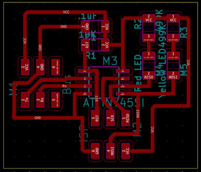
The PCB design is also pretty simple. Again just enough to program the ATtiny45, listen on a network and blink some LEDS.
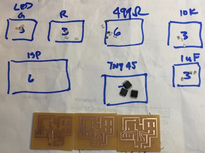
Since this was such a simple PCB, I decided to try to mill this on my CNC. The result, while not perfect, was good enough to create working boards. Here are the boards and parts ready for assembly.
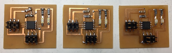
The figure below shows the the boards after coming out of the reflow oven.
The software was written in Arduino C. Each node has a hardcoded ID. The loop reads the serial interface and checks to see if the character on the serial interface matches the ID. If it does both the red and yellow LED are turned on. If not just the red LED is turned on. There is a delay of 1 second to show the result. The following code shows node 1. The same code with the ID replaced with 2, and 3 was loded on the other nodes.
#include >SoftwareSerial.h<

const int ledPin1 = 0;     // GREEN LED
const int ledPin2 =  1;    // RED LED
char ID = '1';
char val;

SoftwareSerial softSerial(4, 3);
void setup() {
  // put your setup code here, to run once:
  softSerial.begin(9600);
    // initialize the LED pins as an output:
  pinMode(ledPin1, OUTPUT);
  pinMode(ledPin2, OUTPUT);

   softSerial.println("I respond to ID: ");
   softSerial.println(ID);
}

void loop() {
  //turn off the LEDS for the next loop
  if (softSerial.available() > 0) {
    val = softSerial.read(); // read the incoming byte:
    softSerial.println(val);

    if (val == ID) {
        digitalWrite(ledPin1,LOW); // turn on the LED when ID matches
        digitalWrite(ledPin2,LOW); // turn on the LED after all reads


    } else {
       digitalWrite(ledPin2,LOW); // turn on the LED after all reads
    }

    delay(1000);
    digitalWrite(ledPin1,HIGH); // turn off the LEDs
    digitalWrite(ledPin2,HIGH);
  }
}
The short video shows the working network. Each node ID is typed on the keyboard and is sent down the the serial interface to all three nodes. The left red LEDs turn on for all nodes that received the message, while both the left red and the right yellow LEDs turn on for the referenced node.