Assignment 12: Applications and Implications
Project Description
Propose a final project masterpiece that integrates the range of units covered
Assignment Details
- Individual assignment:
- Answer the following questions:
- What will it do?
- Who's done what beforehand?
- What will you design?
- What materials and components will be used?
- Where will come from?
- How much will they cost?
- What parts and systems will be made?
- What processes will be used?
- What tasks need to be completed?
- What is the schedule
- How will it be evaluated?
- What other questions need to be asked and answered?
- Your project should incorporate 2D and 3D design, additive and subtractive fabrication processes, electronics design and production, microcontroller interfacing and programming, system integration and packaging
- Where possible, you should make rather than buy the parts of your project
- Projects can be separate or joint, but need to show individual mastery of the skills, and be independently operable
- Answer the following questions:
What will it do?
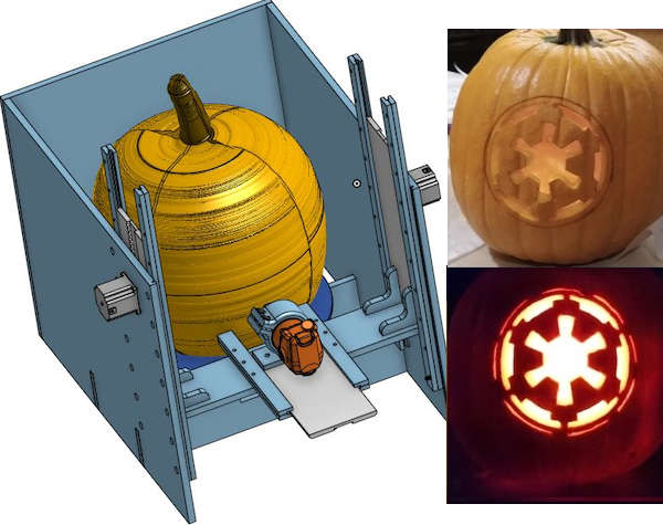
The final project is to create a CNC Lathe that can mill a 2D design onto irregularly shaped sphere (Pumpkin), based on mapping the 2D design onto a point cloud scanned from the target object in four (possibly five) iterations:
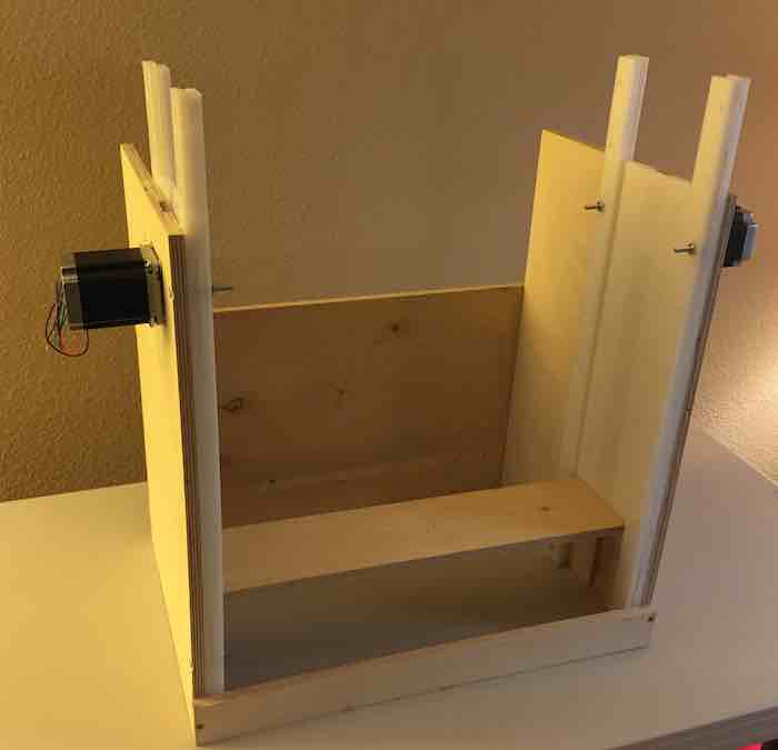
- Iteration 1: Build a vertical oriented CNC lathe
- Iteration 2: Move the steppers based on a jog controller
- Iteration 3: Use the CNC lathe to create a point cloud from probing the target object shape
- Iteration 4: Map a 2D drawing to 3D tool paths (Up/Down, In/Out, Rotation) based on the probed point cloud
- Stretch" goal: Be able to able to vary the cut wall thickness to adjust transmitted light (Lithophane) or create 3D shapes on the pumpkin wall
Who's done what beforehand?
What have I done beforehand?
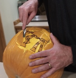
For the past several years, I have used my Laser Cutter/Engraver to etch a drawing onto pumpkins. This requires wearing special eye protection and venting the fumes.
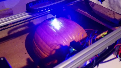
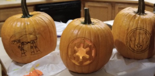
My laser is not strong enough to cut, so the best that it can do is to etch a line. The darkness of the etching varies based on the distance from the laser's focal point. Additional work needs to be done after etching to carve the pumpkin using the etched lines. The goal of the project is to have a "finished" pumpkin when the process completes.
What have others done beforehand?
Here are some previous projects and what applies or does not apply to my problem:
CNCs
- Much of the design is based on the rack and pinion and axis motion from previous year’s CNC designs. There seem to be two schools of thought for the MIT/Fab Academy CNC designs. One led by Jens Dyvik's "Chamfer Rail", uses a rack and pinion with a beveled side sliding in a low friction face to face joint. The other led by Jake Reed, nominally called RCT (Roller Coaster Bearing) uses a timing belt over a toothed pulley to move the gantry back and forth. Roller coaster bearings are used to manage the friction.
- My design leverages the large tooth profile from the rack and pinion design. In previous designs the rack is fixed and the pinch rails move with the gantry. In my design, the pinch rails are fixed and the rack moves with the gantry. Previous application of the rack and pinion designs have been primarily to x, y, z axis CNCs. The Hedy is a vertical mill, but I haven’t seen an application of the concept to a vertical lathe.
- CNC Machine a pumpkin There are a number of documented projects to cut pumpkins with a CNC, but most assume just X, Y, and Z not rotation around an axis and do not account for the irregular shape. Most of these projects do not take into account the actual curvature of the target object in the tool path. These previous approaches may not work for irregular shapes (gourds).
CNC Lathes
- This project extrudes chocolate onto a bananna. Similar idea, but this project needs to cut the object being rotated.
- MIT additive lathe - This is a 3D printer onto a rotating spindle. Maybe able to use ideas for the chuck and rotational gearing, but additive and subtractive processes are different.
- Eggbot - There is an interesting Inkscape plug-in that may provide some ideas to map the 2D shape to 3D shape. The z axis seems to be spring activated touching the surface of the egg. My machine needs to vary the z axis cut depth based on the external shape of the object and how much light is intended to show.
Hardware and Software
This project is highly dependent on previous work on generation of tool paths in G-Code and execution of the G-Code using GRBL and CNC control using Universal G Code Sender (UGS).
- Generation of the initial tool paths from the 2D designs can be done with one of many Open Source G-Code generators such as Easel, Carbide Create, or Kiri:Moto. Each of these programs generate X, Y, Z tool paths that need to be converted to up/down, in/out, and rotation tool paths mapped onto the point cloud of the target object.
- GRBL is a G-Code interpreter that runs on a ATMega 328 type microcontroller. The ATMega 328 board drives a set of stepper motor drivers that move the stepper motors.
- The G-Code is sent to the ATMega 328 by a program running on a PC called Universal G Code Sender (UGS). UGS also has the ability to send individual jog commands or G-Code macros to the microcontroller.
- The point cloud generation is based on execution of a number of G38.2 probe commands in a script that rotates the object and moves the probe to touch points on the outside of the target shape. Each line in the script is issued from UGS and executes a command to move the probe until it touches the target object surface closing a limit switch which completes a circuit and stops the movement. The G-Code coordinates are then passed back from UGS as a set of JSON parameters. These points form the point cloud for the target object.
- The combination of the point cloud and the original G-code are loaded into a program such as G-Code Ripper from http://scorchworks.com which translates the tool paths based on the Point Cloud offsets. This creates the G-Code that is then executed on the target object.
Lithophane (if time remains)
I haven’t found any direct way to generate Lithophane tool paths from a design. Here are some early concepts, that I will explore if I have time.
- This video shows how to create a Lithophane in OpenSCAD.There could be elements that could be reused for 2D to 3D mapping and to determine the wall thickness based on transmitted light.
- This shows an approach to 2D to Cylinder mapping using OpenSCAD. This would have to be adapted from a cylinder to a sphere
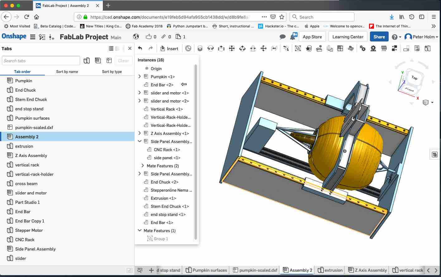
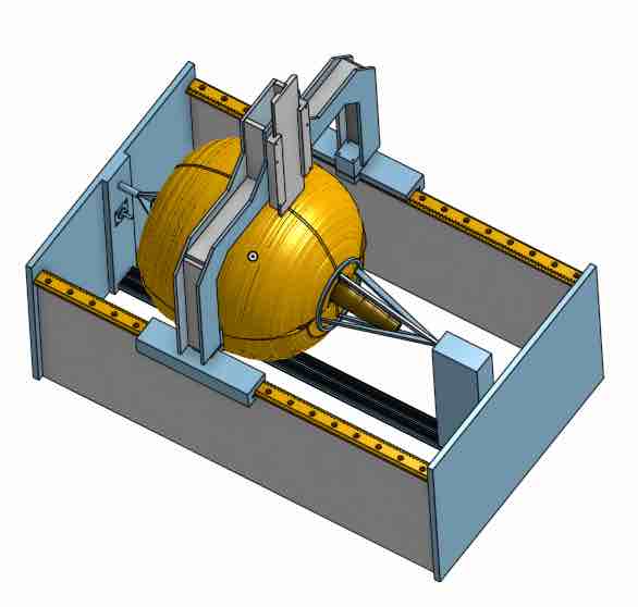
What will you design?
The figure shows a dynamic model of the final project. Move the left mouse button to rotate the assembly. Rotate the mouse button to zoom in or out.
- A mechanism to hold and rotate the irregularly shaped sphere
- Leverage the existing rack and pinion tooth design in up/down and in/out axis gantries
- A mechanism to hold the router on the in/out gantry
- A jog controller to move the steppers
- A sensor probe that travels on the up/down axis and extends on the in/out axis to measure the perimeter of the irregularly shaped sphere
- PCB(s) for the ATMega 328 run GRBL and drive the stepper controllers
- Software to read the depth sensor and create a point model of the perimeter
- Adapt a software tool chain to map the 2D drawing to the 3D sphere and generate the machine commands to cut
Part Assembly Summary Tables
This section is organized by the assemblies that make up the project. The following figures and tables answer the following questions for each assembly:
- What materials and components will be used?
- Where will come from?
- How much will they cost?
- What parts and systems will be made?
- What processes will be used?
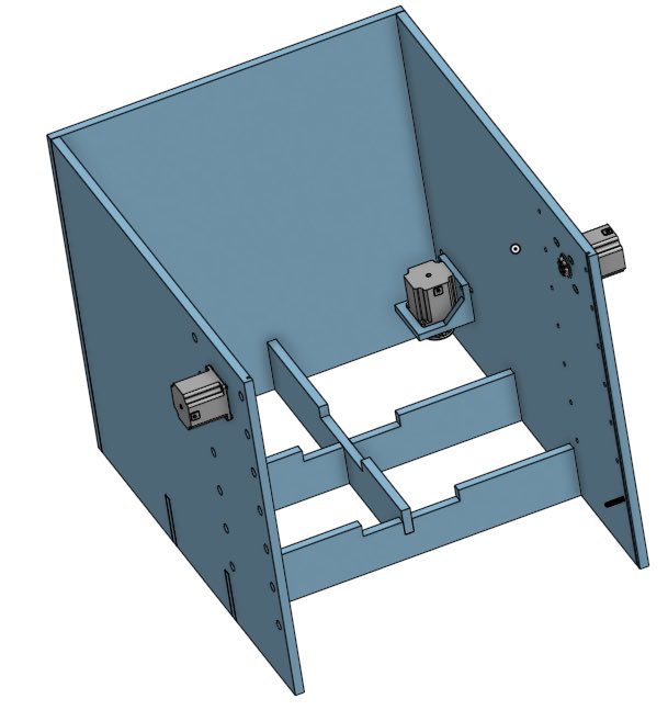
Case Assembly
| Item No. | Name | Quantity | Material | Source | Cost | Make/Buy | Process Used | Reference |
|---|---|---|---|---|---|---|---|---|
| 1 | Case Assembly | http://www.crosscuthardwoods.com/ | ||||||
| 1.1 | Case - Right Side | 1 | 1/2” Plywood | Crosscut Hardwoods | *1 | Make | Large CNC | http://www.crosscuthardwoods.com/ |
| 1.2 | Case - Left Side | 1 | 1/2” Plywood | Crosscut Hardwoods | *1 | Make | Large CNC | http://www.crosscuthardwoods.com/ |
| 1.3 | Case - Back Side | 1 | 1/2” Plywood | Crosscut Hardwoods | *1 | Make | Large CNC | http://www.crosscuthardwoods.com/ |
| 1.4 | Case - bottom support | 2 | 1/2” Plywood | Crosscut Hardwoods | *1 | Make | Large CNC | http://www.crosscuthardwoods.com/ |
| 1.5 | Case - cross support | 1 | 1/2” Plywood | Crosscut Hardwoods | *1 | Make | Large CNC | http://www.crosscuthardwoods.com/ |
| 1.6 | rotating axis motor bracket | 1 | PLA Filliment | *2 | Make | 3D Print | ||
| 1.7 | large pinion 60 circ v2 | 2 | 1/2” HPDE | Tap Plastics | *3 | Small CNC | https://www.tapplastics.com/product/plastics/cut_to_size_plastic/hdpe_cutting_boards/346 | |
| 1.8 | NEMA23 Stepper - 270 in-oz (57BYGHH627) | 3 | Wantai Motor - eBay via Makerspace Order | $20 / ea | Buy |
*1 - 5' x 5' Russian Birch Plywood - $50. *2 - PLA 3D Printer filament - $20 *3 - 6" x 6" x .5" HPDE - $10
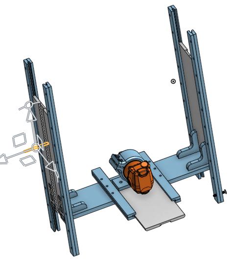
Gantry Assembly
| Item No. | Name | Quantity | Material | Source | Cost | Make/Buy | Process Used | Reference |
|---|---|---|---|---|---|---|---|---|
| 2 | Gantry Assembly | |||||||
| 2.1 | Up/Down Rack Assembly | 1 | Make | Large CNC | ||||
| 2.1.1 | innerRailBrace | 4 | 3/8” HPDE | Tap Plastics | *4 | Make | Large CNC | https://www.tapplastics.com/product/plastics/cut_to_size_plastic/hdpe_sheets/529 |
| 2.1.2 | outerRailBrace | 4 | 3/8” HPDE | Tap Plastics | *4 | Make | Large CNC | https://www.tapplastics.com/product/plastics/cut_to_size_plastic/hdpe_sheets/529 |
| 2.1.3 | 15.5 in Rack - Right | 1 | 3/8” HPDE | Tap Plastics | *4 | Make | Large CNC | https://www.tapplastics.com/product/plastics/cut_to_size_plastic/hdpe_sheets/529 |
| 2.1.4 | 15.5 Rack - Left | 1 | 3/8” HPDE | Tap Plastics | *4 | Make | Large CNC | https://www.tapplastics.com/product/plastics/cut_to_size_plastic/hdpe_sheets/529 |
| 2.2 | Gantry Cross Bracket | 1 | 1/2” Plywood | Crosscut Hardwoods | *1 | Make | Large CNC | http://www.crosscuthardwoods.com/ |
| 2.3 | Corner Bracket | 4 | 1/2” Plywood | Crosscut Hardwoods | *1 | Make | Large CNC | http://www.crosscuthardwoods.com/ |
| 2.4 | In/Out Rack Assembly | 1 | ||||||
| 2.4.1 | left - short inner brace | 1 | 3/8” HPDE | Tap Plastics | *4 | Make | Large CNC | https://www.tapplastics.com/product/plastics/cut_to_size_plastic/hdpe_sheets/529 |
| 2.4.2 | left - short outer brace | 1 | 3/8” HPDE | Tap Plastics | *4 | Make | Large CNC | https://www.tapplastics.com/product/plastics/cut_to_size_plastic/hdpe_sheets/529 |
| 2.4.3 | right - short outer brace | 1 | 3/8” HPDE | Tap Plastics | *4 | Make | Large CNC | https://www.tapplastics.com/product/plastics/cut_to_size_plastic/hdpe_sheets/529 |
| 2.4.4 | right- short inner brace | 1 | 3/8” HPDE | Tap Plastics | *4 | Make | Large CNC | https://www.tapplastics.com/product/plastics/cut_to_size_plastic/hdpe_sheets/529 |
| 2.4.5 | 11 in Rack | 1 | 3/8” HPDE | Tap Plastics | *4 | Make | Large CNC | https://www.tapplastics.com/product/plastics/cut_to_size_plastic/hdpe_sheets/529 |
| 2.4.6 | Router Bracket | 1 | PLA Filliment | Make | 3D Print | |||
| 2.4.7 | NEMA23 Stepper - 270 in-oz (57BYGHH627) | 1 | Wantai Motor - eBay | $20 / ea | Buy |
*4 - 2" x 3" x .375" HPDE - $60
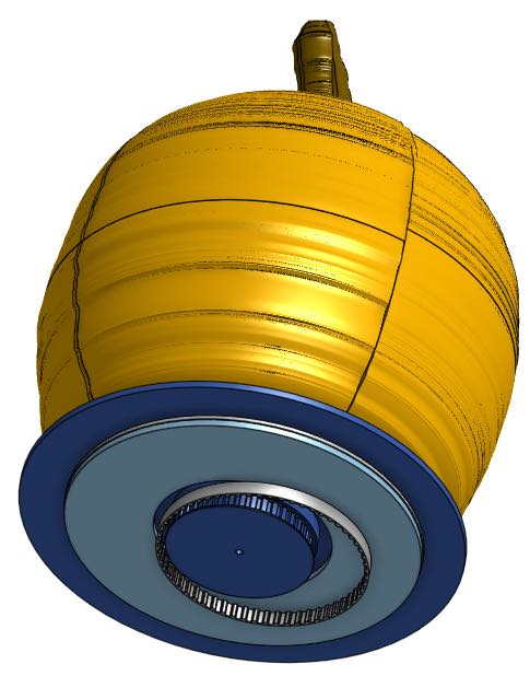
Rotating Axis Base Assembly
| Item No. | Name | Quantity | Material | Source | Cost | Make/Buy | Process Used | Reference |
|---|---|---|---|---|---|---|---|---|
| 3 | Rotating Axis Base Assembly | 1 | ||||||
| 3.1 | Lazy Susan Mount | 1 | 1/2” Plywood | Crosscut Hardwoods | *1 | Make | Large CNC | http://www.crosscuthardwoods.com/ |
| 3.2 | Rotating Base | 1 | 1/2” Plywood | Crosscut Hardwoods | *1 | Make | Large CNC | http://www.crosscuthardwoods.com/ |
| 3.3 | "12"" Round Lazy Susan - 28985" | Rockler Woodworking and Hardware | $10.00 | Buy | ||||
| 3.4 | "1/2” Wd. .375 Pitch, L Series Timing Belt" | 1 | $15.00 | Buy | https://www.mcmaster.com/timing-belts |
Probe Assembly
| Item No. | Name | Quantity | Material | Source | Cost | Make/Buy | Process Used | Reference |
|---|---|---|---|---|---|---|---|---|
| 4 | Probe Assembly | |||||||
| 4.1 | Probe Housing | PLA Filliment | *2 | Make | 3D Print | |||
| 4.2 | Probe | 1/16 Metal Rod | Buy | |||||
| 4.3 | Limit Switch | Scrap Materials from Makerspace | Free | Acquire |
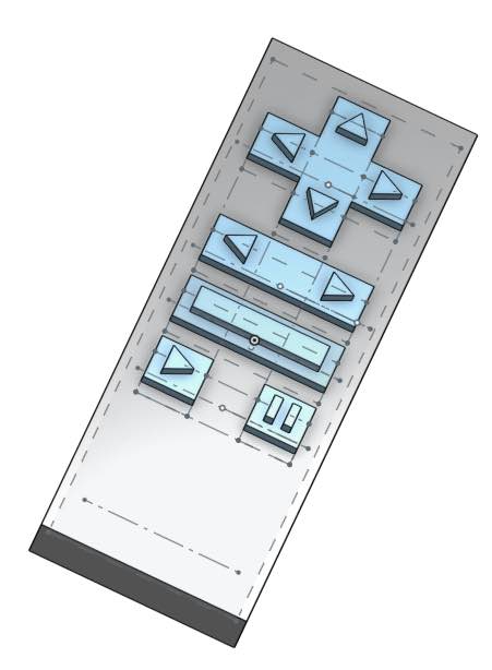
Jog Controller Assembly
| Item No. | Name | Quantity | Material | Source | Cost | Make/Buy | Process Used | Reference |
|---|---|---|---|---|---|---|---|---|
| 5 | Jog Controller Assembly | |||||||
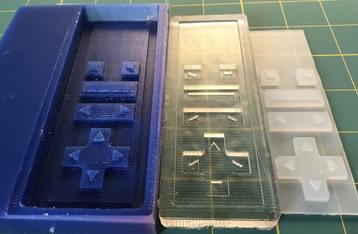
| 5.1 | Silicone button casting | Free | Acquire | |||||
| 5.2 | Jog Controller PCB | Make | PCB CNC | |||||
| 5.3 | Jog Controller Case | 3/8” HPDE | Tap Plastics | *4 | Make | Small CNC |
Electronics
| Item No. | Name | Quantity | Material | Source | Cost | Make/Buy | Process Used | Reference |
|---|---|---|---|---|---|---|---|---|
| 6 | Electronics | |||||||
| 6.1 | 24v 15a DC Universal Regulated Switching Power Supply | EAGWELL (amazon.com) | $24.68 | Buy | https://www.amazon.com/EAGWELL-Universal-Regulated-Switching-Computer/dp/B01IOK5FM0/ref=cm_cr_arp_d_product_top?ie=UTF8 | |||
| 6.2 | PCB Assembly | |||||||
| 6.2.1 | GRBL board | Make | PCB CNC | |||||
| 6.2.2 | Stepper Motor driver shield | Make | PCB CNC | |||||
| 6.2.3 | DRV 8255 - Stepper Motor Driver | Scrap Materials from Makerspace | Acquire |
What tasks need to be completed and when are they scheduled?
Here are the iterations and specific tasks within each iteration:
| Iteration | Task Name | Status | Scheduled Completion | ||
|---|---|---|---|---|---|
| Build a vertical oriented CNC lathe | In-Work | ||||
| Fabricate Case Assembly | Complete | 4/23 | |||
| Fabricate Rotating Axis Base Assembly | Designed | 4/24 | |||
| Fabricate Gantry Assembly | Designed | 5/2 | |||
| Fabricate ATMega 328 board and stepper driver shield | Investigating design | 5/10 | |||
| Load GRBL on Board | 5/15 | ||||
| Integrate with UGS and calibrate distance coordinates | 5/15 | ||||
| Move the steppers based on a jog controller | |||||
| Mold silicone button pad | Complete | 2/20 | |||
| Mill jog controller housing | Designed | 5/3 | |||
| Fabricate Jog Controller PCB | Complete | 4/18 | |||
| Write integration SW and test with UGS REST server | Conceptual Design | 5/15 | |||
| Use the CNC lathe to create a point cloud from probing the target object shape | |||||
| Fabricate Probe Assembly | Conceptual Design | 5/3 | |||
| Integrate and test G28.2 command | 5/15 | ||||
| Write script to execute probe commands create point cloud file | 5/17 | ||||
| Map a 2D drawing to 3D tool paths (Up/Down | In/Out | Rotation) based on the probed point cloud | |||
| Integrate point cloud file and shape g-code file with G-Code Ripper | 5/24 |
How will it be evaluated?
Will my wife allow me to put pumpkins created by the CNC on the front porch?
What other questions need to be asked and answered?
I am continually learning new things. Just when I think that I know everything, I find something that I didn't consider. As a result, I have learned that the thing that I don't know or the question that I haven't asked is the one that gets me into trouble.
The answer to the question: "What other questions need to be asked and answered" is the one that I haven't asked.
Related Projects