Assignment 5: 3D Scanning and Printing
Project Description
Explore 3D scanning and printing
Assignment Details
- Group Assignment:
- Test the design rules for your 3D printer(s)
- Individual assignment:
- Design and 3D print an object (small, few cm3, limited by printer time) that could not be made subtractively
- 3D scan an object (and optionally print it)
Scan Something - Photogrammetry
I have not done any 3D scanning in the past. To get up to speed on the subject I completed the following Lynda classes:
After completing the classes, I signed up for a AutoDesck account and downloaded a trial version of AutoDesk ReCap and ReCap Photo applications. These don't run on my Mac, so I found an older PC to host the apps.
The goal of the first activity was to use Photogrammetry to create a 3D model of a small plastic toy.
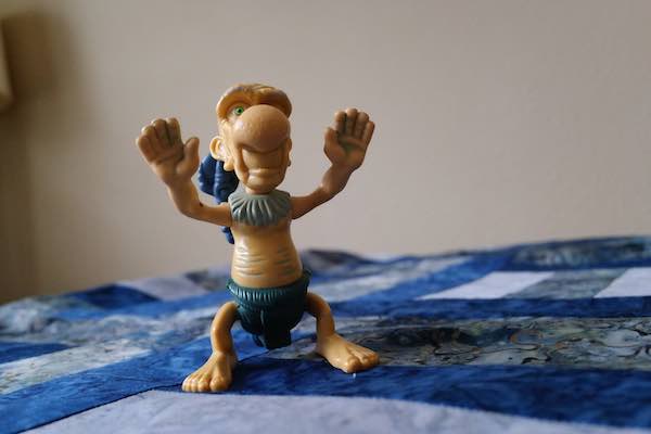
Photogrammetry is based on blending a large number of static pictures of the same object from different perspectives into one 3D model. The Lynda class recommended that the object be placed on a surface with a pattern. In this case I used one of my wife's quilts as the base.
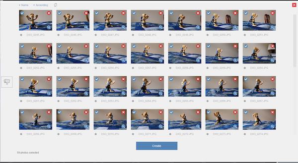
I took 51 pictures of the toy at about 5 degree increments around the object and at various vertical angles. These pictures were used as the input to the AutoDesk ReCap Photo application.
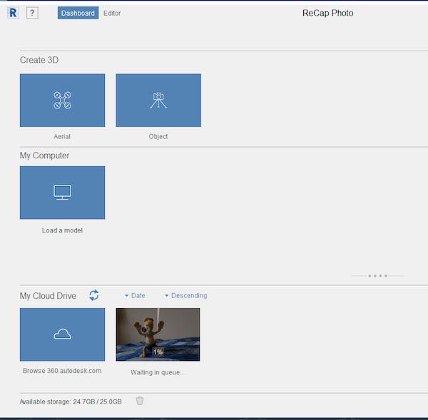
AutoDesk ReCap Photo is a desktop app, but the real work happens in the cloud. The next step was to upload all the pictures using the app to AutoDesk's server and queue the job. The job showed "Waiting in Queue..." after the upload. Many hours later, the job completed and I was able to download the completed 3D model.
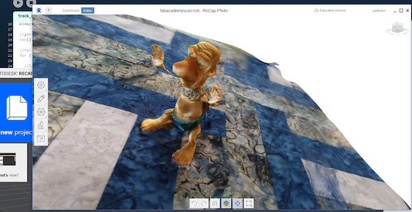
The model came back and looked pretty good. I must not have gotten enough pictures of one of the arms, because there was a gap from the body to the arm on the left side. Because of the many hours waiting for the scan to come back I decided to work with this model rather that taking more pictures, re-submitting and waiting many more hours.
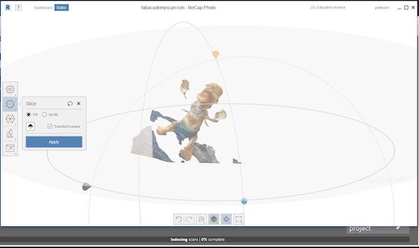
The Lynda class suggested that the pattern base should be removed to leave just the shape. I used the ReCap Picture editing tools to select and remove sections of the base until just the object remained.
Scan Something - Kinect Sensor
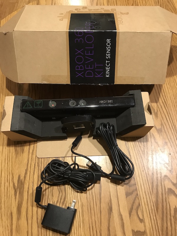
I looked at the other types of scanning programs and they all required some type of scanner. I starting looking around for an inexpensive scanner. After some searching, I discovered that used Microsoft Kinect scanners, if found, could be fairly inexpensive. To meet the tight schedule of the class, I needed to find something local. After more searching, I found a model V1 model 1414 at a used computer store. I brought one home late on Friday and didn't look up from the computer until Tuesday morning. Looking at it now, the scans show that I may have been too focused.
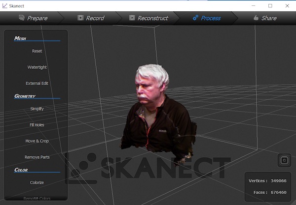
I plugged the Kinect into my Mac and it showed up as a USB device. When I tried to access it from applications, the apps couldn't see it. After some research, some MacBook Air's don't have enough power in the USB port to power the Kinect. Rather than trying to debug this problem, I went back to the old PC. First I downloaded the Scannect app. I was able to get a head and upper chest scan with the Kinect. I found that leveraging the nVidia GPU made the program much more responsive. 360 degree scanning was very slow and error prone. Eventually I got a scan that was acceptable. I edited the model to fill holes and cropped the bottom of the model. After completing the scan and editing, my model used about 350K vertices and 676K faces. I found that the free version of the app would only export 5k faces to an STL file. As a result the exported file lost most of the detail, so the search for scanning apps continued.
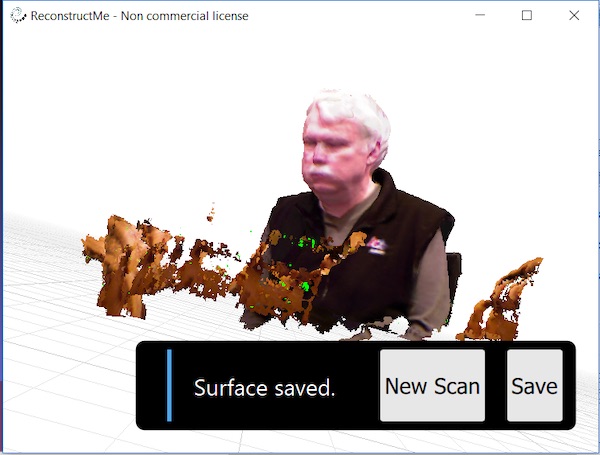
The search led next to the Reconstruct-me app. The app had a similar workflow to capture a 360 scan. More important, it's non-commercial license didn't limit the number of vertices and faces, so the next step was to export an STL file.
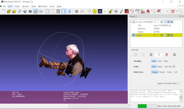
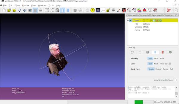
The Reconstruct-me scan included some background that I wanted to remove. MeshLab app was the recommended app to edit models. I downloaded and installed the app. Next I used the app to cut the unwanted areas of the model.
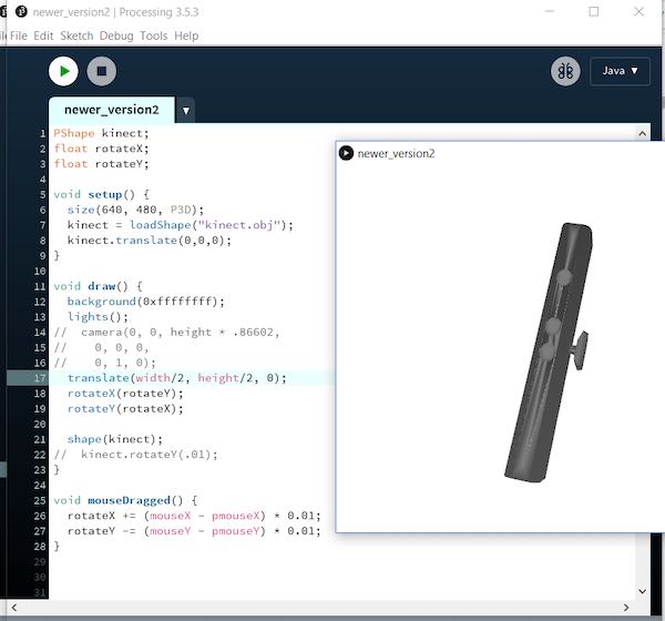
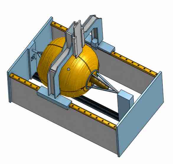
Next I jumped into the rabbit hole by working through the examples in the book “Making Things See”, by Greg Borenstein. The book shows how to use the Processing scripting environment to create applications that leverage the Kinect. My background as a software developer led me to want to dive into how the Kinect worked. I also wanted to understand how to write my own scanning programs. The figure above, shows the first step to write a program to open a 3D model and navigate through it with a mouse. (This was quite easy in Processing.) The program imported a model of a Kinect. The mouse could be used to spin the model.
The Processing environment leverages a library called SimpleOpenNI which provides a wrapper on top of the OpenNI API. OpenNI was created by PrimeSense, who developed the technology that underlies the Kinect.
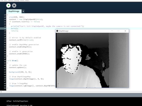
I learned that the the Kinect contained distance and RGB cameras. The distance camera looks at infrared dots that are projected on objects in front the Kinect. Differences in where the dots appear is used by the Kinect to build any arrary of distance pixels. The first example simply displayed the information from the depth camera.
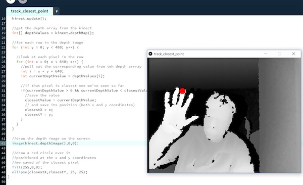
Before I got to the chapter that covered scanning, there were several chapters that provided examples for using the distance sensor as an input to a program. I know that the sensor input lecture is coming up, so I decided to get a head start and work through some examples this week. This one shows using the closest point to draw a point on the screen. Later examples show how to build a 3D drawing program using your hand as an input. Another example showed how to build a "Minority Report" like app to move images around in space.
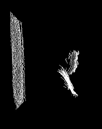
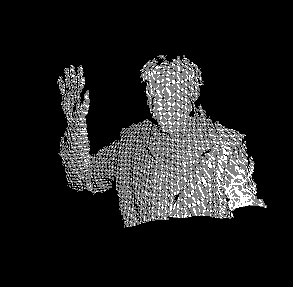
Finally I got to the chapter that covered building point cloud models. This shows both my profile and the points reflecting off the wall behind me.
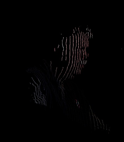
The figure above shows the result of combining the RGB camera results with the point camera. The distance camera was used to determine the location of the point and the RGB camera was used to determine the color of the point. This combination was what the other scanning programs used in their 360 scans.
The key to converting point clouds into STL models is the generation of triangles. This program looped through the distance camera array and built triangles based on the surrounding cells with an offset. Generation of triangles where the points are similar in distance is easy. The hard part is knowing how to deal with edge conditions such as point shadows and other places where the distance array contains "0" values. The example in the book didn't work when I tried it, so I rewrote the example and spent a little time looking at making it better. I ran out of time, so the "easy" part looks good, but the edges still are rough.
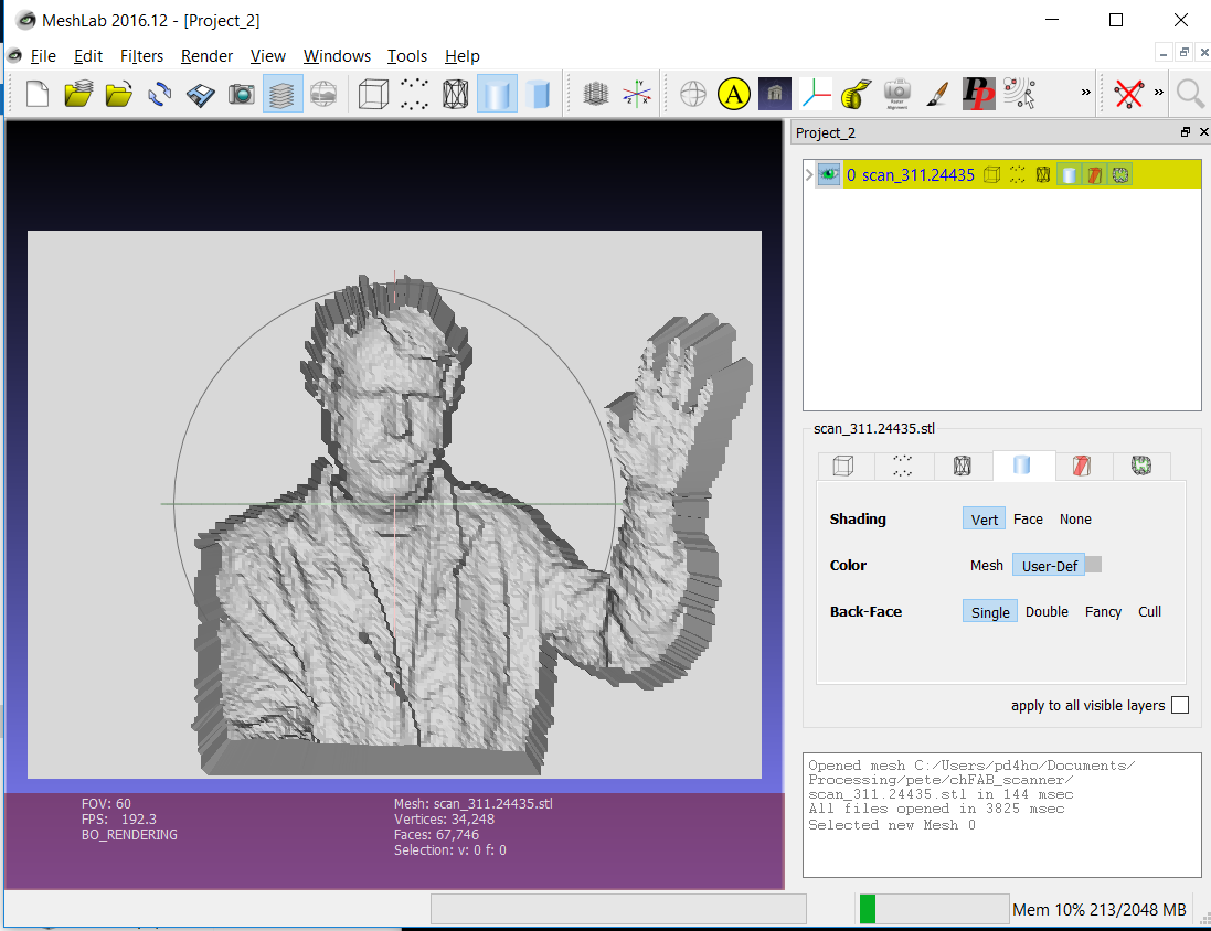
The script was able to build the triangles and export a STL file. Next I imported the STL into MeshLab. The figure above shows where more could be done on the edges. At this point I needed to move on to complete the 3D printing assignments.
I am considering using the Kinect as an alternative way to scan the pumpkin in my Final Project. If nothing else, the ideas used in the Processing script could be used with a physical touch probe to create a distance array (similar to the Kinect) and then use surrounding points to generate the triangles to generate an STL file. The STL file could then be the input to MeshLab or Blender and used as the basis for sculpting the pumpkin.
Test the design rules for your 3D printer(s)
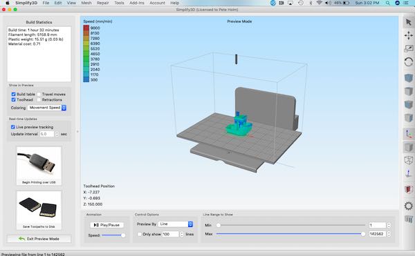
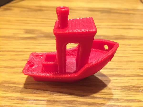
One of the most popular 3D Printer validation models appears to be the 3D-Benchy. The model is a boat with several hard to build features. The bow of the boat has slopes that can be challenging. The other pieces are set to specific dimensions that can be validated after the print. The figure above shows the 3D-Benchy model in the Simplify3D application. I use Simplify3D as the slicing program which generates G-Code from the STL file. The printer uses the G-Code to print the model.
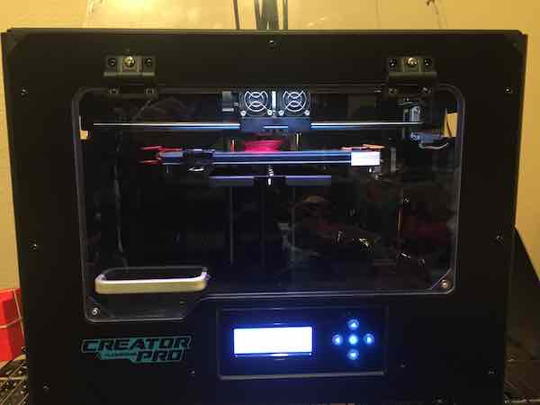
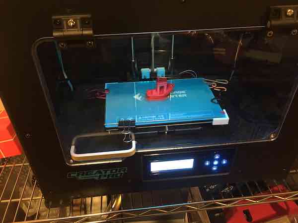
The figures above show my Source Forge Creator Pro 3D printer. The first figure shows printing the 3D-Benchy. The second figure shows the completed print.
The SourceForge printer did a good job on the final 3D-Benchy. I am using the printer settings recommended by the Simplify3D program with a few changes.
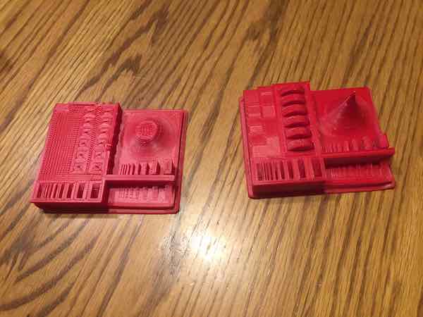
The figure above shows 2 prints of the test part from Neil's lecture. The slicing program cut off the top of the pointed structure. The first print stopped halfway through (a frequent problem). The second print completed and did a pretty good job.
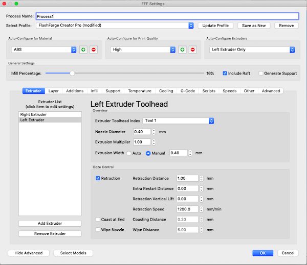
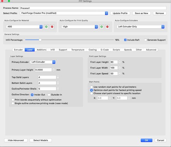
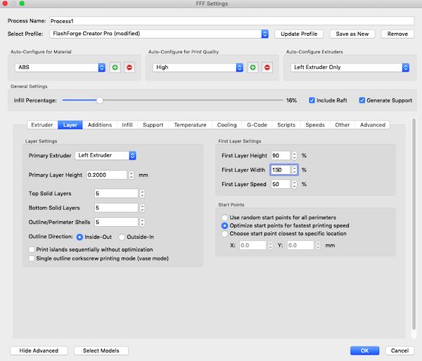
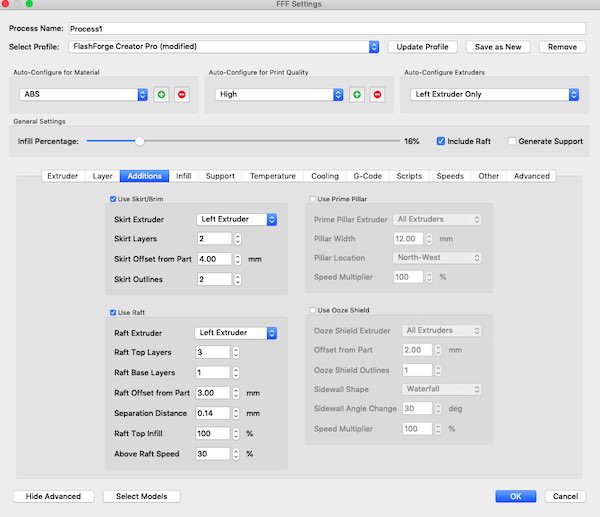
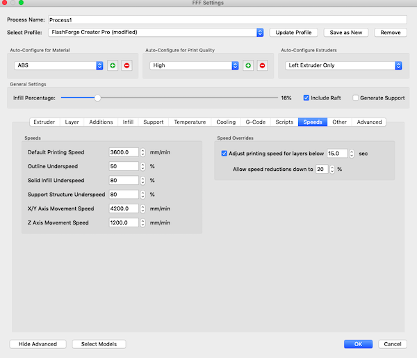
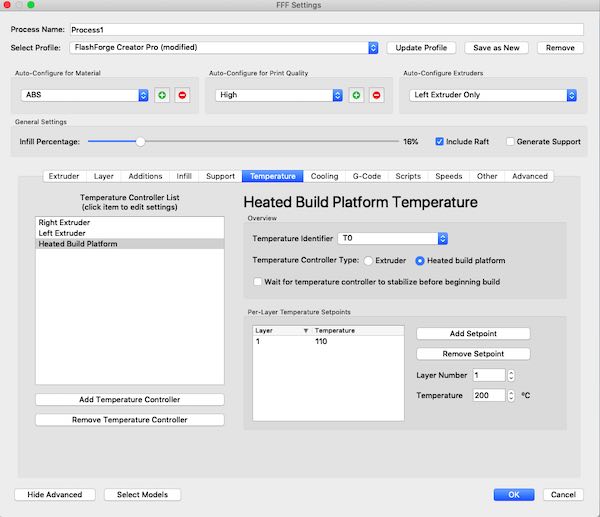
The figures above show the settings that were used in the test prints.
Design and 3D print an object that could not be made subtractively
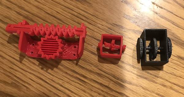
The three prints show attempts to print something that cannot be made subtractively. The print on the left came from Thinkiverse and was an attempt to try example of printing a gear box in place. The resulting print stopped half way through, but more important, the two gears were printed fixed to the gear box frame. This meant that the gears could not rotate. When I made my own model in OnShape, I decided to simplify the design. My model only has one axle with three rotating disks, so it printed much faster. This shows the concept of printing parts in context. The middle print shows a smaller failed print. Starting with a smaller model meant that the design was more sensitive to the layer thickness. The combination of small size and layer thickness led to a failed print. The shaft did rotate. the print on the right shows the result after I went back and increased the size of the print. I also printed this one on a library computer. The end result successfully rotated on the axle as planned. If this was built subtractively, the gear box would need to have the hole drilled, then the axle inserted and then the disks would need to be attached. In this case everything was printed in one step.
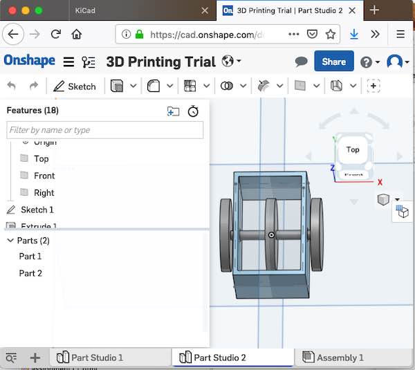
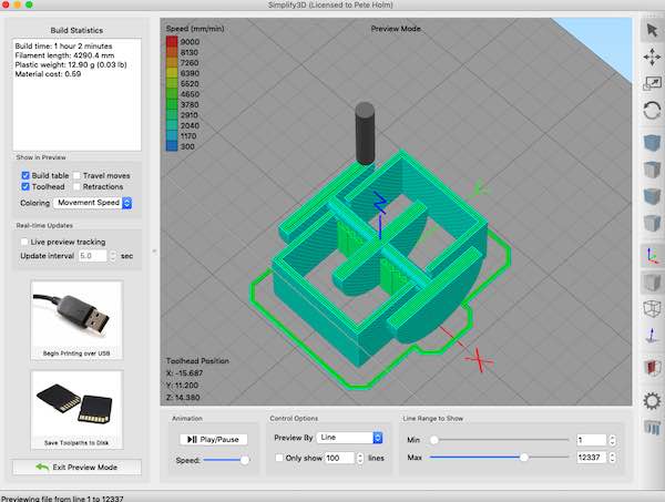
The figures below show the CAD model and half way thorugh the Simplify3D slicing model. The slicing model shows how a gap was left between the the gear box hole and the axle with the disks. This allowed the "print in place" parts to rotate.
Reference Files
Related Projects