Assignment 2: Computer Aided Design
Project Description
Investigate several CAD / Modeling Tools
Assignment Details
- Model (raster, vector, 2D, 3D, render, animate, simulate, ...) a possible final project
- Post it on your class page
Background
Many years ago, I took a Boeing class that taught a early version of Catia. Since then I have not much with CAD tooling. My FIRST robotics kids are using OnShape, so I decided to first start learning about OnShape and then learn about as many other CAD tools as would fit. I spent 2 days looking at FreeCAD. I wanted to look at Fusion360, but ran out of time. I use Inkscape to create designs to Laser cut, so I had some experience. I am new to GIMP, but decided to spend my time in the CAD tooling rather than Photo Editors. The first section covers work in FreeCAD, the second section covers use of Gimp, Inkscape and OnShape to create the CAD model for the CNC Pumpkin Lathe final project. A key design consideration was to support irregular non-spheres. Using a real pumpkin profile broken into sections was the key to simulating digitally simulating a pumpkin. The second section shows the steps to reach this goal.
Summary of Week - Created this CAD Model
Source of Training
Our local library provides access to the lynda.com training site. The site provides an outstanding source of bite sized training on many subjects. Here is a list of the videos and classes that I watched:,
Learned about FreeCAD from these tutorials
- Creating a simple part with PartDesign
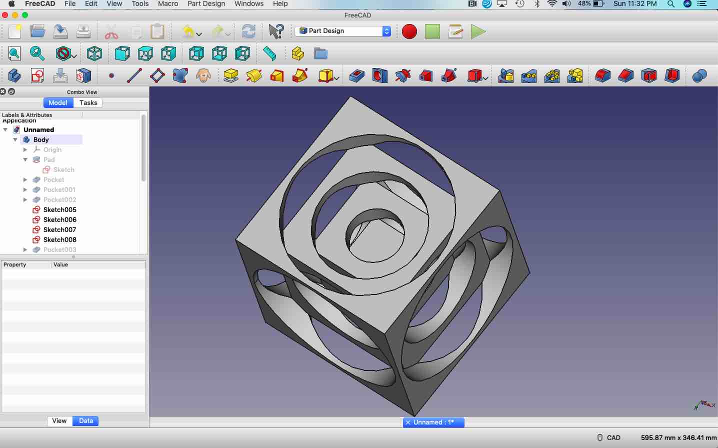
- FreeCAD Lesson 01 - Turners Cube
- Wanted more background on FreeCAD, so downloaded the .pdf version of “FREECAD a Manual” by York Van Havre and the FREECAD COMMUNITY
Note on Screen Shots
To reduce Git storage, I selectively included screen shots that show examples of progress.
FreeCAD Training
As mentioned earlier, there was a desire to look at more than one CAD tool this week. Worked through the examples in the FreeCAD Manual referenced earlier. Here is a summary of what was learned. FreeCAD is organized by WorkBenches. Each Workbench is a way to group commands that could be used to perform an activity. The examples were grouped by workbench.
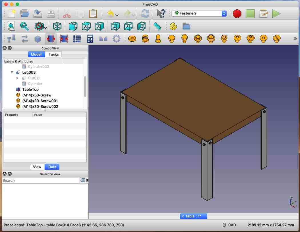
- Part Workbench Tutorial - Create a table with legs and fasteners with basic shapes and build Turners Cube
- Learned how to use hidden shapes to cut from visible shapes
- Learned how to to add an add-on, in this case Fasteners. Fasteners shows up as an additional workbench - makes it easy to add bolts for holes in a model
- Learned how to to geometric operations to remove extrusions
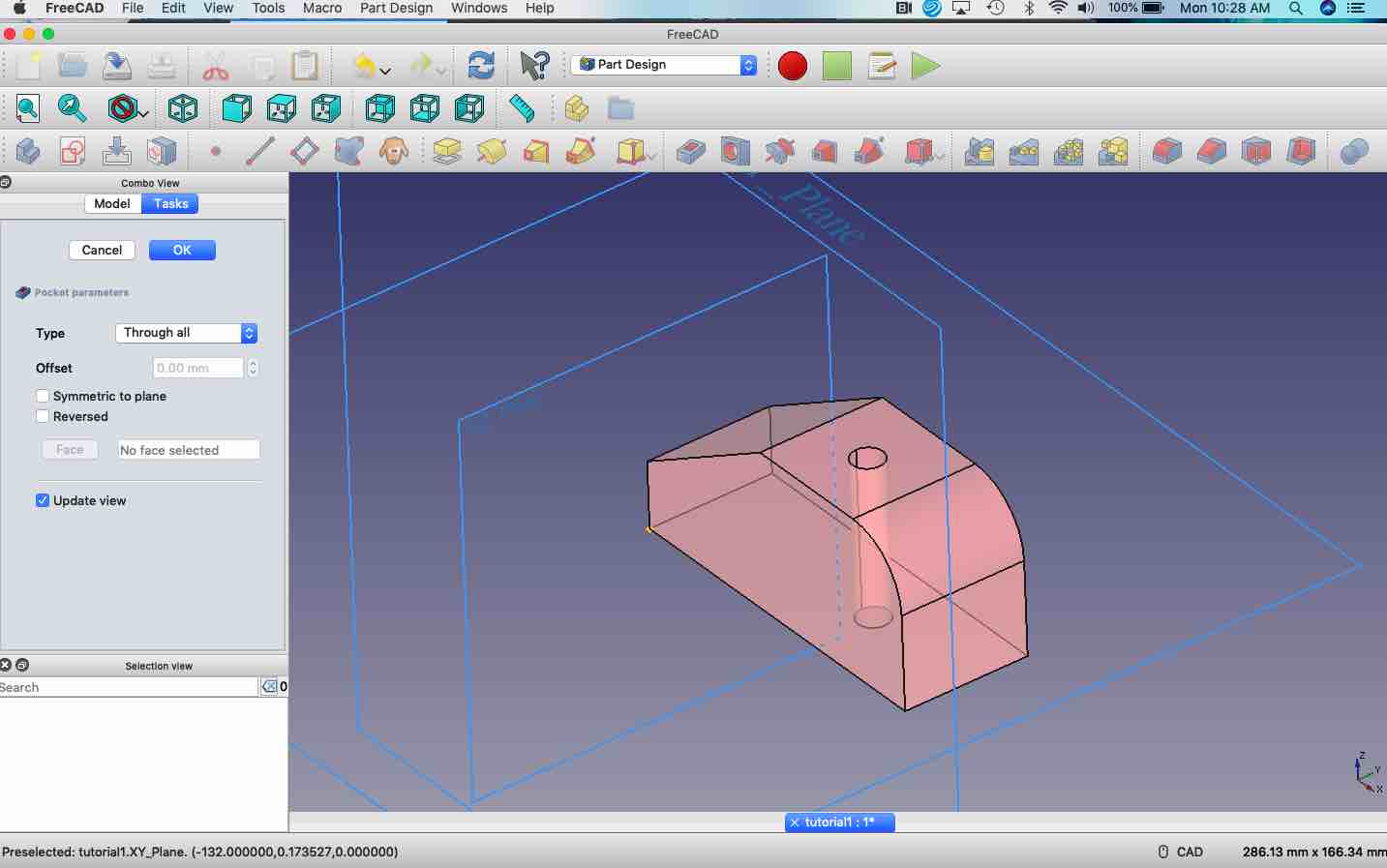
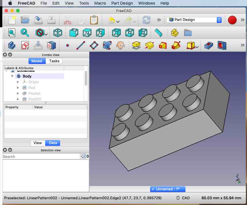
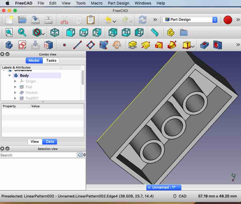
- Part Design Workbench Tutorial - Create a part with a hole and a Lego block using extrude commands
- Learned how to use the sketch tool to create and extrude a part
- Learned how to use linear pattern tool to repeat geometric shapes
- Learned how to use the sketch tool to create and extrude a part
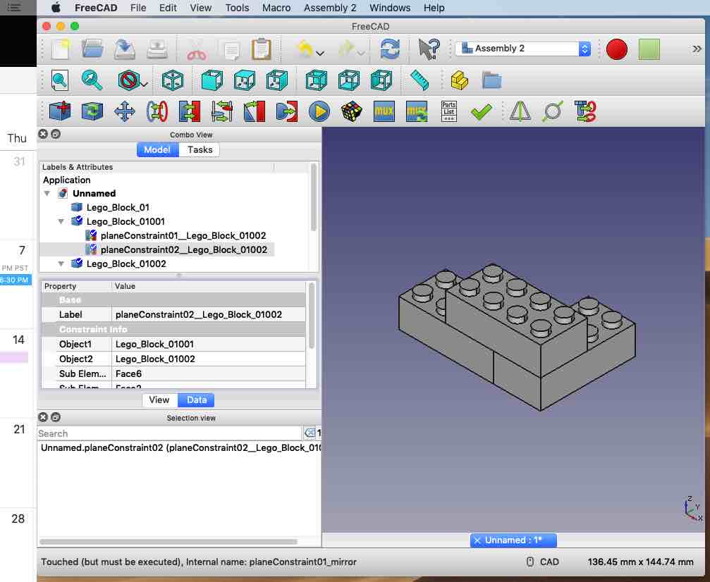
- Assembly2 add-on Workbench Tutorial - Create assemblies of parts
- Learned how to use contraints to join parts - This worked for simple joins, but generated errors when several parts were involved. Don't know if this was my lack of knowledge or a bug in the tooling. Did some Googling and found a newer version of a workbench that also does assemblies. Used this workbench without errors.
- Learned how to use contraints to join parts - This worked for simple joins, but generated errors when several parts were involved. Don't know if this was my lack of knowledge or a bug in the tooling. Did some Googling and found a newer version of a workbench that also does assemblies. Used this workbench without errors.
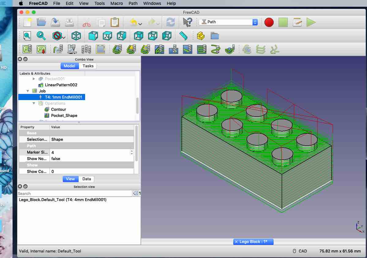
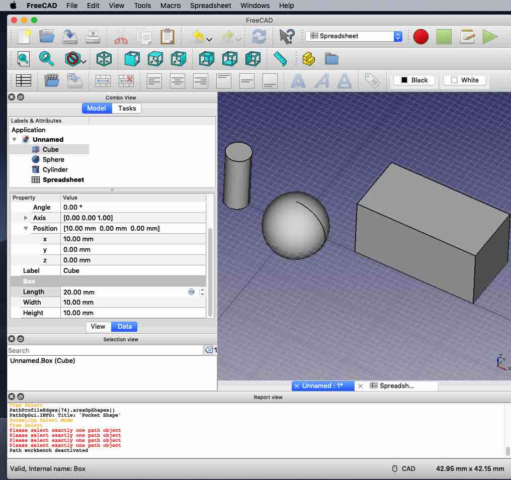
- Path Workbench Tutorial - Create G-Code
- Learned how to generate and simulate G-Code paths that could be used in a CNC to cut a part. I did not have enough time to try out the G-Code in on a CNC.
- Learned how to generate and simulate G-Code paths that could be used in a CNC to cut a part. I did not have enough time to try out the G-Code in on a CNC.
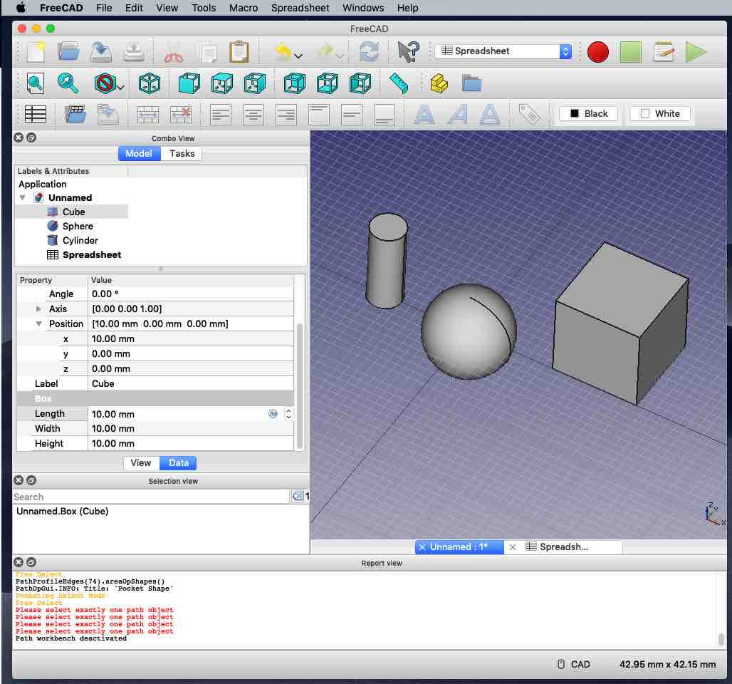
- Spreadsheet Workbench Tutorial - Create Parameteric Attributes
- FreeCAD does not support circular dependencies, so a spreadsheet can only be used to set values or display values in a part
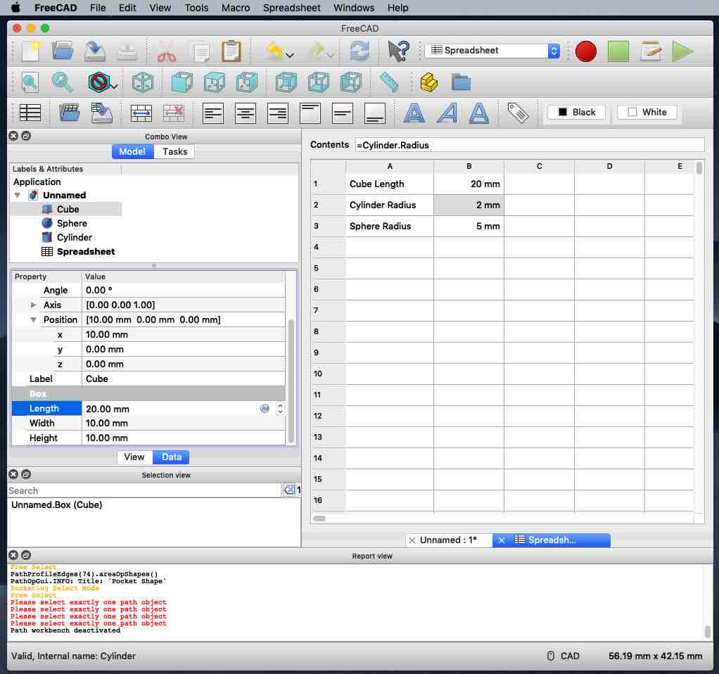
- Learned how to create a spreadsheet that displays the current values of selected part attributes
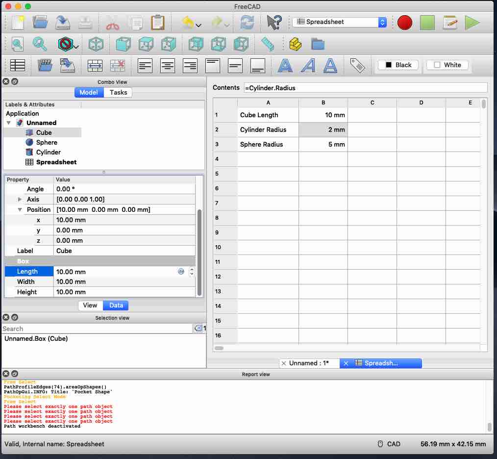
- Moved on to create a spreadsheet that sets values of selected part attributes. Found a possible bug in using a spreadsheet to set an attribute - after setting the alias reference in an object attribute setting, clicking on “done” doesn’t set the value, only clicking “enter” sets the value. Updating the spreadsheet only updates the spreadsheet value when the value dialog was closed by pressing “enter”
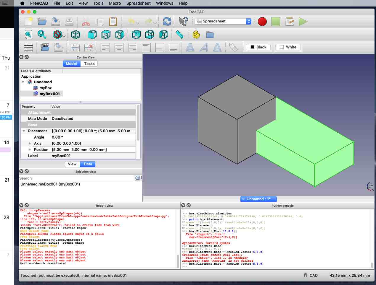
- Python Console - Perform FeeCad commands using Python scripts
- Learned how to create a new document
- Learned how to create new boxes
- Learned how to change the size and position of the boxes
Using Gimp, Inkscape, and OnShape to generate a CAD Model of the CNC Pumpkin Lathe
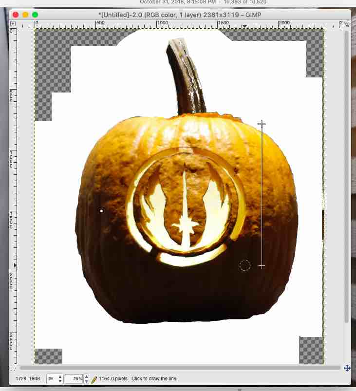
The first problem that I ran into was determining the size of the lathe. Couldn't find any pumpkins, this time of year, so I decided to use Gimp and Inkscape to convert a picture of last years pumpkin into a vector drawing that I could upload to OnShape.
I started with by cutting an image of the pumpkin using Gimp.

Next, the color of the pumpkin was used to generate 2 bit image of the pumpkin
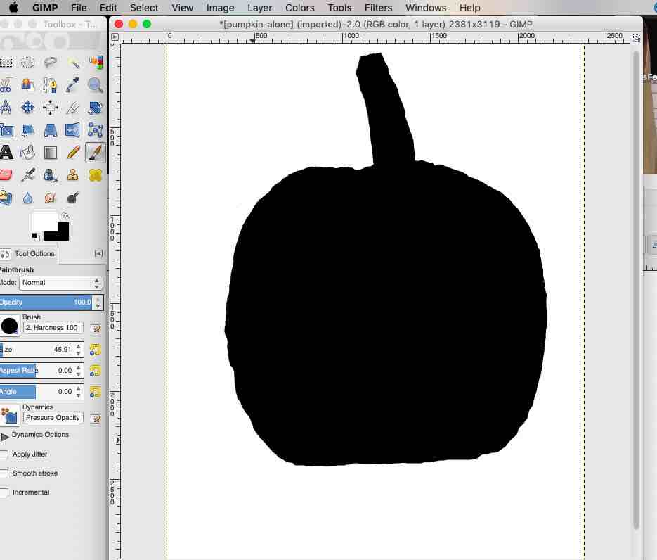
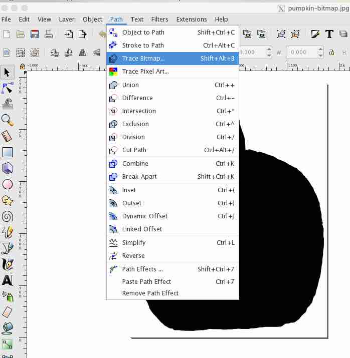
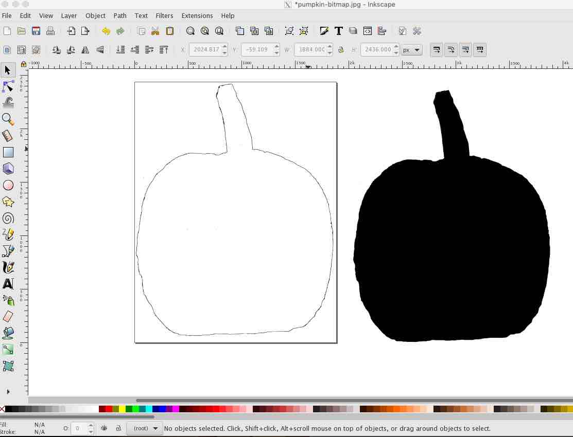
The bitmap was imported into Inkscape and then converted into a vector drawing
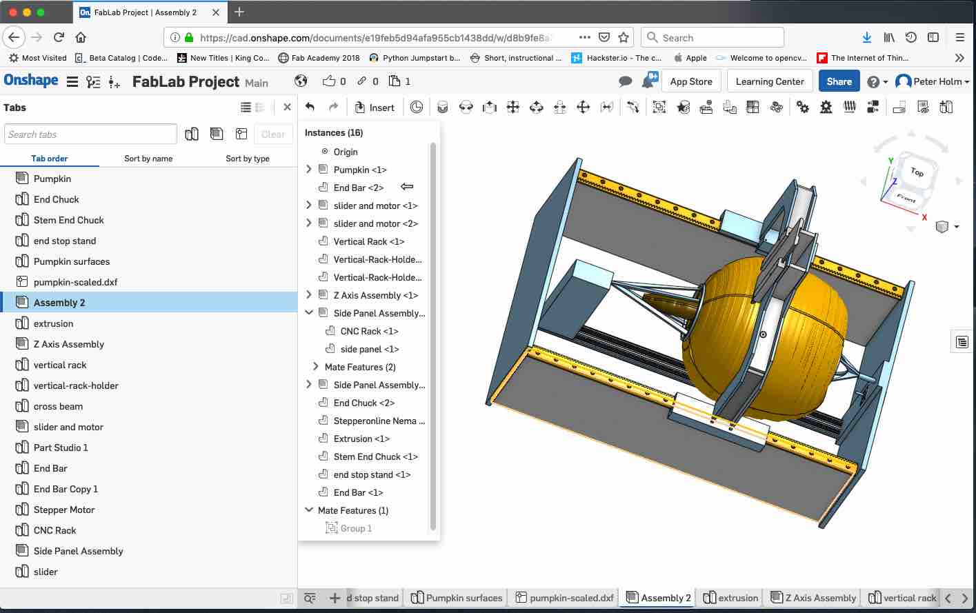
The vector was exported as a DXF and then imported into OnShape. I used the diameter of the bucket that the pumpkin was sitting on as a reference to size the pumpkin.
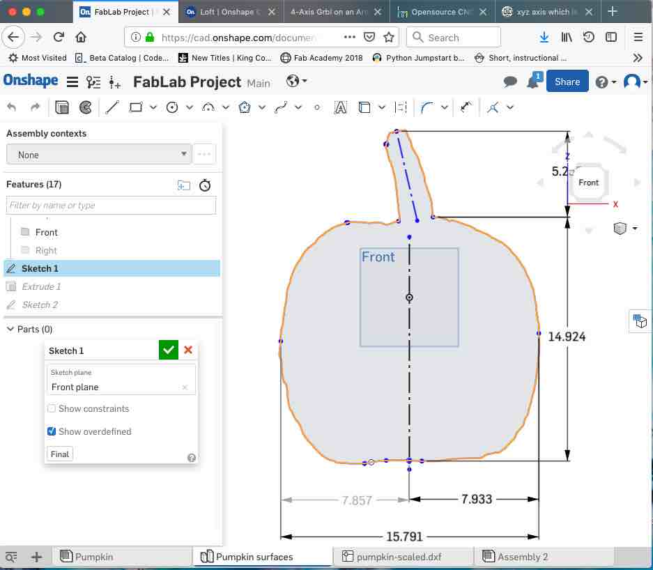
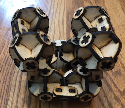
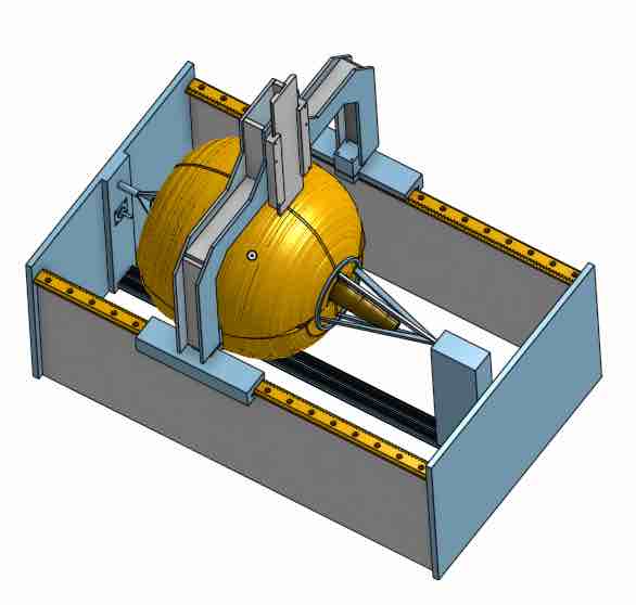
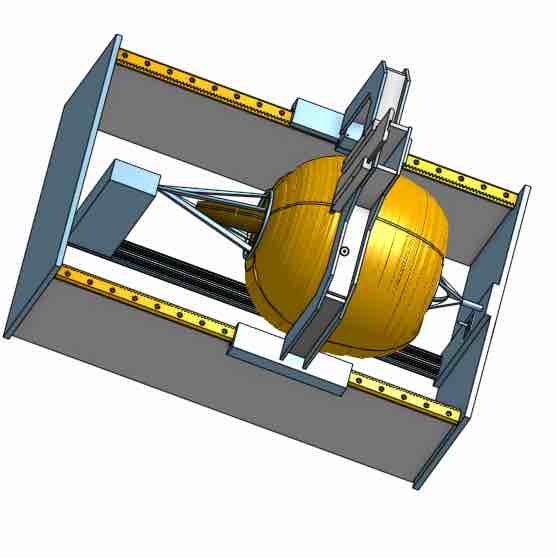
One the the key things that I wanted to simulate was the irregularity of the pumpkin shape. To do this the vector from the DXF was broken into sections and then revolved around portions of the sphere. This resulted in a pumpkin that was not spherical and has an offset center. This will serve as my model for the CAD.
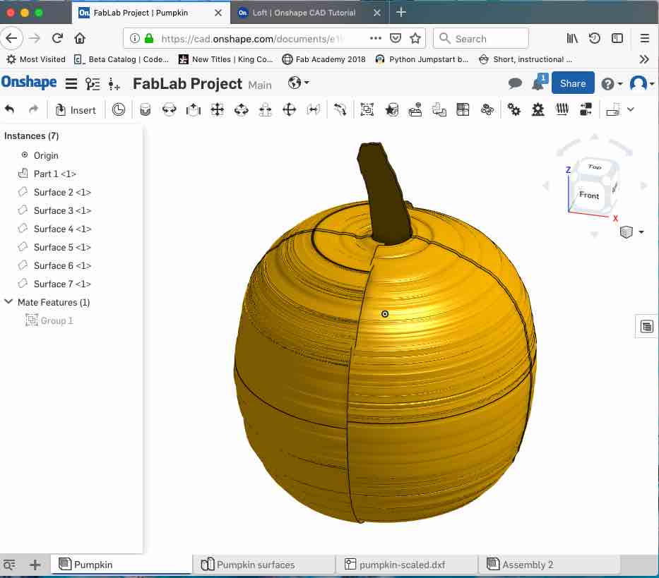
Here are a few pictures of the first version of the final project CAD assembly view. Note the unique feedstock and chuck design to handle the stem and non uniform shape. The router will be mounted on the Z Axis and is not shown in this view. This design is based on the rack and pinion design from the Fab Academy references. This is currently using NEMA 17 steppers. Considering moving to NEMA 23 steppers
Reference Files
Related Projects