Assignment 3: Computer-Controlled Cutting
Project Description
Investigate Laser and Vinyl Cutting
Assignment Details
- Group Assignment:
- Characterize your lasercutter
- Make test part(s) that vary cutting settings and dimensions
- Individual assignment:
- Cut something on the vinylcutter
- Design, lasercut, and document a parametric press-fit construction kit, accounting for the lasercutter kerf, which can be assembled in multiple ways
Cut something on the vinyl cutter
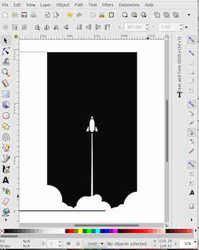
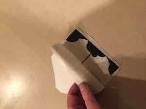
I have a tendency to leave my coffee cup at places that I visit. The objective this assignment was to add something unique to my coffee cup that could be used when describing the cup to get it back. The graphic is from this year's FIRST Robotics competition. Adobe Illustrator with a Flexi-Sign Cutting Master 4 plugin was used to get the design to the Vinyl Cutter.
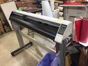
The first step was to cut the vinyl on the vinyl cutter. The Cutter is a Graphtec CE-5000
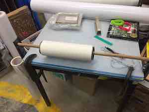
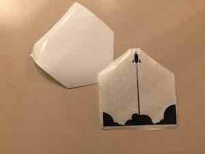
Next step was to weed and apply to the transfer film.
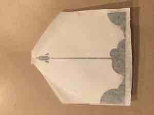
Next step was to pull the backing paper.
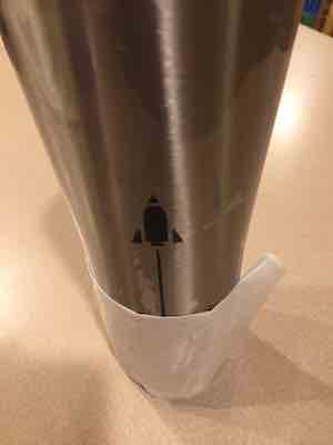
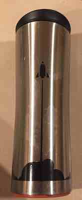
Next step was to apply to the coffee cup and remove the transfer paper.
Characterize your lasercutter. Make test part(s) that vary cutting settings and dimensions
I have access to 4 different laser cutters:
- A newer Eplog at a makerspace in a library
- An older Eplog at the high school where I mentor
- A full Spectrum at my maker space
- A 3W Diode laser that I built
I use a generic laser engrave/cut pattern to get a general idea about the machine specific parameters for power, speed and number of passes
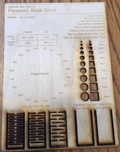
To be able to move designs between these lasercutters, beyond knowing how to modify the feeds and speeds, the curf, material properties and cut characteristics need change based on the specific machine. I have used both the parametric comb approach and parametric versions of key design characteristics. Comb approaches work well for press fit slots or places where the material properties such as thickness influence the design, such as slots. For press fitting two different materials such as cutting a hole for a rod in a sheet, I have found that parametrically cutting prototype holes around the needed size gives the best results. For this week's assignment I created a test cut part that includes several of the key construction elements to validate the correct size for each kind of laser. I'll cover how this was done as part of the design flow.
Design and make a parametric press-fit construction kit
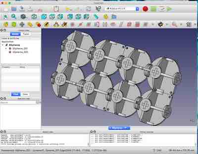
The requirement for this assignment was to build something that could be constructed in different ways. I wanted to go for extra credit and create something that could dynamically change shape and be constructed in different ways. My project was to design and create a press-fit construction kit to similar to the Ugears Flexi-Cubus model. The goal was not to duplicate the design, but to come up with something that behaves like the video. The objective of the design was to be parametric based on a few variables. These variables could be changed for different materials and to change how the pieces fit together. The variables are interrelated, so one change automatically ripples through the design.
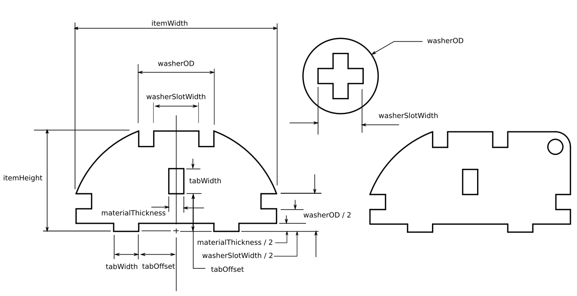
The figure above shows how the variables interrelate for several of the parts. Each of the parts attach with each other. the two lower parts sit next to each other to form one side of a sphere and the slots allow another instance of the part to fit on the other 2 axes. A combination of 6 faces form the sphere. The tabWidth at the bottom of the part, matches the vertical tabWidth above. Thus if the tab width is changed the corresponding slot is also changed. Because two faces of the sphere share the same slot on opposite sides, the height of the tab is 1/2 of the material thickness. Because the face sits in the slot, the width of the slot equals the material thickness plus an adjustment for curf. The tabOffset determines both the spacing between the tabs and the distance from the bottom of the part to the start of the slot. The faces of the cube are joined with a "+" washer. The washerOD matches the the outer size of the slot on the top of the part and 1/2 the distance on the side. The cuts on the side of the part form the other side of the "+" when the faces are joined.
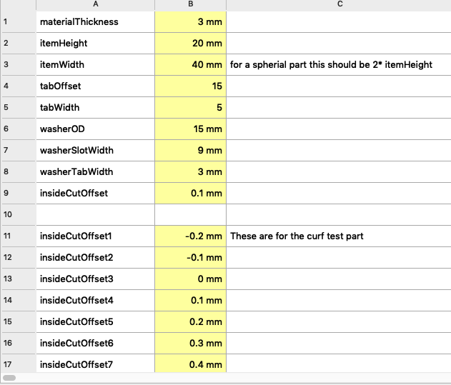
The figure above shows the spreadsheet with the variables for the design. These variables are referenced in the dimensions in each part sketch. When the spreadsheet value changes, the corresponding dimension using the variable updates with the new dimension value. The combination of the washer and slot press fit assembly and the parametric dimensioning serve as the basis for a complete construction set. Changing the width dimension to be something other that half the height can generate parts that are oval and still use the same press fit slots and washer assembly. Changing the dimensions results in a large number of potential parts in the construction set.
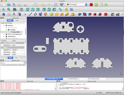
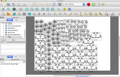
The figure above shows the parts for the design. Each part's dimensions are based on the parameters in the previous spreadsheet.
The figure above shows the calibration block for the slot and washer press fit assembly. The inside cut offset was varied for dimensions that varied based on the laser curf, such as slots based on material thickness. The part showed these options for both the slots and the where the washer pushes on to the end or the part.
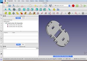
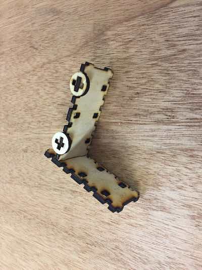
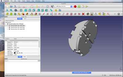
The figure above shows how 2 semi-circle parts back to back form a face of the sphere.
This figure shows the original plan to stack two halves on top of each other, but this caused complications when joining all three dimensions of pieces, so the slot width was reduced from 2*materialThickness to just materialThickness and centering the slot
This figure shows the original plan to set tab height to the material thickness. When I put the pieces together in an assembly it became apparent that the first two pieces filled the slot and there was no room for the pieces on the other side. The resolution was to reduce the tab height to materialThickness / 2
This figure shows the revised design where the tab height was set to 1/2 the material thickness.
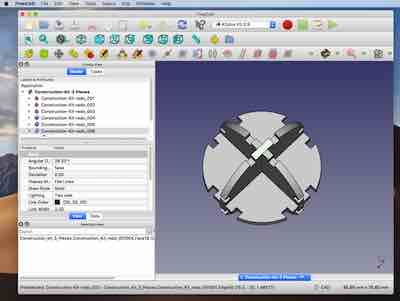
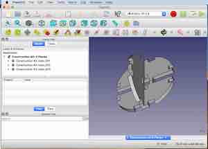
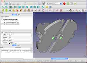
This figure shows how the 3 axes combine based on inserting into slots and leaves a gap and cross for the press-fit washer.
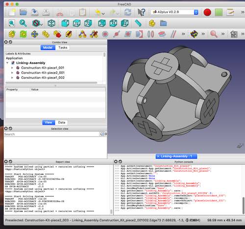
This figure shows how washers press-fit on each side to form a sphere.
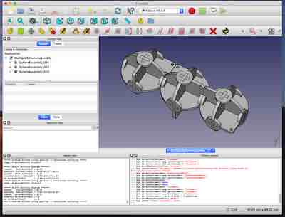
This figure shows how the rotation axis alternates between each attached sphere.
This figure shows how the complete assembly.
The next step was to export the part design as an .SVG file. The only way that I found to do this was through the back door of creating a drawing from a blank template. There may be better ways to do this.
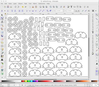
FreeCAD added some extra lines to the SVG that was created. I needed to go into Inkscape and delete these lines before sending the design to the laser cutter.
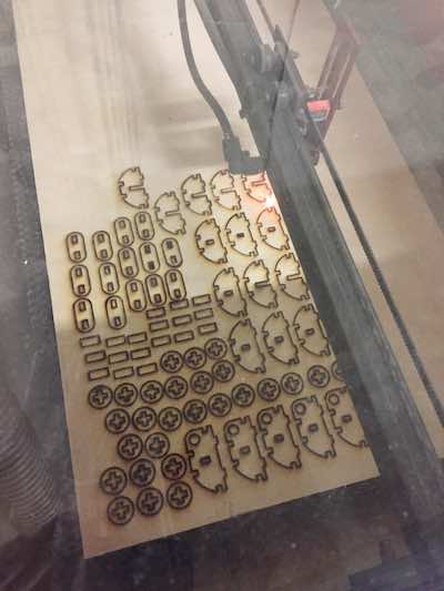
The figure above shows the laser cutter cutting the parts.
I used a Full Spectrum laser with the following settings:
- Speed: 35%
- Power: 90%
- 3 Passes
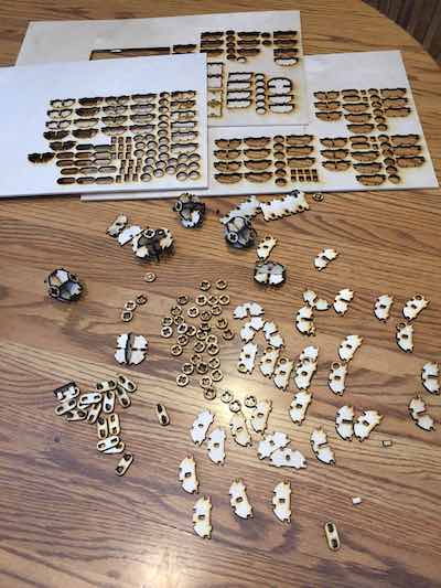
The figure above shows the parts to be assembled.
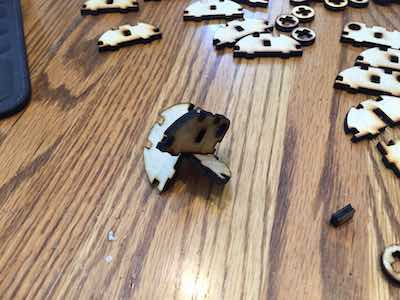
The figure above shows a partial assembly of a sphere.
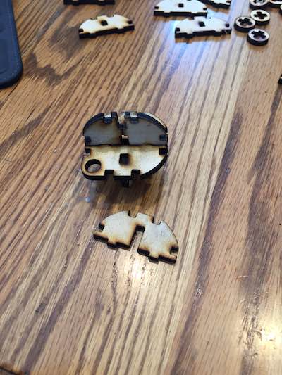
The figure above shows the next step in the assembly of a sphere.
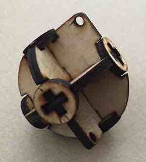
The figure above shows completed sphere.
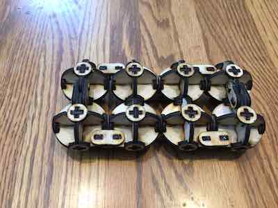
The figure above shows completed assembly of 8 spheres.
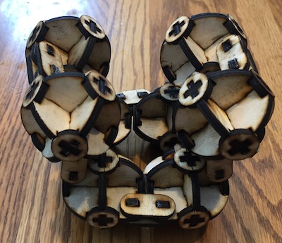
The figure above shows a partially rotated set of spheres.
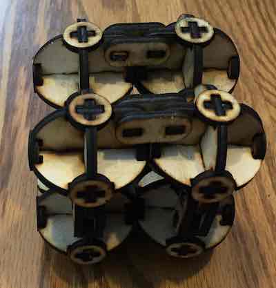
The figure above shows the spheres rotated into a cube.
Key Observations
- Determining which remaining degree of freedom has not be constrained can be very hard. You can try to drag all the points and geometry, but sometimes nothing moves and there are still remaining degrees of freedom. I ended up just starting over and then being vary careful to make sure that the lines turned green after each new operation.
- In retrospect is seems obvious, but it took me a lot time to figure out that the center of the radius of the outer curve needs to be at the midpoint and bottom of the half side. I drew the arc and just let the center point float and it caused all kind of problems. The end result was that when the two halves were put back to back the resulting shape was not symmetric. For a while I replaced the arcs with lines.
- After combining all 6 halves into the simulated sphere, the pieces combined to form a non uniform pattern. The top tab was sized at just the materialThickness, so it resulted in a “-“ rather than a “+” intersection. The top tab was expended to match the horizontal tabs which results in a “+” intersection.
- It took some tuning to factor in the surf and determine the correct depth of cuts that are based on the material thickness
FreeCAD has some "interesting" features
- If you are editing a sketch, the quit button is disabled.
- If you close a sketch that is being edited, there is no way to quit the app other than a system halt
- This is the only app that I have hard crash MacOS. This was the first time I saw the Mac Death screen. Must kill something very low level.
- If you are editing a sketch, the window button to restore from full screen is disabled
- Spreadsheet value changes are lost if you click in another cell or click on the "Done" button (have to press enter to commit a value change).
- Using the equal constrain frequently results in redundant constraint errors - to get around this, used the same spreadsheet attribute in multiple dimensions in the part design
Reference Files
Link to the FreeCAD source file for this assignmentLink to the svg file for the Vinyl Cutting assignment
Related Projects