Document
Output Devices
Output Devices
.png)
For this week assignment I tryed to control the 5V servo motor Sg 90. For control was use the Attiny 45 microchip, and for design the board the Kicad software.
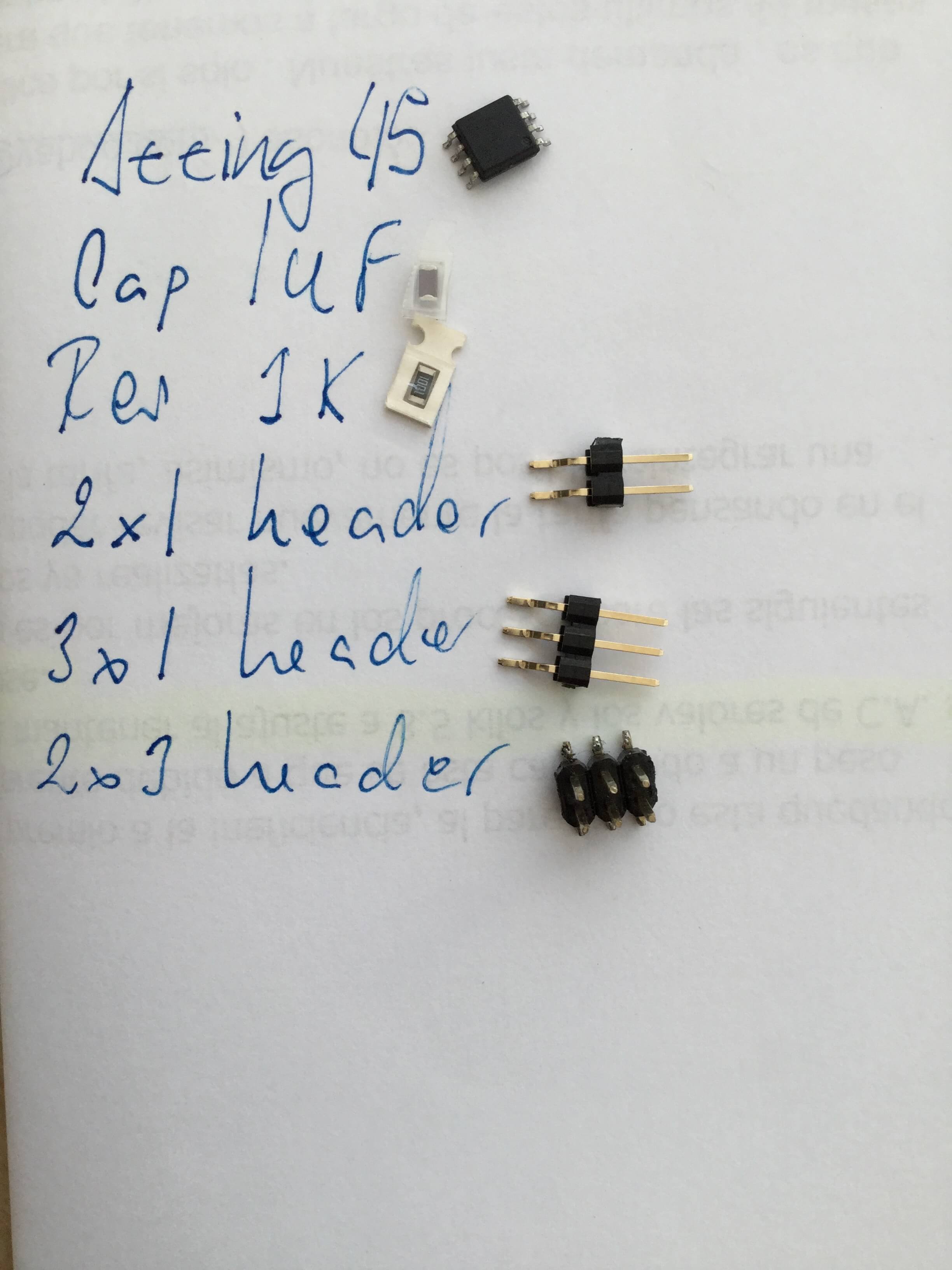
Components:
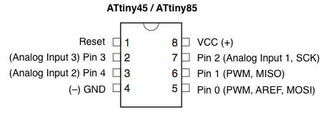
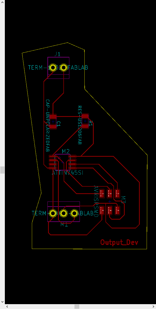
For design the schematic is important to know the pinout of the micrichip: So, in this example I connect the PWM output (for control the servo, the others outputs are ground and current) of the servo with the pin 3 (physically the pin 2) of the Attiny 45.
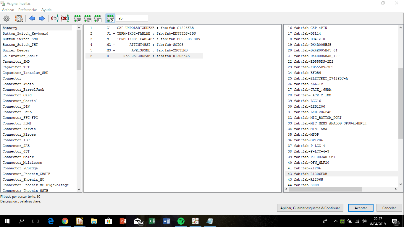
In Kicad is necesary to assign the footprints to the components in the schematic construction.
 Click to expand
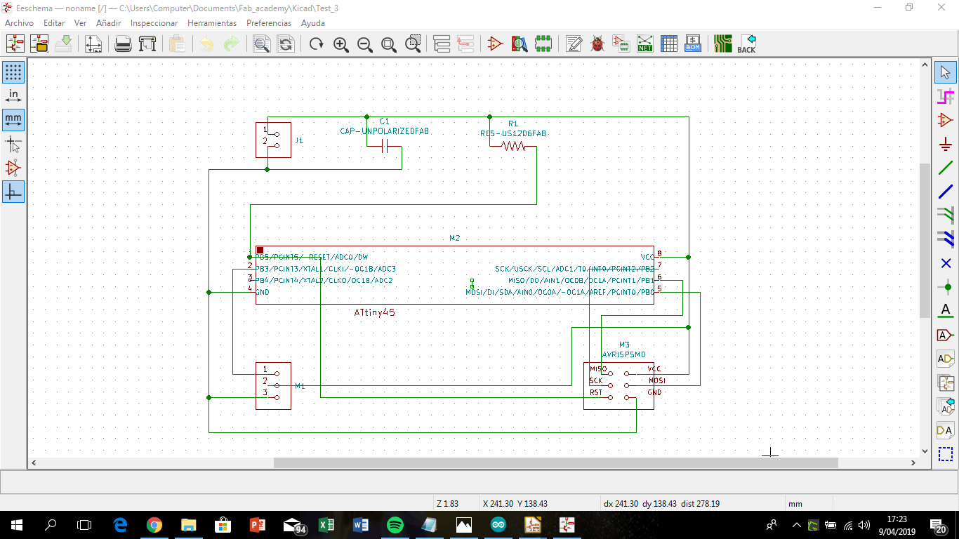
The schematic
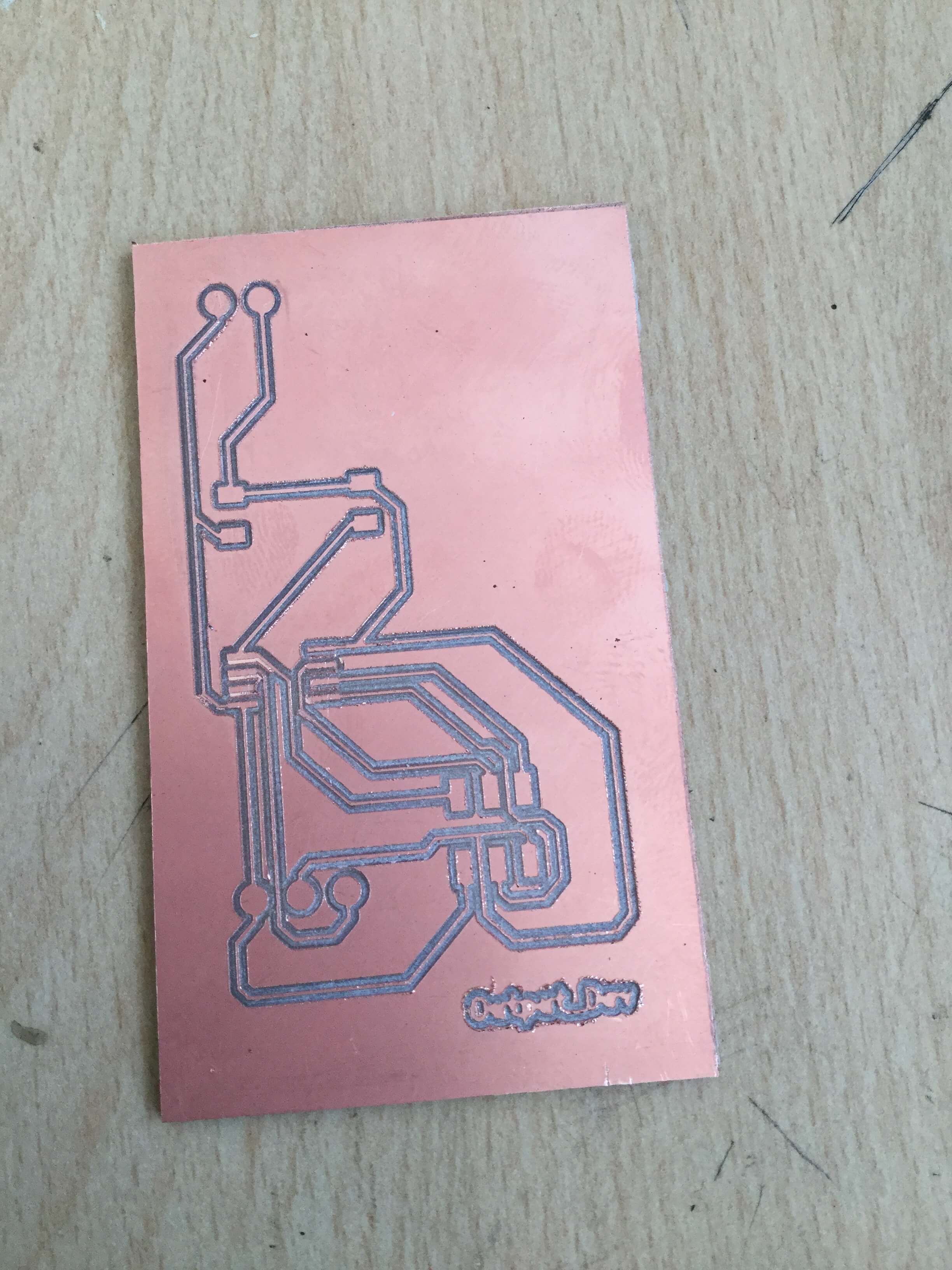
The board: In Kicad (board framework) for print it, I select the layers for traces and interior and export (red and yellow) as PNG, then process in Mods and generate a .rml file.
Once I have the .rml files, I work with Roland Monofab SRM 20 for machining the board.
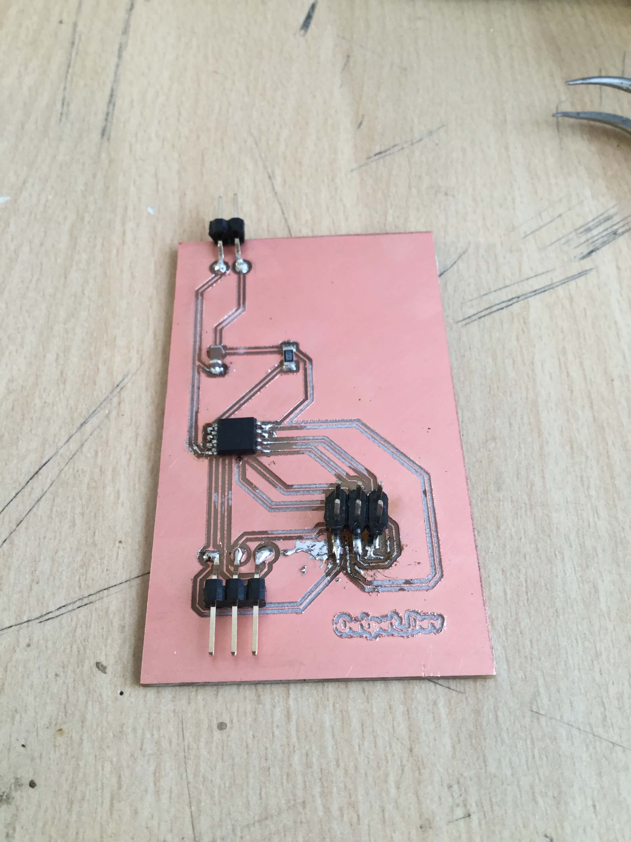
Finally I soldered de components.
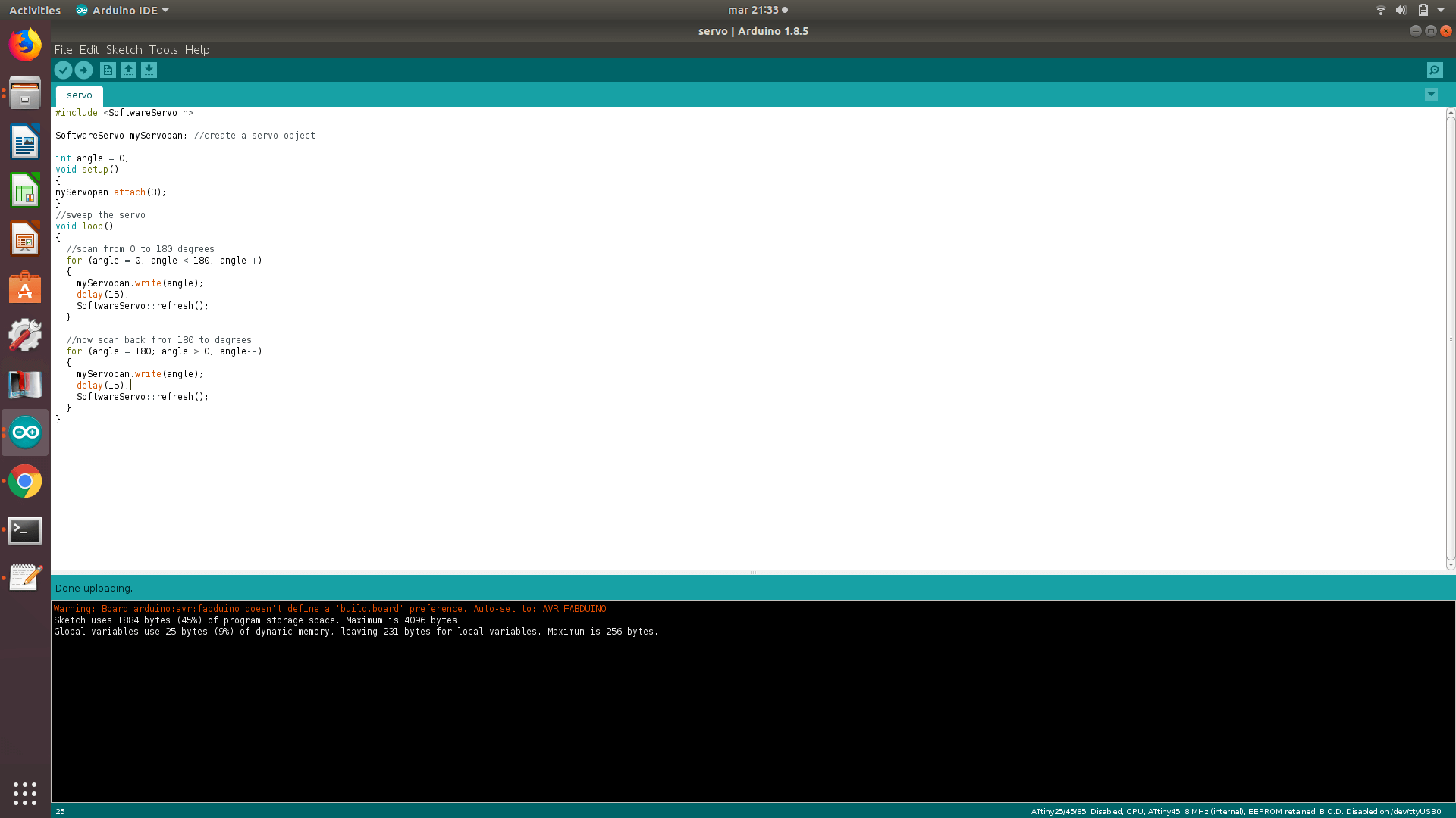
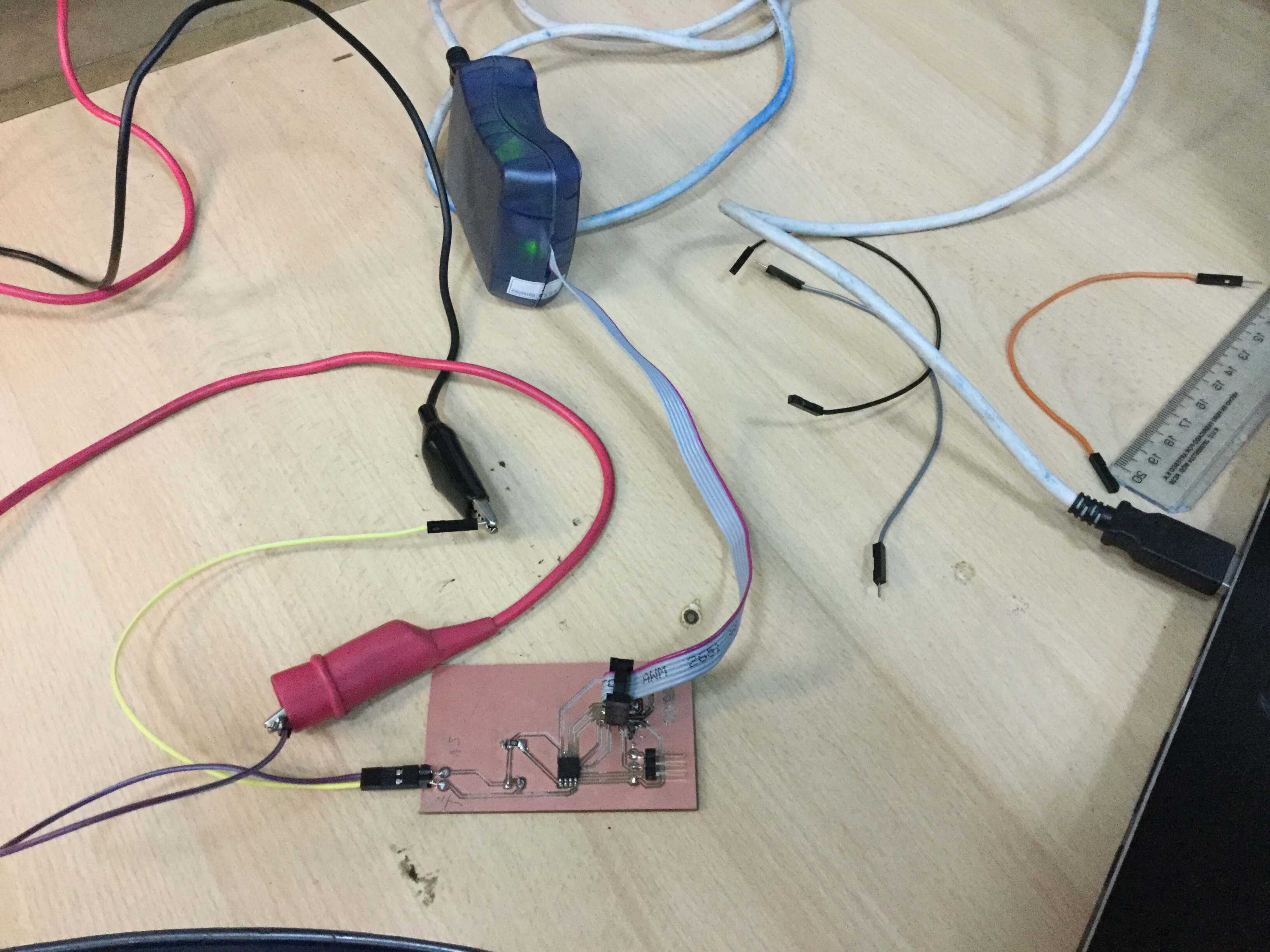
Then, I used the Arduino IDE for load the program in the microchip. For this process I use the AVR ISP as programmer, so I set it in the Arduino IDE.
 Click to expand
 Click to expand
For control the servo, I use the SoftwareServo librarie, and this code, that explains each function of the command line (as comments):
#include < SoftwareServo.h >

SoftwareServo myservo;                 // create servo object to control a servo
                                       // a maximum of eight servo objects can be created

int pos = 0;                           // variable to store the servo position

void setup()
{
  myservo.attach(3);                  // attaches the servo on PB3 to the servo object
  //myservo.attach(4);                  // attaches the servo on PB4 to the servo object (i didn´t use this pin)
}

void loop()
{
  for(pos = 0; pos < 180; pos += 1)  // goes from 0 degrees to 180 degrees
  {                                  // in steps of 1 degree
    myservo.write(pos);              // tell servo to go to position in variable 'pos'
    SoftwareServo::refresh();        // must call at least once every 50ms or so to keep your servos updating
    delay(15);                       // waits 15ms for the servo to reach the position
  }
  for(pos = 180; pos>=1; pos-=1)     // goes from 180 degrees to 0 degrees
  {
    myservo.write(pos);              // tell servo to go to position in variable 'pos'
    SoftwareServo::refresh();
    delay(15);                       // waits 15ms for the servo to reach the position
  }
}
Finally, I test the board, using a 5V current source and the servo moved.

Asignment goals
- Measure the power consumption of an output device (Group assignment).
- Add an output device to a microcontroller board you've designed and program it to do something.
Board Files
Learning outcomes
- Demonstrate workflows used in circuit board design and fabrication.
- Implement and interpret programming protocols.
Have you?
- Described your design and fabrication process using words/images/screenshots, or linked to previous examples.
- Explained the programming process/es you used and how the microcontroller datasheet helped you.
- Outlined problems and how you fixed them
- Included original design files and code