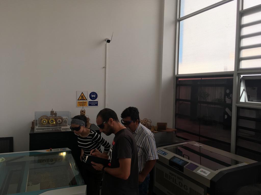
Trotec Speedy 400 (see specs of the lasercutter)
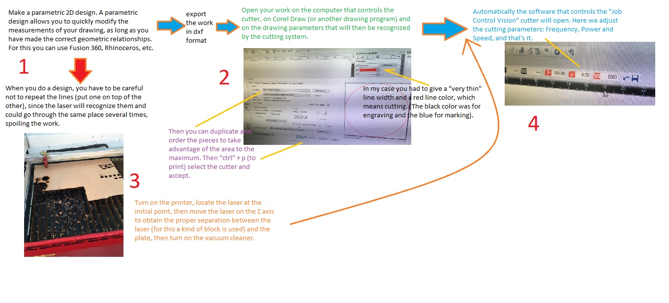
Workflow to make a laser cut
To do a good job of laser cutting it is necessary to know what parameters are useful so that the pieces are well fitted, not too loose or too hard, in that sense it is important to consider the kerf or loss of material due to the machining performed by the laser, since this modifies the final size of the cut, and the only way to obtain reliable values is by testing. Small circles were design on Rhinoceros, exported to .dxf file extension and opened on CorelDraw (the machine is configured to be used with this software) and cutted with different parameters of power and speed.
 It is important to note that if you are going to design the pieces that fit, you need to know how much you have to add (or remove) the dimensions that will fit due to the effect of the loss of material by the laser cut, although they are very small dimensions, are determinants.
Determination of cutting parameters and kerf
-
Cutting parameters
Kerf
Interference fit on C
Interference fit on U
Several circles of a 3 mm MDF sheet were cut using different parameters (power, velocity and frequency). Based on the experience of using the machine, the value of the frequency was left constant (5000), and the power remained between 100 and 95, so the speed was mainly changed, starting from 0.9 and varying 0.05 until reaching a speed of 0.2. It was observed that at speeds between 0.9 to 0.65, the laser only engrave, from 0.6 the laser made a clean cut and from 0.55 to 0.2 the short laser burned a bit the edges of the material. In conclusion, the parameters suitable for the cut were, speed of 0.6, power of 100 and frequency of 5000.

To calculate the kerf of machine, we need to measure the outer borders and the inner borders of the cut, then divide this rest by 2.
Kerf = (50.1 – 49.9)/2
kerf = 0.1 mm
In the Interference fit on C only the piece that has the concave socket loses material, the part that enters remains constant and is the thickness of the material, which does not suffer any cut. In this way it is sought to remove some millimeters to the width so that a good adjustment is achieved, that is, neither very strong nor very weak.
A kind of "comb" was designed, where a different width was given between one point and the next, starting with a width of 3.1 mm and decreasing 0.01 mm until reaching 3.00 mm.
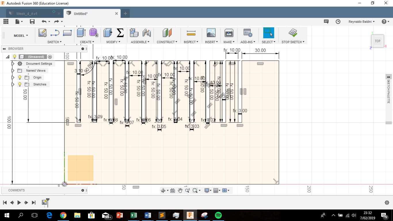
The structure of the parametric design would allow to make changes of the distance changing only the initial width and the value of the difference, in case the fit is very soft with the initial values.
With the first comb, which started with a width of 3.1, then 3.09 and so on until 3.0, the lace was very ground so the task was repeated, but now starting with a 3 mm gap and increasing a progressive difference of 0.01 until reaching 2.9 mm. It was found there was a good adjustment at 2.96 mm
It would have been better to make the comb with shorter tips, the long tips could yield under pressure that exerts the adjustment with the other piece.
In the u-type lace, there is a loss of material in the convex part and in the concave part, so you should look for how many mm should be added to the convex part and remove the concave part to get a good fit.
To determine the proper fit in the "c" type socket, it was added to the external part and removed to the internal part from 0.01 mm to 0.05 mm, and it was found that the optimum fit was adding +/- 0.02 mm to the base width.
Cut something in the vinylcutter
First I extracted from the internet an image that I liked, it is the cover of a Peruvian cumbia record. Then I imported the image from the Inkscape program, here I used the command "vectorize bitmap", the image was black and white and it was easy to edit because the nodes could be modified.
Vinil files (ptl/svg)
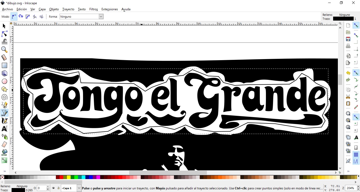
Then I used the "Uniconvertor" program to export the default Inkscape file (.svg) to an ".AI" file, which is the extension read by the cutter driver (Roland Cut Studio).
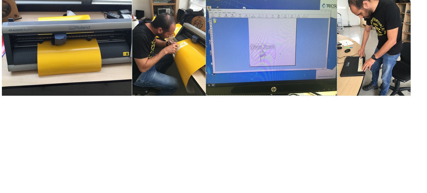
I used the Roland Camm 1 Servo GX 24 cutter (see specs of the vinilcutter). The parameters to be defined were knife strength and height. The first cuts did not go well, the printer did not cut, I started with a force of 90 gf, and in 140 gr it was just cut. At the time of cutting, due to the details of the drawing, the cutter damaged the finish a bit, so I ended up simplifying the drawing and I was left alone with the letters. For this, in Inkscape, I delimited the letters with a line and used the "intersection" command. Then it was possible to make a good ccc cut.
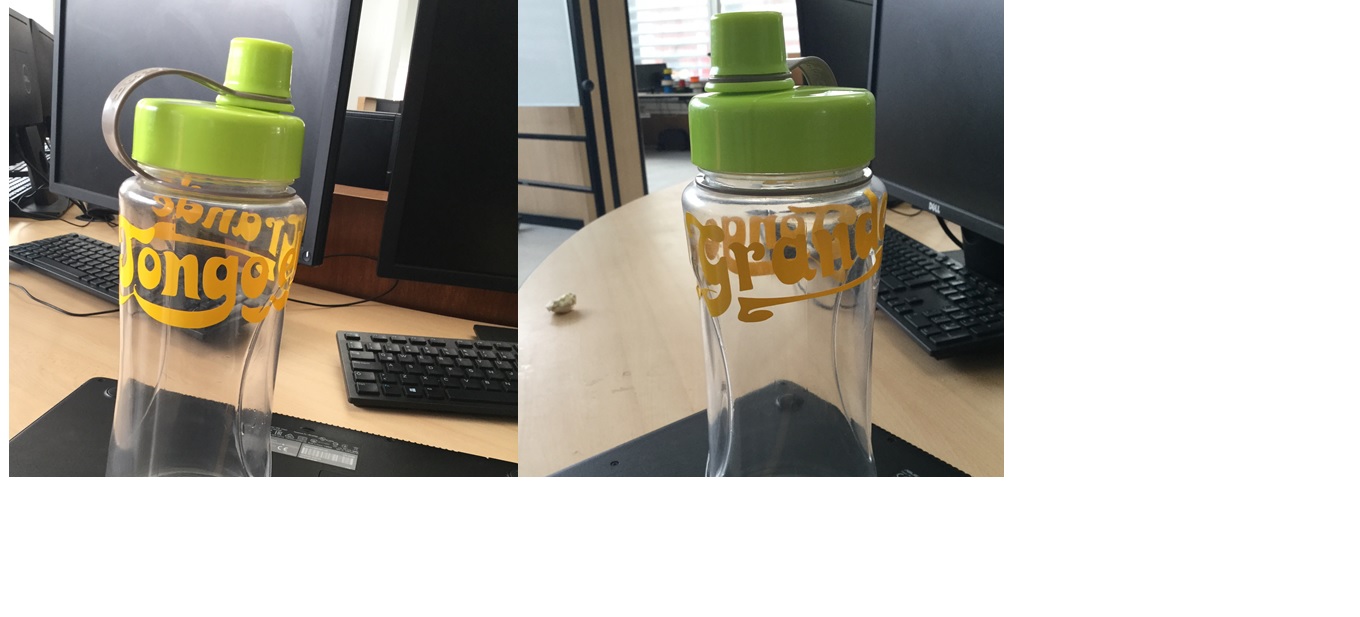
In the picture: the process of vinil cutting,first arrange the vinyl in the cutter respecting the guidelines of the machine, the I carefully removed the cut vinyl part of the supporting paper,I finally tried to paste the sticker on my computer, but it was not possible because it is not a smooth surface.
Design, lasercut, and document a parametric press-fit construction kit, accounting for the lasercutter kerf, wich can be assembled in multiple ways
In my first attempt (and until now the only one) I used Fusion 360 to make my design and I started with a simple piece. In addition, for the type C socket I used 2.95 mm (ie - 0.05 mm considering that the thickness of the MDF sheet is 3mm). Although, according to the tests I did in group work, I had a good fit when I used a width of 2.96 (-0.04 mm) I wanted to make sure that the lace was strong.
So for desing in Fusion 360, I began to sketch the idea in 2d desing, for this I use the change parameters option for create a parameter list, acording to the kerf reference, the use extrude for 3d the sketch.
So, I design a square with c joint, in diferent sizes and circles.
3d Fusion 360 file
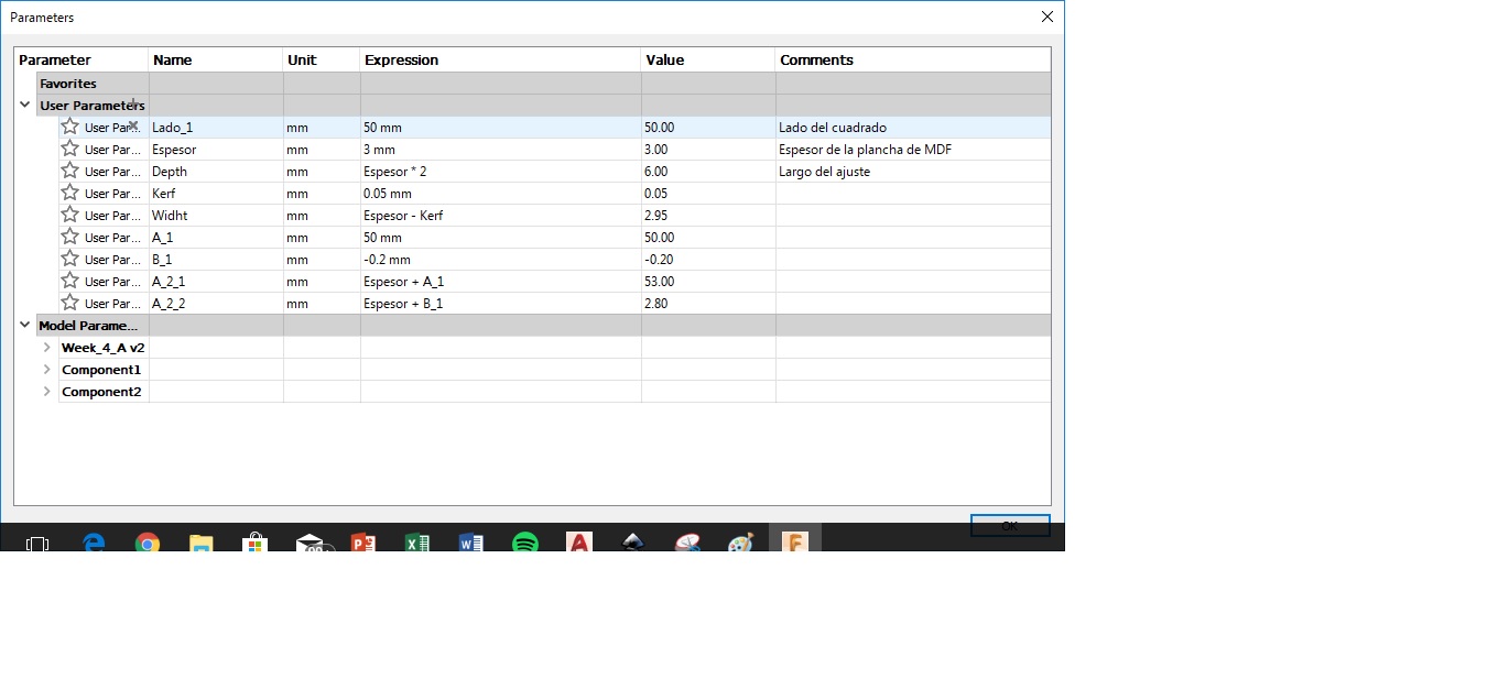
In addition, I wanted to make the model in 3D to see what was left, however, I found the problem that when I managed to duplicate a piece, I could not make the parameter is also copied, so I gave up to continue the parameterization. Another problem I had was that I drew some curved lines, but when exporting to DXF format and opening the drawing in Corel Draw to print the pieces, I did not recognize the curved lines, so I left straight lines only. The final design should look like this.
The picture represents the final asemble model.
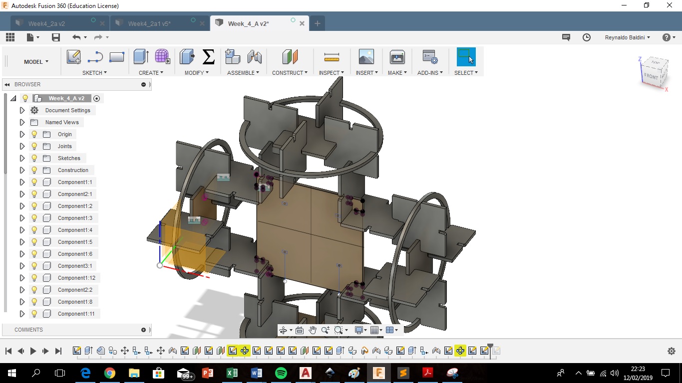
Although 3D design was not useful for laser cutting, just to visualize the final result. I went back to designing the pieces, but now only in 2D with the intention of making a first attempt to cut and assemble. I can not do the smoothing to the edges (chamfer) since I did not find the option to do it in 2D, only in 3D.
Finally I sent the drawing from Fusion 360 to Corel Draw in DXF format using the Autodesk A360 web service.
DXF File
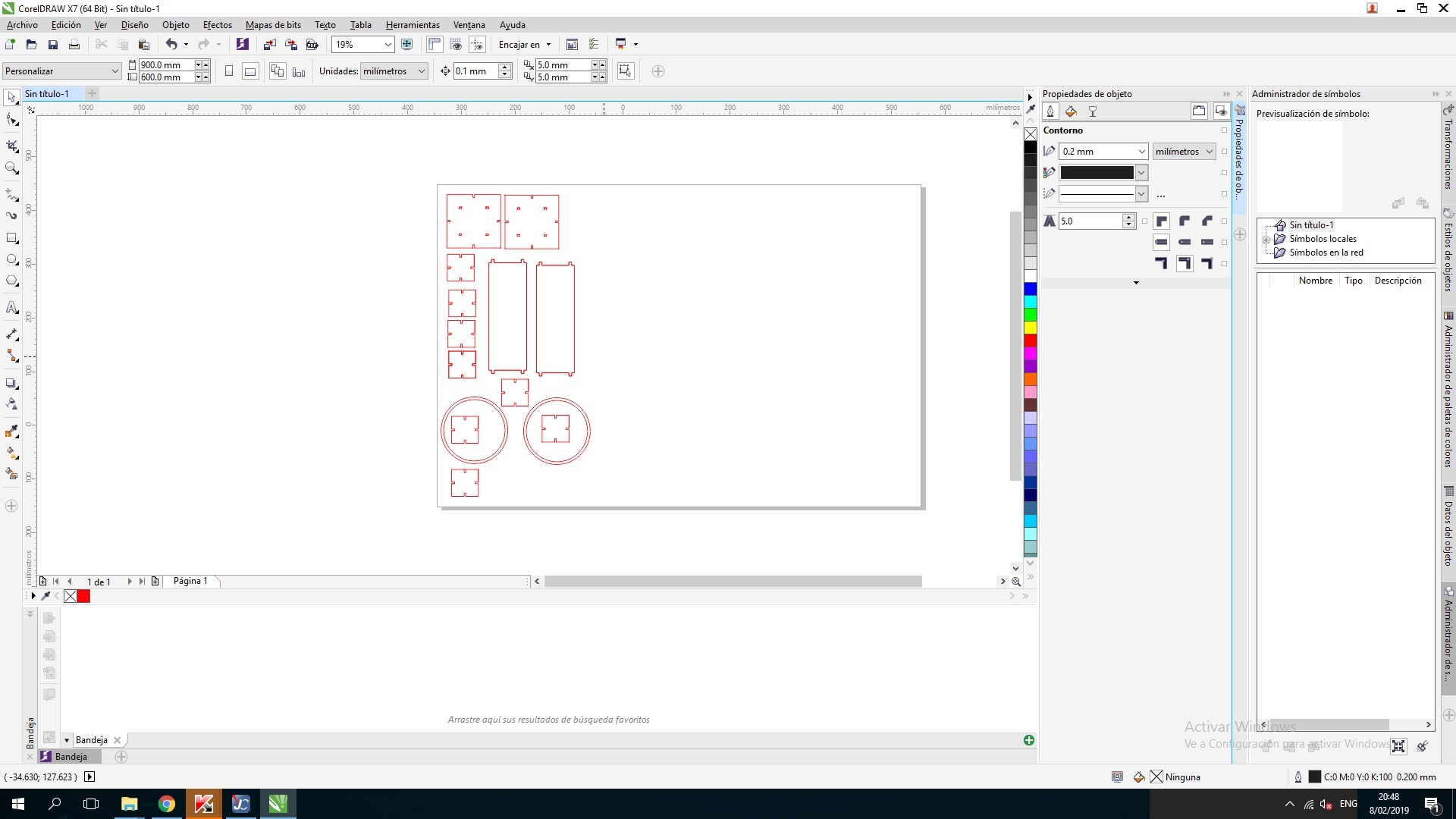
About the laser cutting software
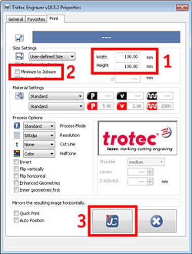
Trotec Job Control is the default software for control the laser cutter. Once you have the design in DXF file open in a program such as Corel Draw, is possible to send the job through print command. After defining the framework of the design in the print options of Corel Draw, select the Job Control option for access to the software. The basic way for send to cut from the Job Control needs only define the basic parameters (power, velocity, and frequency), and usually define a line color for differentiating engrave and cut, then only send to the machine.
Cut
Material: I use the 3 mm MDF again
Cutting parameters
- Power: 95
- Velocity: 0.6
- Frequency: 500
Security recomendations before cutting
- Never take your eyes off the machine, there is a risk of fire
- Use lenses with UV filter or better avoid looking directly at the laser, it damages your eyesight.
- Close the lid and turn on the air extractor, toxic gases and particulate material can be generated.
.jpg)
As I made a first trial cut, I decided not to cut all the pieces so as not to waste material, however, it was the only cut I made. The "C" fitting of 2.95 mm (or -0.05 mm) turned out to be too tight, which makes the pieces difficult to handle. On the other hand, for the "u" type lace I used a kerf of (+/- 0.02) however it also turned out to be very tight and difficult to manipulate, even when I tried to separate the pieces, I ended up breaking them in lace.