7. Electronics design
The topic of this week is “Electronics Design”. I learned how to design the circuit board and practice it. This part is also I want to learn in depth. Class video is here.
Assignment
Group Assignment
- use the test equipment in your lab to observe the operation of a microcontroller circuit board
Individual Assignment
- redraw the echo hello-world board, add (at least) a button and LED (with current-limiting resistor) check the design rules, make it, and test it
- extra credit: simulate its operation
- extra credit: render it
In the group assignment, we checked how to use Multimeters and Oscilloscope for testing our circuit board. Please see our week 7 group assignment page.
Checking a schema of echo hello-world board
The task of individual assignment is “redraw the echo hello-world board”, and add (at least) a button and LED. First, I checked sample of echo-hello world board.

It contains the following components.
| components | num |
|---|---|
| ATTiny 44 | 1 |
| 10K Register | 1 |
| 499 Register | 1 |
| 1uF Condenser | 1 |
| 20MHz Resonator | 1 |
| 6pins FTDI Jamper | 1 |
| 2x3 pin for ISP | 1 |
I decided to add one switch and one LED. To add a switch and a LED, I need one more 10K Register and 499 Register.
Circuit Design by Autodesk Eagle.
I used Autodesk Eagle to redraw echo hello-world board.
Schema Design
First, I started to design schema of the board by using schematic mode of Eagle. With following Tutorial Page, I installed fab.lbr library.
Next, I added each components on the schema. Corresponded symbols of each schema are here:
| ATTiny 44 | 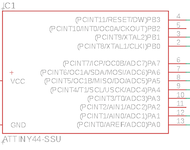 |
Crystal | 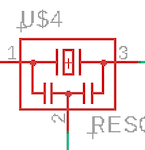 |
| Register | 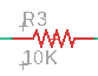 |
6pins FTDI Jamper | 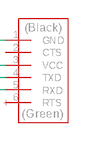 |
| Condenser | 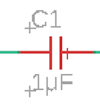 |
2x3 pin for ISP | 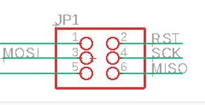 |
Then, I connected each components with referring a schema of echo-hello world board.
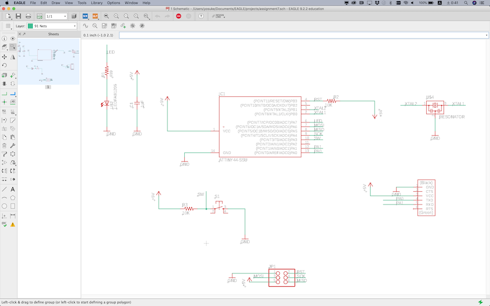
Finally, I try ERC (Electrical Rule Check).
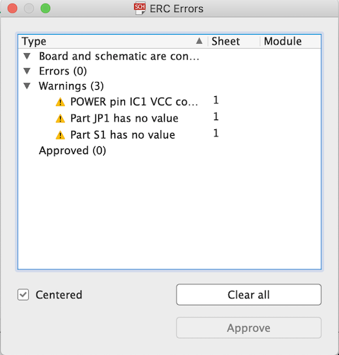
No, error found out, but I had some warning message. I tried to fix those warning, but finally I left some of them. For example, to fix the error “POWER pin IC1 VCC connected to +5V”, I unwired +5V symbol and VCC on IC1. However, a error “No SUPPLY for POWER pin IC1 VCC” was occurred.
Pattern Design
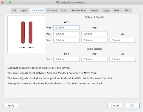
The next step is to design a circuit. I switched design mode of the EAGLE and set up some parameters.
First, I set parameters for clearance. All parameters set in 0.4 mm because it should be the same with the diameter of endmills (1/64 inch) when cutting in SRM-20.
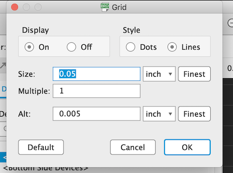
Grid size setting: I set 0.05 inch.
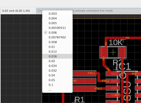
Also, changing line width. It set “0.016” inch.
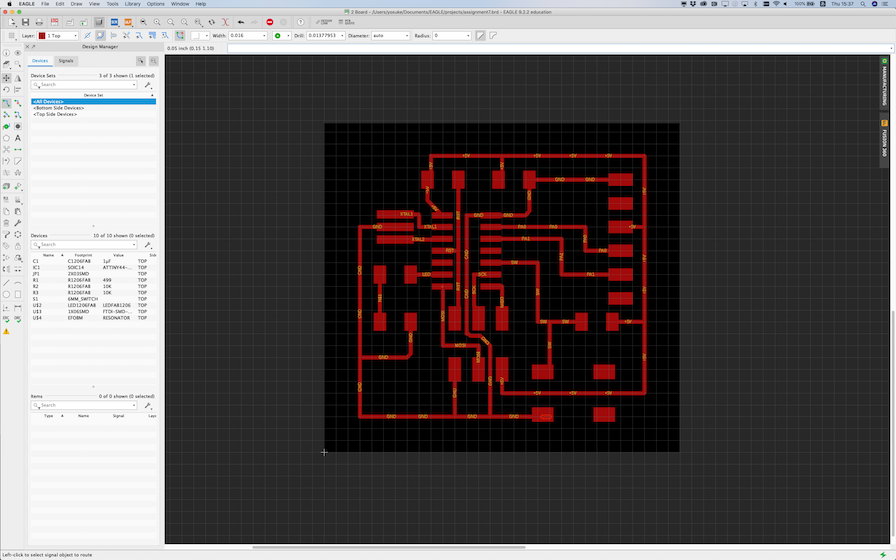
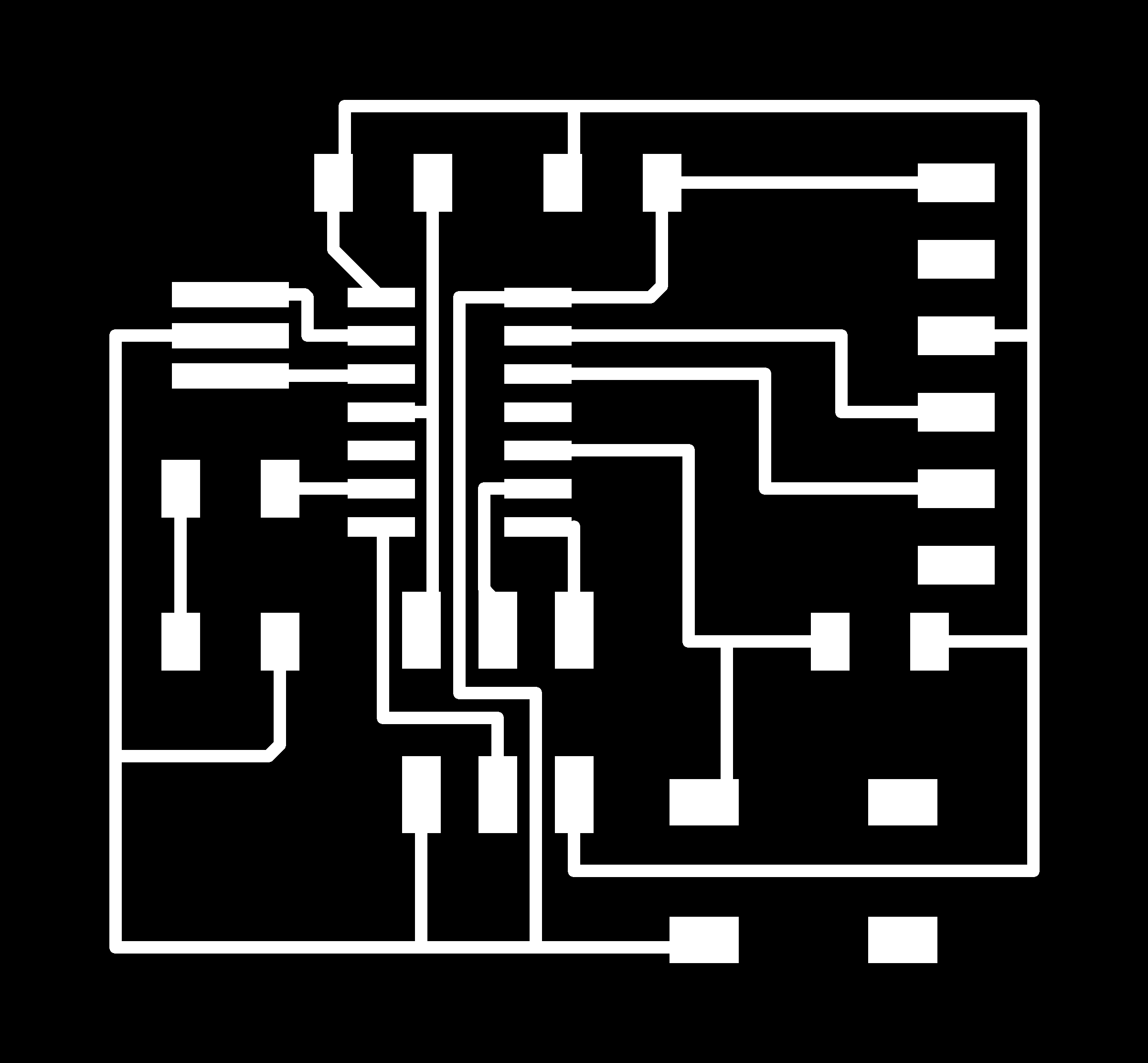
Then, draw the pattern of the circuit.
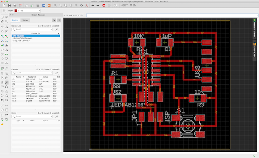
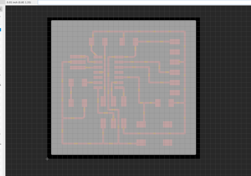
Before exporting to PNG file, it is better to do “Design Rule Check”. It could be on the left side corner icon:

I checked the design rule and it could be found some warning for wire stabs (some pathes that is not needed).
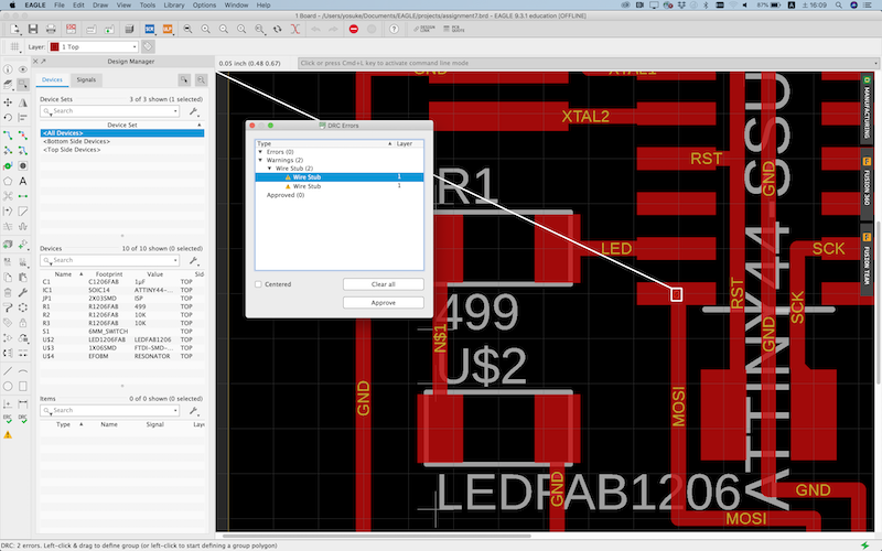
After fixing errors and warnings, I checked the design rule, again. And, I could find out the message that there are no errors.

Export to PNG file
To export PNG file that trace the circuit, first, open the layer setting, then set to visible only “Top” layer.
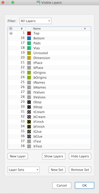
And, I could see only the circuit lines.
Select “File” -> “Export” -> “Image”. Then, setting the parameter as following
- File: Put any name of file.
- Check on to “Monochrome”
- Resolution: 800
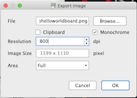
Then, export to PNG file, and I will import it into the mods, later.
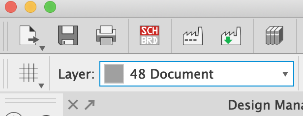
Next, export an outline of the board. First, opening layer setting, again. Then, I set only “top” and “Document” layer visible.
Then, I switched target layer (for editing) from “top” to “Document”.
Using “polygon” to draw the outline.

I draw a rectangle that would enclose the circuit.
Then, opening “layer setting”, agaon. Then, I set to visible only “Document” layer.
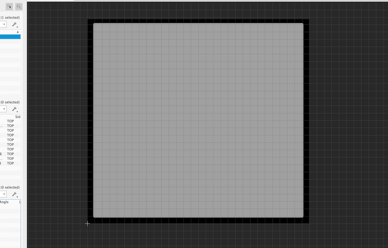
Exporting to PNG file, it would be the same process when exporting trace file of the circuit. And, I could see the following PNG file.

Making CAM file in mods.
To generate the path for milling the board, I used mods. First, I import the programs for milling on Roland SRM-20 with “program” -> “open server program” -> “Roland” -> “mill” -> “SRM-20” -> “PCB png”.
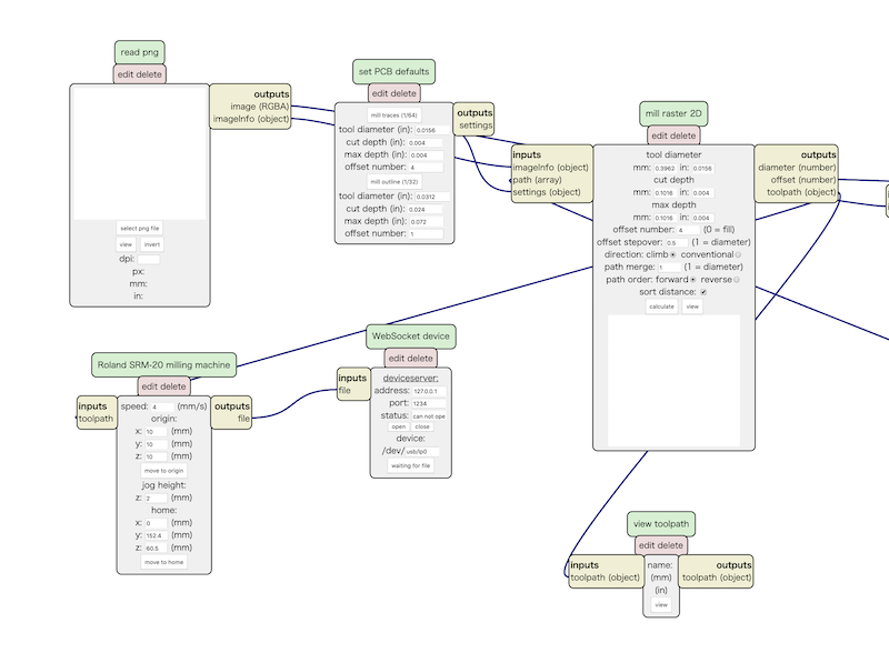
To generate the milling path for tracing circuit, set each parameters of modules as following.
- “read png” module: import the png file
- “set PCB default” module: select “mill trace (1/64)”
- “mill raster 2D” module: confirm tool diameter would be 0.3962 mm (0.0156 inch). This parameter is almost the same with the design rule of the circuit that set in the EAGLE.
- “Roland SRM-20 milling machine” module: This is important section. It determine the parameter when milling on that machine. Here, confirming speed would 4 mm/s, and I should set each XYZ origin parameter to zero.
Also, to export the path into the file (rml), I added the module of “save file” (“module” -> “open server module” -> “file” -> “save”), and connect “inputs” of the “save file” module to “output” of the “Roland SRM-20 milling machine” module.
Then, do “calculate” on the “mill raster 2D” module, and the path file is generated.
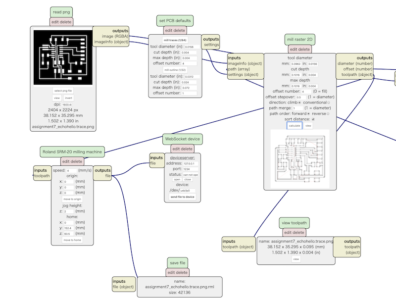
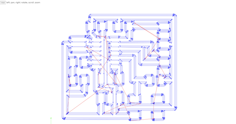
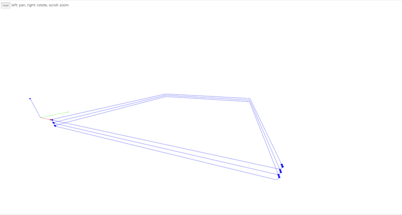
I could see the preview of the path on the “view toolpath” module to confirm whether each path are generated correctly.
To generate the milling path for the outline, I did the same process to setting up each parameters of modules. Only the different parameter from tracing circuit is the tool diameter. To mill the outline, I changed this parameter to “mill outline (1/32)”.
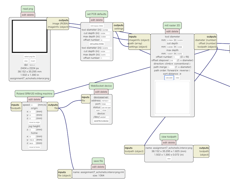
Then, do “calculate” and the path file for the outline is generated. Also, checking the preview.... mods is very nice that would show the path in 3D views.
Milling and Solidering
This section is a review of the lesson about “Electronics Production”. The task for setting up Roland SRM-20 for milling PCBs are:
- Putting the PCB in the SRM-20, it should be steady and flat with taped down.
- set 1/64 endmill for milling circuit (or 1/32 mill for milling outlines)
- Use VPanel and set X/Y/Z origin point, and move the endmill position to the original.
Then, read rml files and start from the milling of the circuit part.
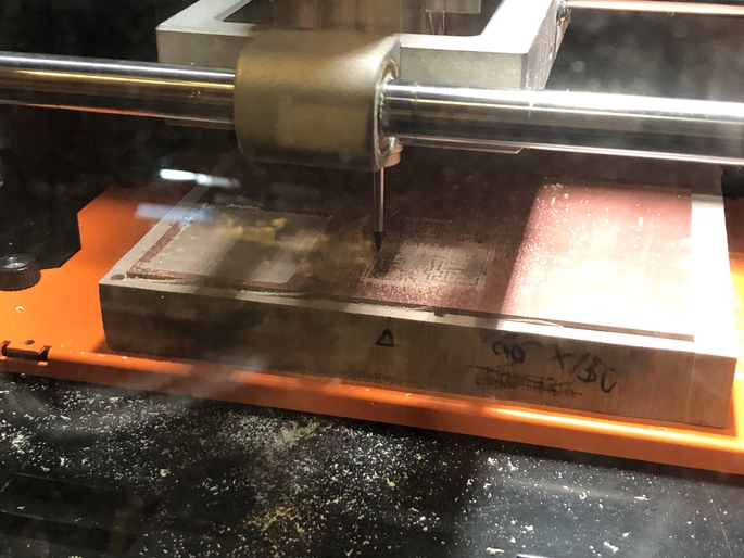
Next, milling of the outline of the board.
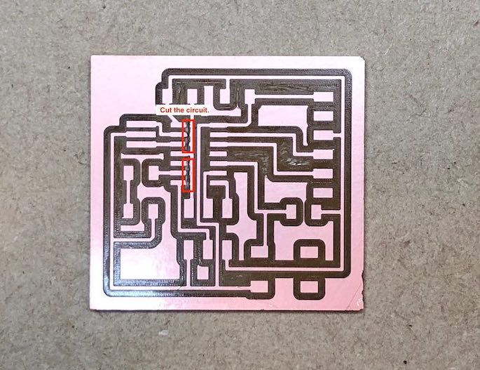
After finished the milling, I found out that some small lines could not be milled.
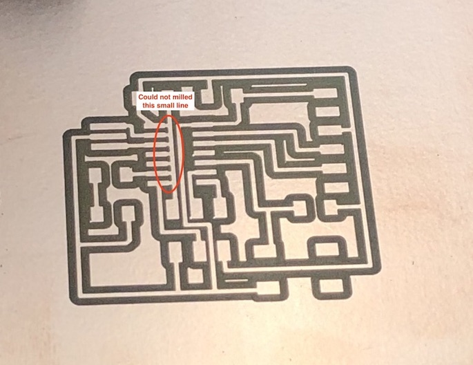
Therefore, I used Ultrasonic cutter for cutting those small lines.
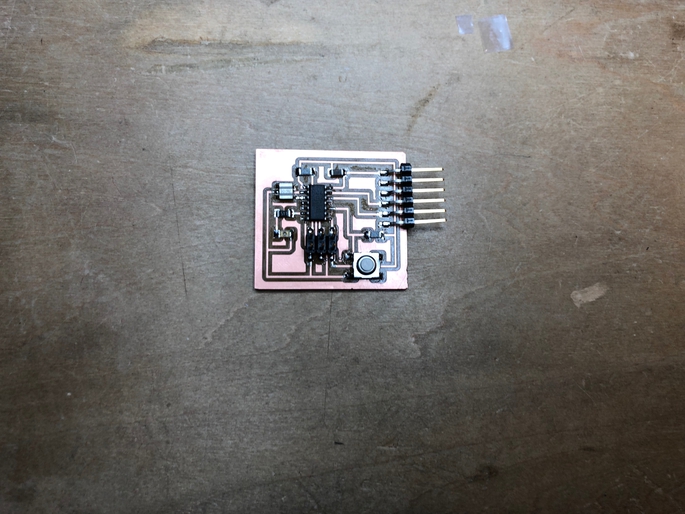
Then, I find the parts in the lab inventories and solidered them.
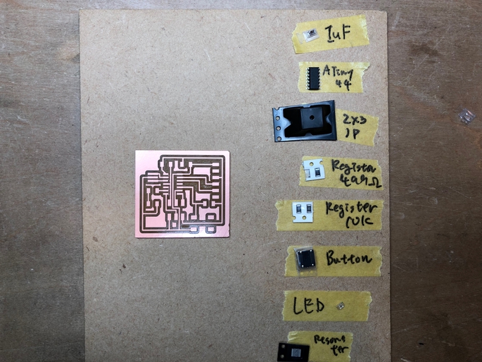
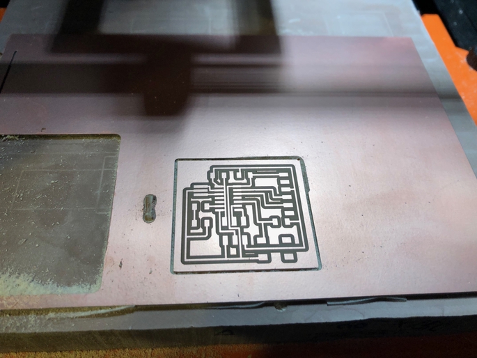
.... The echo hello world is completed. It is the first PCB that I designed the circuit and milled it by myself.
Connecting to FabISP and writing test
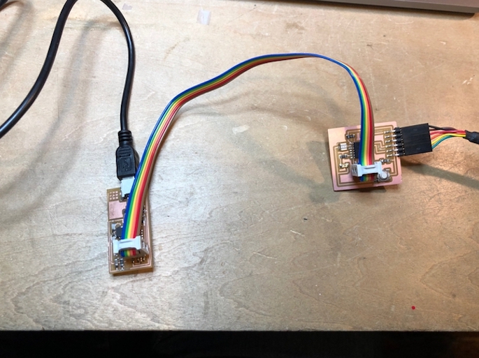
In order to check the board works, I tried to program a sample code of echo hello-world board. First, I connected my designed board to FabISP which I made in the assignment of Electronics Production.
Then, download sample C program and Makefile.
First, I compiled C program and generate hex file for the board.
$ make -f hello.ftdi.44.echo.c.make
avr-objcopy -O ihex hello.ftdi.44.echo.out hello.ftdi.44.echo.c.hex;\
    avr-size --mcu=attiny44 --format=avr hello.ftdi.44.echo.out
AVR Memory Usage
----------------
Device: attiny44

Program:     758 bytes (18.5% Full)
(.text + .data + .bootloader)

Data:         64 bytes (25.0% Full)
(.data + .bss + .noinit)
Then, I tried to write fuses into the microcontroller.
$ sudo make -f hello.ftdi.44.echo.c.make program-usbtiny-fuses
Password:
avr-objcopy -O ihex hello.ftdi.44.echo.out hello.ftdi.44.echo.c.hex;\
    avr-size --mcu=attiny44 --format=avr hello.ftdi.44.echo.out
AVR Memory Usage
----------------
Device: attiny44

Program:     758 bytes (18.5% Full)
(.text + .data + .bootloader)

Data:         64 bytes (25.0% Full)
(.data + .bss + .noinit)


avrdude -p t44 -P usb -c usbtiny -U lfuse:w:0x5E:m
avrdude: Error: Could not find USBtiny device (0x1781/0xc9f)

avrdude done.  Thank you.

make: *** [program-usbtiny-fuses] Error 1
.... I could not write them.
Problem
The problem is the cable that connect the FabISP and the designed board. The cable is twisted and it makes mismatche of positions of ISP pins.
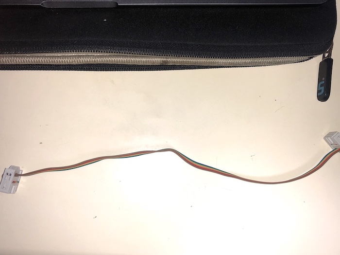
Therefore, I made the cable for ISP, again, not twisting the cable.
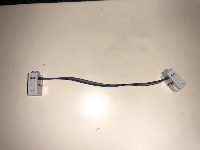
2nd Try for programming.
With using fixed cable, I connected FabISP and my designed board, again.
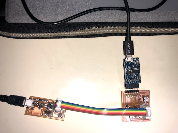
Then, I tried to write fuses into the microcontroller.
$ sudo make -f hello.ftdi.44.echo.c.make program-usbtiny-fuses
avr-objcopy -O ihex hello.ftdi.44.echo.out hello.ftdi.44.echo.c.hex;\
avr-size --mcu=attiny44 --format=avr hello.ftdi.44.echo.out
AVR Memory Usage
----------------
Device: attiny44

Program:     758 bytes (18.5% Full)
(.text + .data + .bootloader)

Data:         64 bytes (25.0% Full)
(.data + .bss + .noinit)


avrdude -p t44 -P usb -c usbtiny -U lfuse:w:0x5E:m

avrdude: AVR device initialized and ready to accept instructions

Reading | ################################################## | 100% 0.00s

avrdude: Device signature = 0x1e9207 (probably t44)
avrdude: reading input file "0x5E"
avrdude: writing lfuse (1 bytes):

Writing | ################################################## | 100% 0.00s

avrdude: 1 bytes of lfuse written
avrdude: verifying lfuse memory against 0x5E:
avrdude: load data lfuse data from input file 0x5E:
avrdude: input file 0x5E contains 1 bytes
avrdude: reading on-chip lfuse data:

Reading | ################################################## | 100% 0.00s

avrdude: verifying ...
avrdude: 1 bytes of lfuse verified

avrdude: safemode: Fuses OK (E:FF, H:DF, L:5E)

avrdude done.  Thank you.
It is succeeded. Next, I write the program into the microcontroller.
$ sudo make -f hello.ftdi.44.echo.c.make program-usbtiny
avr-objcopy -O ihex hello.ftdi.44.echo.out hello.ftdi.44.echo.c.hex;\
avr-size --mcu=attiny44 --format=avr hello.ftdi.44.echo.out
AVR Memory Usage
----------------
Device: attiny44

Program:     758 bytes (18.5% Full)
(.text + .data + .bootloader)

Data:         64 bytes (25.0% Full)
(.data + .bss + .noinit)


avrdude -p t44 -P usb -c usbtiny -U flash:w:hello.ftdi.44.echo.c.hex

avrdude: AVR device initialized and ready to accept instructions

Reading | ################################################## | 100% 0.00s

avrdude: Device signature = 0x1e9207 (probably t44)
avrdude: NOTE: "flash" memory has been specified, an erase cycle will be performed
         To disable this feature, specify the -D option.
avrdude: erasing chip
avrdude: reading input file "hello.ftdi.44.echo.c.hex"
avrdude: input file hello.ftdi.44.echo.c.hex auto detected as Intel Hex
avrdude: writing flash (758 bytes):

Writing | ################################################## | 100% 0.58s

avrdude: 758 bytes of flash written
avrdude: verifying flash memory against hello.ftdi.44.echo.c.hex:
avrdude: load data flash data from input file hello.ftdi.44.echo.c.hex:
avrdude: input file hello.ftdi.44.echo.c.hex auto detected as Intel Hex
avrdude: input file hello.ftdi.44.echo.c.hex contains 758 bytes
avrdude: reading on-chip flash data:

Reading | ################################################## | 100% 0.82s

avrdude: verifying ...
avrdude: 758 bytes of flash verified

avrdude: safemode: Fuses OK (E:FF, H:DF, L:5E)

avrdude done.  Thank you.
It is succeessfully programed. And, I also check whether the board works as “echo hello world”. I downloaded the sample of Pythhon code to make serial communication with my designed board.