5. Electronics production
This week topic is about, “Electronics Production”, that is one of the lessons which I really wanted to learn in depth in Fab Academy. I learned how to make PCB (Printed Circuit Board) in different ways, milling, ething and cutting. Lecture video is here
Assignment
group assignment:
- characterize the design rules for your PCB production process
individual assignment:
- make an in-circuit programmer by milling the PCB,
- program it, then optionally try other PCB processes
Our group assignment page is here
Making FabISP (by milling)
As a assignment task, I tried to make FabISP with following the tutorial page
Making RML file by mods
First, I downloaded the trace file of FabISP’s circuit board from here. Then, I used mods to generate the RML file that is needed tby Roland SRM-20 (equipped in Fab Lab Kamakura) for milling the board.
The imoportant setting in mods are:
- First, right click and choose “Open Server Program”, then I selected “Roland -> mill -> SRM-20 -> PCB”.
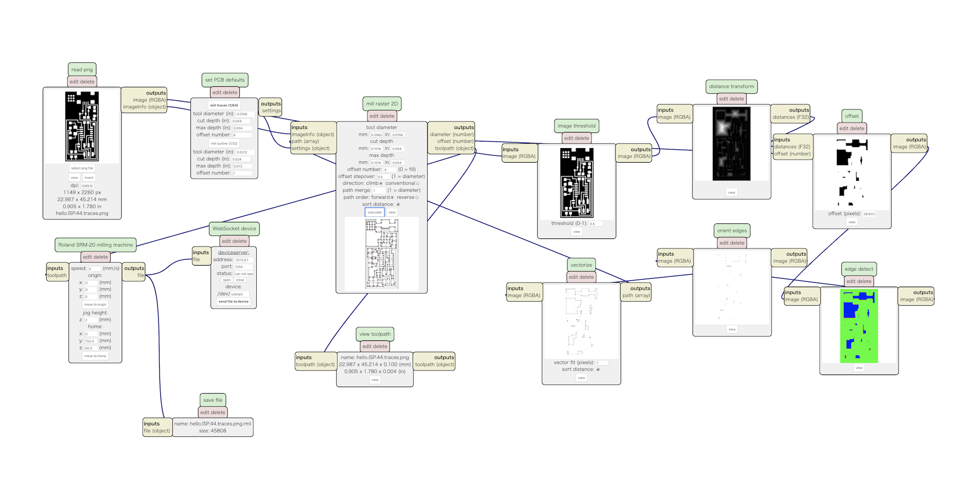
- Read the trace png file in “read png” panel. I checked the resolution (dpi) is enough and the width and height are correct.
- On the “set PCB defaults” Panel, I pushed “mill trace (1/64)”, the tool diameter to milling the traced circuit.
- Also, I added the panel of “save file” to export the rml files.
The screen of mods is here:
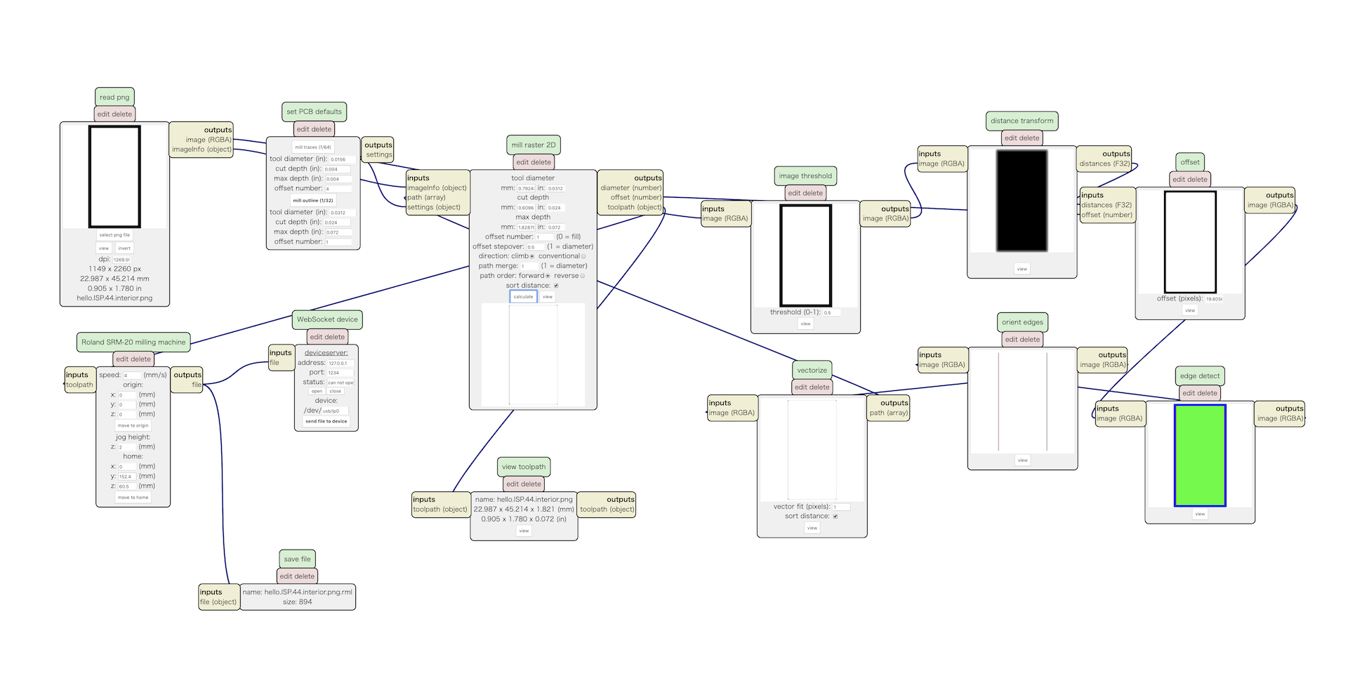
Also, I downloaded the board outline file from here. Then, also generated rml file by using mods.
The important setting for making outline board are same with reading trace file. “set PCB defaults” Panel, I pushed “mill trace (1/32)”, the tool diameter to milling cutting the board.
The mods screen is here:
Milling by Roland SRM-20
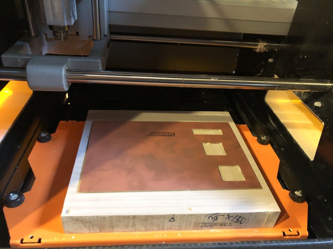
Here are FabLab Kamakura’s Roland SRM-20:
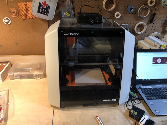
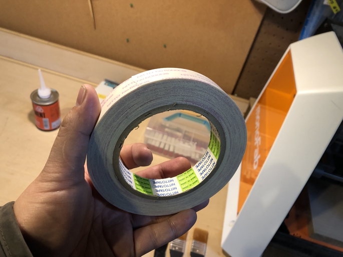
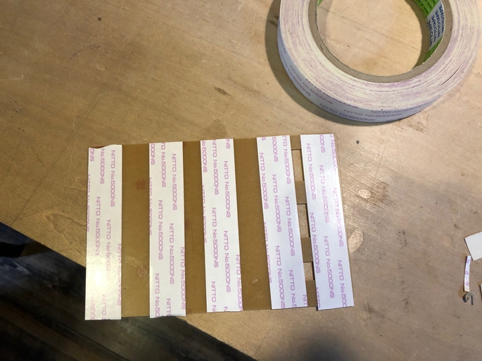
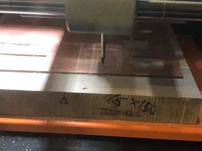
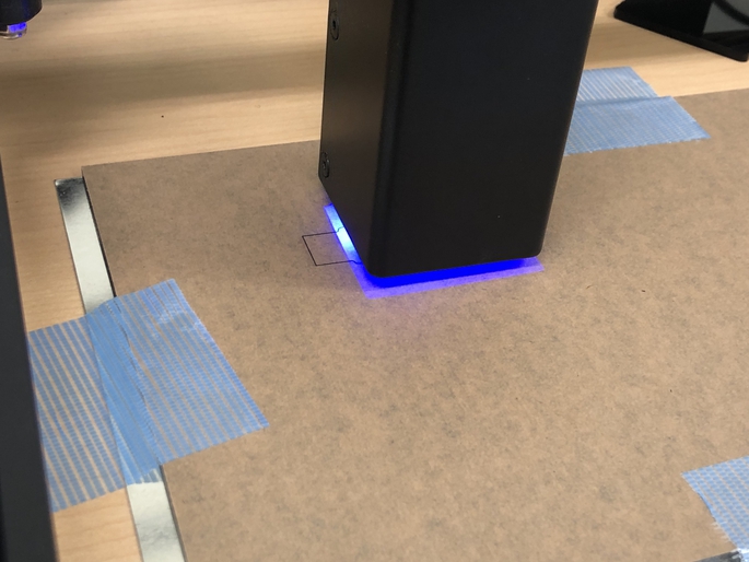
First, I put the PCB board in the SRM-20. I taped down the board in order to keep it flat with “sacrificial board”.
Next, I set 1/64 endmill and adjust X, Y, Z original point controlling from “VPanel for SRM-20”.
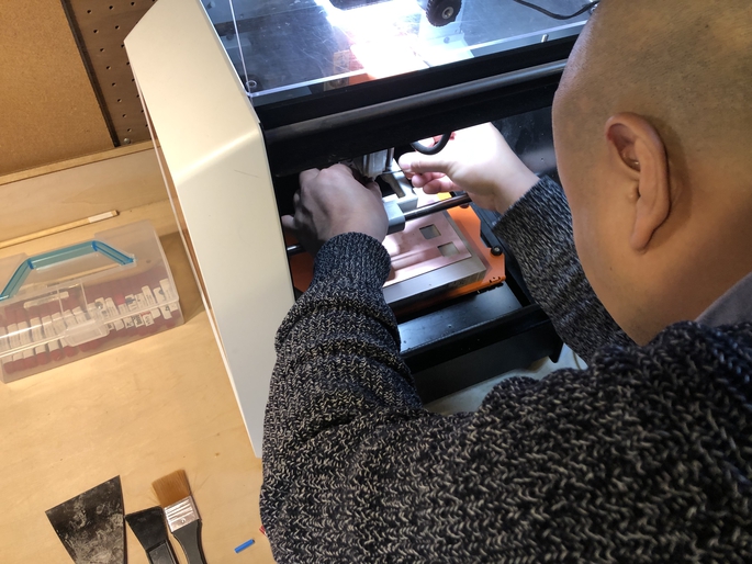
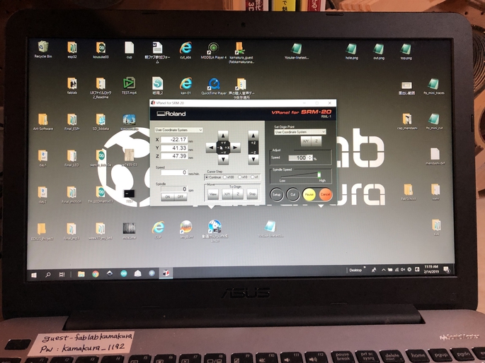
And, I moved the endmill posion to the original.
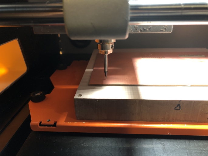
Then, read the rml file of trace file and start the milling.
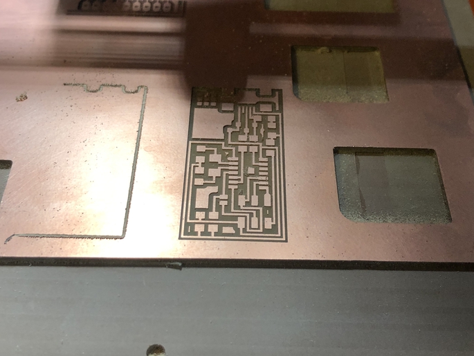
I changed the endmill to 1/32 size, and mill the outline of the board.
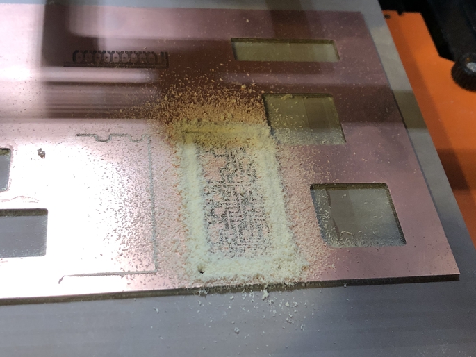
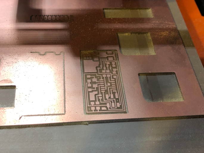
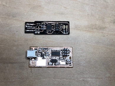
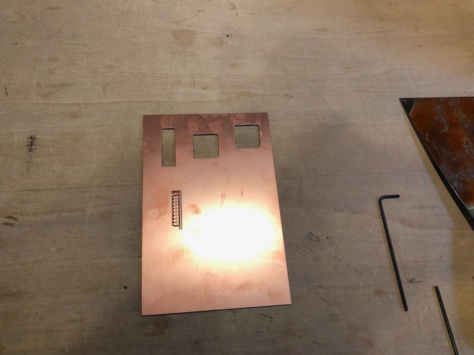
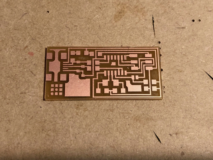
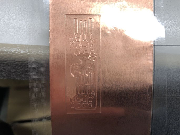
Finally, I milled the FabISP board well.
Soldering
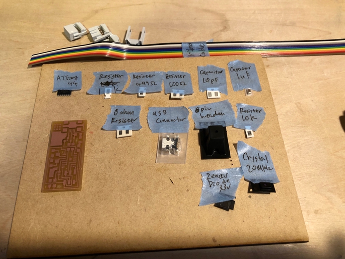
With following the tutorial page, I choosed the parts as below:
- 1 ATTiny 44 microcontroller
- 1 Capacitor 1uF
- 2 Capacitor 10 pF
- 2 Resistor 100 ohm
- 1 Resistor 499 ohm
- 1 Resistor 1K ohm
- 1 Resistor 10K
- one 6 pin header
- 1 USB connector
- 2 jumpers - 0 ohm resistors
- 1 Crystal 20MHz
- two Zener Diode 3.3 V
- one usb mini cable
- one ribbon cable
- two 6 pin connectors
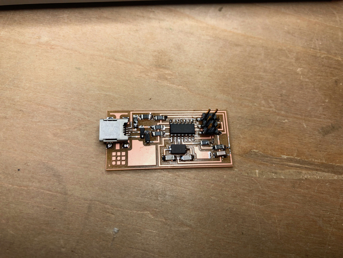
Then, soldered each parts into my FabISP board.
Writing the firmware: 1st challenge
I am using Macbook Pro 15 inch (OSX Mojave). So, first I installed Crosspack AVR. (I have already Xcode and make).
And, I downloaded FabISP Firmware and unzip it at my home folder.
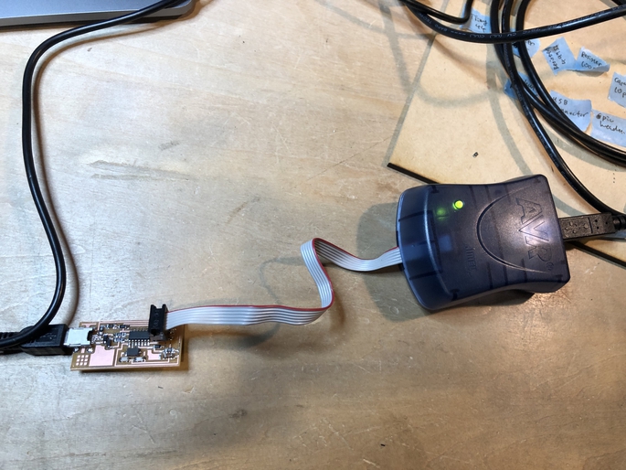
Then, I connected ATAVRISP2 programmer to my FabISP.
Edited Makefile, just comment out the setting for writing by usptiny programmer, then uncommented the setting for wrting by avrisp2.
#AVRDUDE = avrdude -c usbtiny -p $(DEVICE) # edit this line for your programmer
AVRDUDE = avrdude -c avrisp2 -P usb -p $(DEVICE) # edit this line for your programmer
OK, it’s time to write into my FabISP… first, I typed the command “make clean”. And, I could see the following message (means “make clean” process well done.)
rm -f main.hex main.lst main.obj main.cof main.list main.map main.eep.hex main.elf *.o usbdrv/*.o main.s usbdrv/oddebug.s usbdrv/usbdrv.s
And, I typed the command “make hex”, and I checked the main.hex file is found out.
avr-gcc -Wall -Os -DF_CPU=20000000   -Iusbdrv -I. -DDEBUG_LEVEL=0 -mmcu=attiny44 -c usbdrv/usbdrv.c -o usbdrv/usbdrv.o
avr-gcc -Wall -Os -DF_CPU=20000000   -Iusbdrv -I. -DDEBUG_LEVEL=0 -mmcu=attiny44 -x assembler-with-cpp -c usbdrv/usbdrvasm.S -o usbdrv/usbdrvasm.o
avr-gcc -Wall -Os -DF_CPU=20000000   -Iusbdrv -I. -DDEBUG_LEVEL=0 -mmcu=attiny44 -c usbdrv/oddebug.c -o usbdrv/oddebug.o
avr-gcc -Wall -Os -DF_CPU=20000000   -Iusbdrv -I. -DDEBUG_LEVEL=0 -mmcu=attiny44 -c main.c -o main.o
main.c:88:13: warning: always_inline function might not be inlinable [-Wattributes]
 static void delay ( void )
             ^
avr-gcc -Wall -Os -DF_CPU=20000000   -Iusbdrv -I. -DDEBUG_LEVEL=0 -mmcu=attiny44 -o main.elf usbdrv/usbdrv.o usbdrv/usbdrvasm.o usbdrv/oddebug.o main.o
rm -f main.hex main.eep.hex
avr-objcopy -j .text -j .data -O ihex main.elf main.hex
avr-size main.hex
   text    data     bss     dec     hex filename
      0    2002       0    2002     7d2 main.hex
OK, I typed the command “make fuse”…
avrdude -c avrisp2 -P usb -p attiny44  -U hfuse:w:0xDF:m -U lfuse:w:0xFF:m
avrdude: usbdev_open(): did not find any USB device "usb"
make: *** [fuse] Error 1
..... I could not write…
The problem
I could find out problems from the instructors advices. There are two problems in my board and both are totally hardware problem.
Crystal
I used lab’s 20Mhz Crystal, but instructors find out this crystal did not oscillate well. So, I changed two 10pF capaciters to 18pF one.
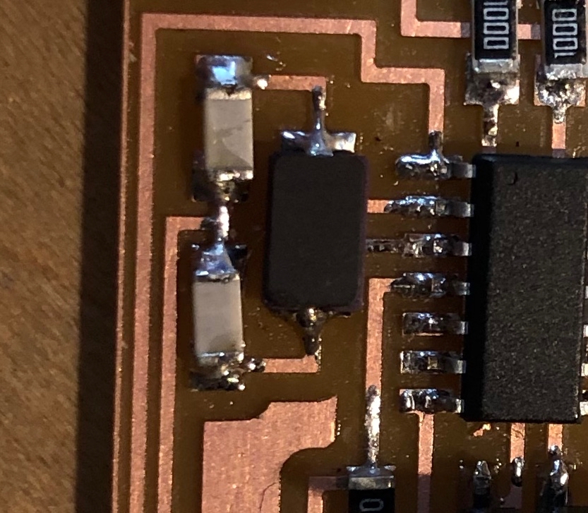
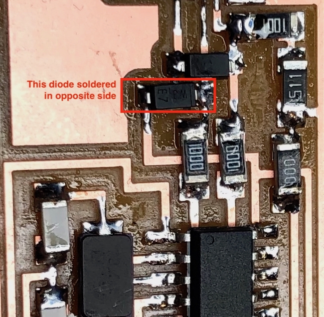
Diodes
Instructors found out one diode soldered in oppsit side. The cathode of the diode should be right, according to the circuit diagram. But, in my board, one diode’s cathode soldered in left side.
Note: Finally, I could write the firmware into my FabISP. But, It tooks about 3 hours to complete this process… I am great thanks to Mr. Yamamoto (Fab Lab Kamakura’s special support and electronics guru).
Writing Firmware: 2nd challenge
I fixed both hardware mistakes, then tried to write a firmware, again.
$ make fuse

avrdude -c avrisp2 -P usb -p attiny44  -U hfuse:w:0xDF:m -U lfuse:w:0xFF:m

avrdude: AVR device initialized and ready to accept instructions

Reading | ################################################## | 100% 0.00s

avrdude: Device signature = 0x1e9207
avrdude: reading input file "0xDF"
avrdude: writing hfuse (1 bytes):

Writing | ################################################## | 100% 0.00s

avrdude: 1 bytes of hfuse written
avrdude: verifying hfuse memory against 0xDF:
avrdude: load data hfuse data from input file 0xDF:
avrdude: input file 0xDF contains 1 bytes
avrdude: reading on-chip hfuse data:

Reading | ################################################## | 100% 0.00s

avrdude: verifying ...
avrdude: 1 bytes of hfuse verified
avrdude: reading input file "0xFF"
avrdude: writing lfuse (1 bytes):

Writing | ################################################## | 100% 0.00s

avrdude: 1 bytes of lfuse written
avrdude: verifying lfuse memory against 0xFF:
avrdude: load data lfuse data from input file 0xFF:
avrdude: input file 0xFF contains 1 bytes
avrdude: reading on-chip lfuse data:

Reading | ################################################## | 100% 0.00s

avrdude: verifying ...
avrdude: 1 bytes of lfuse verified

avrdude: safemode: Verify error - unable to read hfuse properly. Programmer may not be reliable.
avrdude: safemode: Fuses OK (H:FF, E:DF, L:FF)

avrdude done.  Thank you.
It looks succeeded.
Then, I programmed it by sending command “make program”
$ make program
avrdude -c avrisp2 -P usb -p attiny44  -U flash:w:main.hex:i

avrdude: AVR device initialized and ready to accept instructions

Reading | ################################################## | 100% 0.00s

avrdude: Device signature = 0x1e9207
avrdude: NOTE: "flash" memory has been specified, an erase cycle will be performed
         To disable this feature, specify the -D option.
avrdude: erasing chip
avrdude: reading input file "main.hex"
avrdude: writing flash (2002 bytes):

Writing | ################################################## | 100% 0.69s

avrdude: 2002 bytes of flash written
avrdude: verifying flash memory against main.hex:
avrdude: load data flash data from input file main.hex:
avrdude: input file main.hex contains 2002 bytes
avrdude: reading on-chip flash data:

Reading | ################################################## | 100% 0.62s

avrdude: verifying ...
avrdude: 2002 bytes of flash verified

avrdude: safemode: Fuses OK (H:FF, E:DF, L:FF)

avrdude done.  Thank you.

avrdude -c avrisp2 -P usb -p attiny44  -U hfuse:w:0xDF:m -U lfuse:w:0xFF:m

avrdude: AVR device initialized and ready to accept instructions

Reading | ################################################## | 100% 0.00s

avrdude: Device signature = 0x1e9207
avrdude: reading input file "0xDF"
avrdude: writing hfuse (1 bytes):

Writing | ################################################## | 100% 0.00s

avrdude: 1 bytes of hfuse written
avrdude: verifying hfuse memory against 0xDF:
avrdude: load data hfuse data from input file 0xDF:
avrdude: input file 0xDF contains 1 bytes
avrdude: reading on-chip hfuse data:

Reading | ################################################## | 100% 0.00s

avrdude: verifying ...
avrdude: 1 bytes of hfuse verified
avrdude: reading input file "0xFF"
avrdude: writing lfuse (1 bytes):

Writing | ################################################## | 100% 0.00s

avrdude: 1 bytes of lfuse written
avrdude: verifying lfuse memory against 0xFF:
avrdude: load data lfuse data from input file 0xFF:
avrdude: input file 0xFF contains 1 bytes
avrdude: reading on-chip lfuse data:

Reading | ################################################## | 100% 0.00s

avrdude: verifying ...
avrdude: 1 bytes of lfuse verified

avrdude: safemode: Fuses OK (H:FF, E:DF, L:FF)

avrdude done.  Thank you.
Well, done.
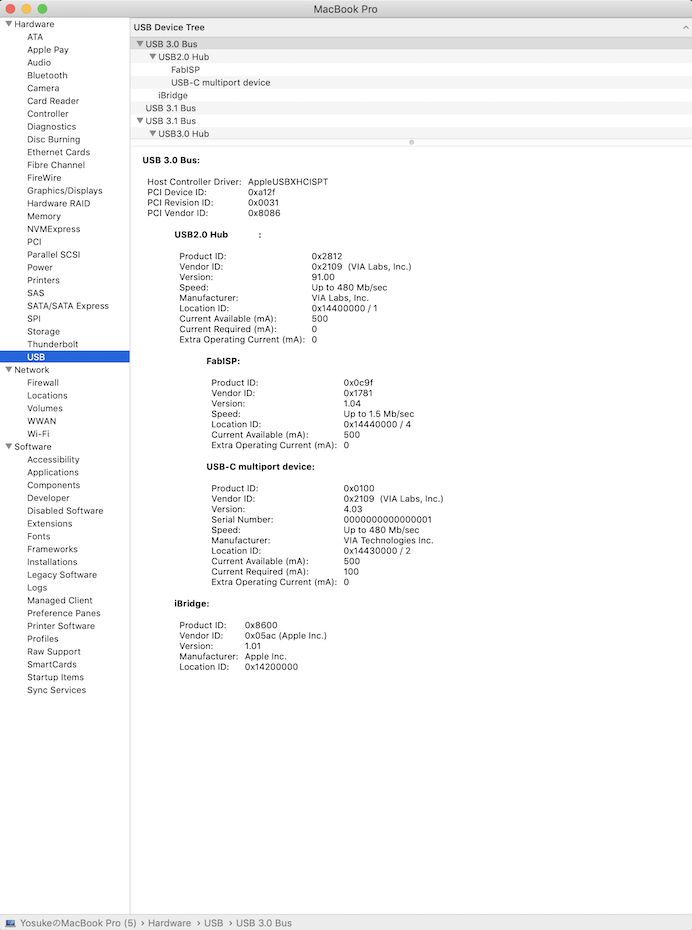
Now I removed the jumper, and tried to conect to the PC via USB 2.0 cable. Finall, my Macbook Pro found out my first FabISP !!!
Making FabTinyISP (by cutting)
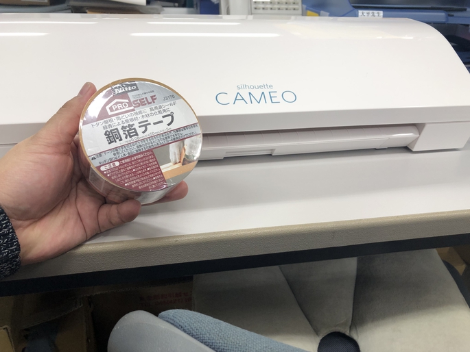
I also want to try making flexible PCB.
Luckly, I got my own vinyl cutter (Silhuetto CAMEO 3) in my unviersity. Also, I got a cooper tape. So, I tried to make FabTinyISP by cutting process.
1st Challenge
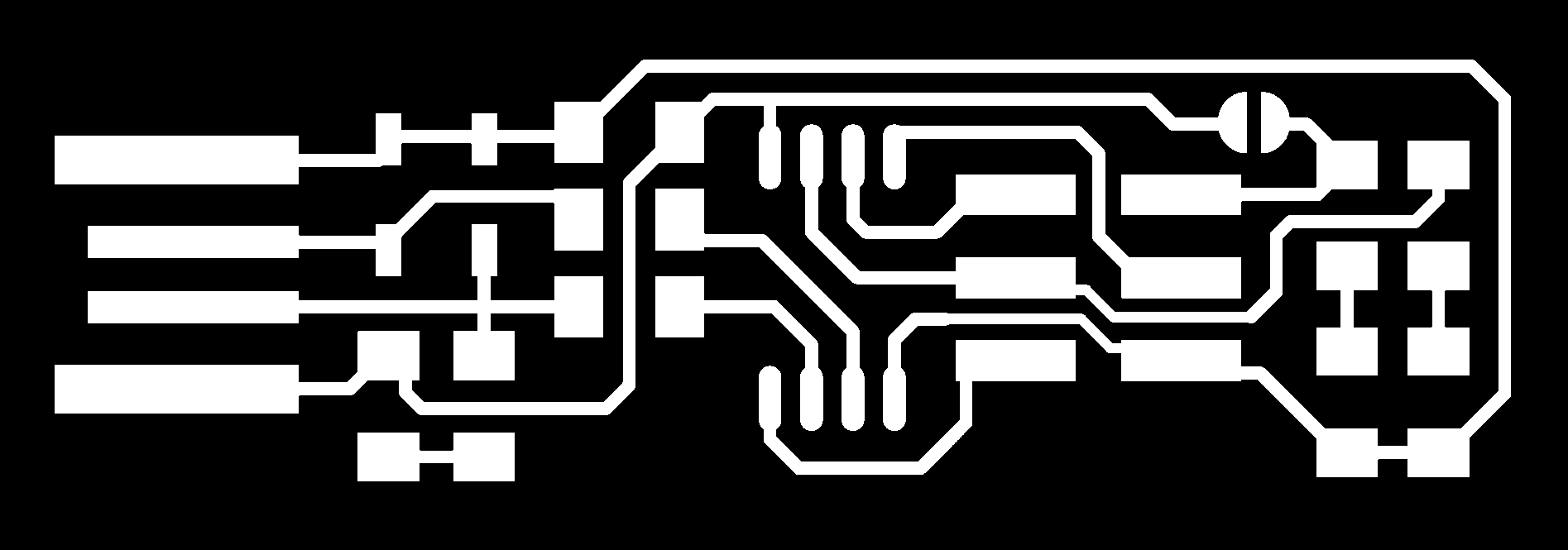
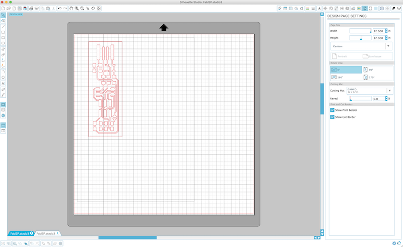
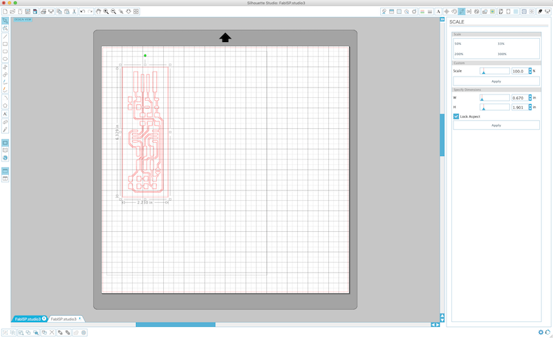
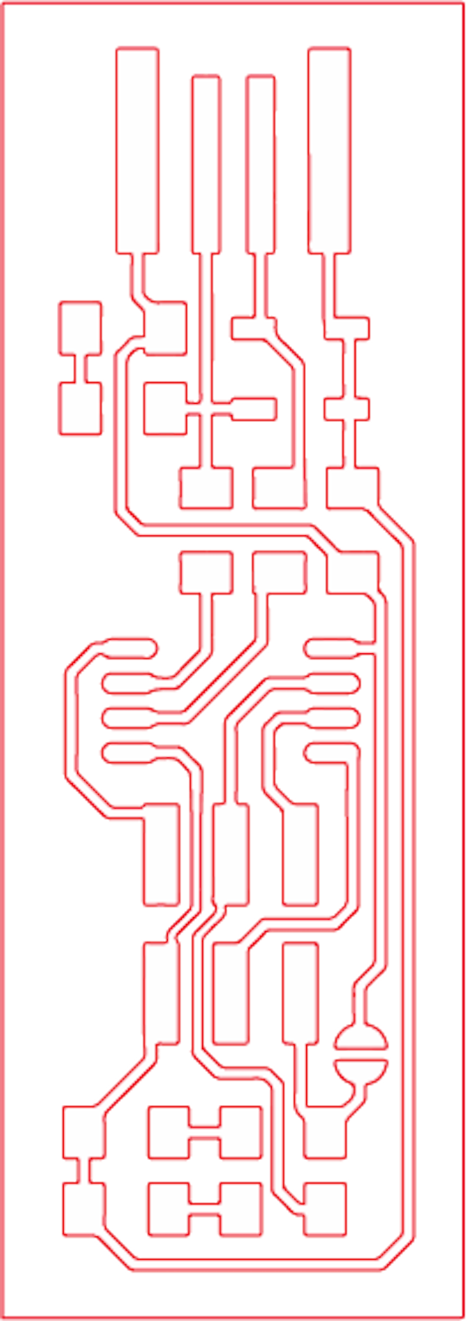
First, I installed Silhuette Studio to make a data for cutting and controlled CAMEO from my PC. Then, I import the png file that’s tracing circuit of FabTinyISP.
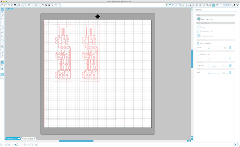
Then, trace the path for cutting. Move to “TRACE” tab, and “Select Trace Area”. Then, enclose the circuit board as trace area and select “trace”.
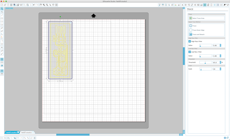
I can see original and traced path both on the screen. Remove original one.
Then, adjisting scale of the cutting path. Choose “SCALE” tab and set width: 0.67 inch and height: 1.9 inch (17.09mm x 48.34mm).
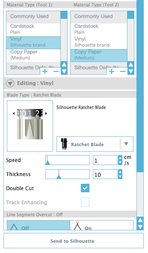
Then, set cutting parameter. Move to “CUT SETTING” and choose “cut”.
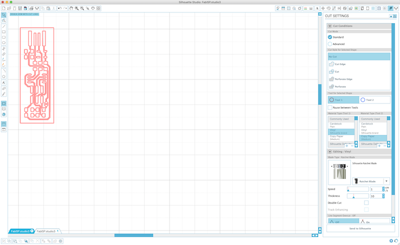
Cutting parameters. This is important part and I set for my Silhuetter CAMEO 3 as following....
| Parameters | Values |
|---|---|
| Material Type | Vinyl (Silhuette Brade) |
| Silhuette Rachet Blade | 1 |
| Speed | 1 cm |
| Thickness | 10 |
| Double Cut | On |
After finished setting the parameters, I started cutting.
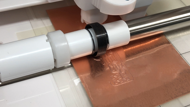
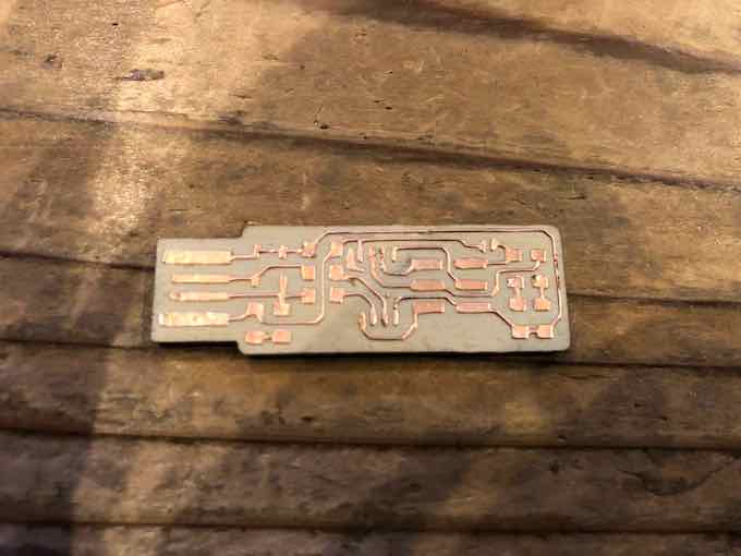
This time, I peeled transfer sheet on both front and back of cooper tape in order not to come off from the base sheet of the cutter. So, fortunally, I could cut the circuit well.
Then, I need the base to peel the circuit. I used acrylic resin board (black color) for it. I downloaded the outline file of FabTinyISP, and cut it with my Cheap (but sometime useful) laser cutter called “Fabool Laser Mini”.
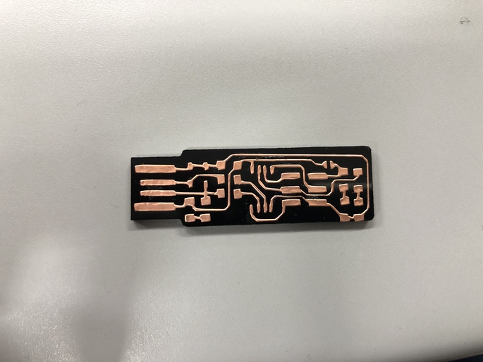
After cutting acrylic resin board in a outline of the FabTinyISP, I peeled cutted circuit on it. It looks very cool…
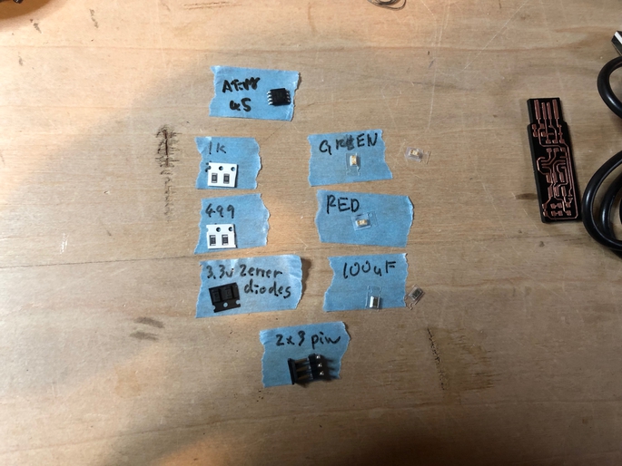
Then, with following the FabTinyISP tutorial page, I soldered the following parts on my circuit board.
- 1x ATtiny45 or ATtiny85
- 2x 1kΩ resistors
- 2x 510Ω resisters (our lab didn’t have 499Ω resistors. So, I replaced it to 510 resisters).
- 2x 100Ω resisters (our lab didn’t have 49Ω resistors. So, I replaced it to 100Ω resisters).
- 2x 3.3v zener diodes
- 1x red LED
- 1x green LED
- 1x 100nF capacitor
- 1x 2x3 pin header
Soldering was finished. In my opinion, soldering on acrylic resin board are very difficult because it is easy to melt. Also, gule of circuit board are easy to come off when soldering. This time, I chose acrylic board just a reason that would looks nice (and, firstly, I wanted to use clear acrylic board, but my laser cutter, Fabool Laser Mini, couldn’t cut the clear board. So, I chose black one). As a 2nd challenge, I am trying to use other useful board for peeling cooper tape circuit.
Anyway, I could soldered all parts on my FabTinyISP circuit board.
Finally, I tried to write the firmware of FabTinyISP. But, I haven’t succeeded, yet. The board itself are electrified, but the AVRISP2 writer that connected to my PC does not recgnized my FabTinyISP, and the following error appeard when I type command “make flash”.
avrdude -p attiny45 -c usbtiny -P usb -e \
        -U flash:w:fts_firmware.hex
avrdude: Error: Could not find USBtiny device (0x1781/0xc9f)

avrdude done.  Thank you.

make: *** [flash] Error 1
My instructor checked the soldering and conditions of circuit board, and it looks fine. Then, I tried to “make flash” again, and one time, I found the following succeeded message.
But, I tried to do next step, “make fuses” command, the same error appeard.....
I guess the problem would be the USB connector, and that part became a little bit broken. So, now I am trying to restart to cut the circuit again with choosing suitable material for base.
2nd Challenge
On April 21, 2019.
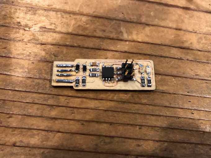
After finished a couple of assignments for electronics, I come back and decided to try again. In the 2nd try, I changed the material of base for the circuit board from acryl to wood.
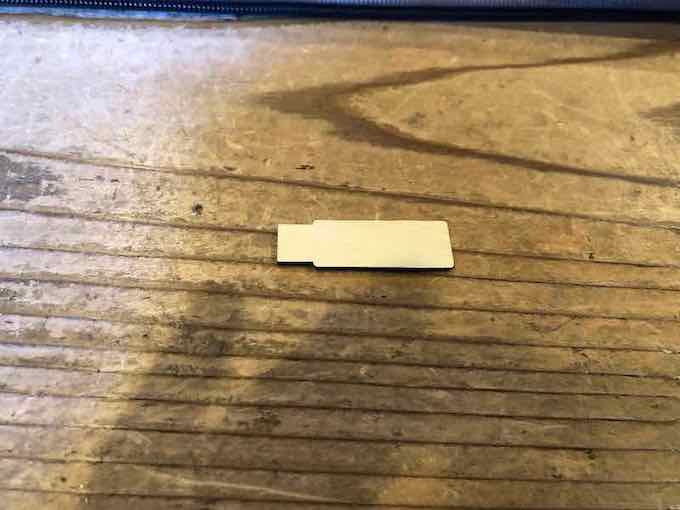
Then, setting cooper tape again, and import FabTinyISP trace file into Silhuette Studio.... The same way with 1st challange.
And, start for cutting.
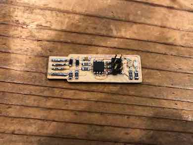
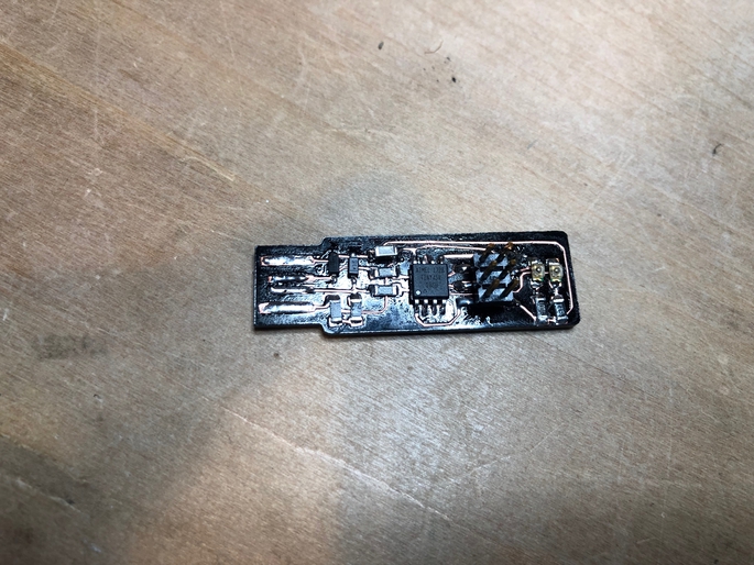
Then, pasted cooper circuit on the wood board.
Solidering parts.... this time it is not so difficult for solidering.
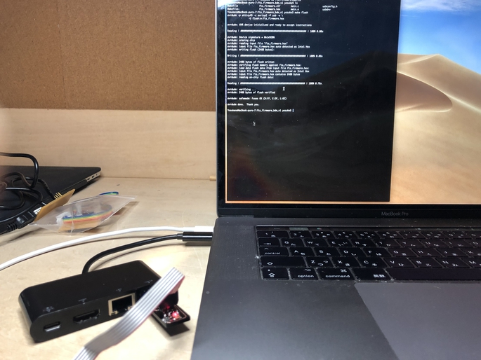
With following Tutorial page for FabTinyISP, I tried to write firmware into the board.
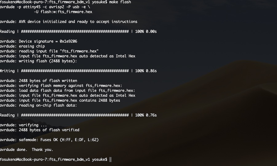
First, I did “make flash”.
$ make flash
avrdude -p attiny45 -c avrisp2 -P usb -e \
    -U flash:w:fts_firmware.hex

avrdude: AVR device initialized and ready to accept instructions

Reading | ################################################## | 100% 0.00s

avrdude: Device signature = 0x1e9206 (probably t45)
avrdude: erasing chip
avrdude: reading input file "fts_firmware.hex"
avrdude: input file fts_firmware.hex auto detected as Intel Hex
avrdude: writing flash (2470 bytes):

Writing | ################################################## | 100% 0.86s

avrdude: 2470 bytes of flash written
avrdude: verifying flash memory against fts_firmware.hex:
avrdude: load data flash data from input file fts_firmware.hex:
avrdude: input file fts_firmware.hex auto detected as Intel Hex
avrdude: input file fts_firmware.hex contains 2470 bytes
avrdude: reading on-chip flash data:

Reading | ################################################## | 100% 0.74s

avrdude: verifying ...
avrdude: 2470 bytes of flash verified

avrdude: safemode: Fuses OK (E:FF, H:DF, L:62)

avrdude done.  Thank you.
It looks succeeded. Then, in the next step, do “make fuses”… That is the part I could not do in the 1st challenge.
$ make fuses
avrdude -p attiny45 -c avrisp2 -P usb \
    -U lfuse:w:0xE1:m -U hfuse:w:0xDD:m \
    -U efuse:w:0xFF:m

avrdude: AVR device initialized and ready to accept instructions

Reading | ################################################## | 100% 0.00s

avrdude: Device signature = 0x1e9206 (probably t45)
avrdude: reading input file "0xE1"
avrdude: writing lfuse (1 bytes):

Writing | ################################################## | 100% 0.01s

avrdude: 1 bytes of lfuse written
avrdude: verifying lfuse memory against 0xE1:
avrdude: load data lfuse data from input file 0xE1:
avrdude: input file 0xE1 contains 1 bytes
avrdude: reading on-chip lfuse data:

Reading | ################################################## | 100% 0.00s

avrdude: verifying ...
avrdude: 1 bytes of lfuse verified
avrdude: reading input file "0xDD"
avrdude: writing hfuse (1 bytes):

Writing | ################################################## | 100% 0.01s

avrdude: 1 bytes of hfuse written
avrdude: verifying hfuse memory against 0xDD:
avrdude: load data hfuse data from input file 0xDD:
avrdude: input file 0xDD contains 1 bytes
avrdude: reading on-chip hfuse data:

Reading | ################################################## | 100% 0.00s

avrdude: verifying ...
avrdude: 1 bytes of hfuse verified
avrdude: reading input file "0xFF"
avrdude: writing efuse (1 bytes):

Writing | ################################################## | 100% 0.01s

avrdude: 1 bytes of efuse written
avrdude: verifying efuse memory against 0xFF:
avrdude: load data efuse data from input file 0xFF:
avrdude: input file 0xFF contains 1 bytes
avrdude: reading on-chip efuse data:

Reading | ################################################## | 100% 0.00s

avrdude: verifying ...
avrdude: 1 bytes of efuse verified

avrdude: safemode: Fuses OK (E:FF, H:DD, L:E1)

avrdude done.  Thank you.
Well, done. So, I checked whether it would be recognized as a usb devices on my PC.
$ lsusb
Bus 002 Device 001: ID 1d6b:0003 Linux Foundation 3.0 root hub
Bus 001 Device 004: ID 045e:07bf Microsoft Corp.
Bus 001 Device 003: ID 045e:07be Microsoft Corp.
Bus 001 Device 005: ID 1286:204b Marvell Semiconductor, Inc.
Bus 001 Device 002: ID 045e:09c1 Microsoft Corp.
Bus 001 Device 046: ID 1781:0c9f Multiple Vendors USBtiny
Bus 001 Device 045: ID 1a40:0101 Terminus Technology Inc. Hub
Bus 001 Device 001: ID 1d6b:0002 Linux Foundation 2.0 root hub
Yeah, the board recognized as a usb devices. Now, get ready to blow the Reset Fuse.
$ make rstdisbl
avrdude -p attiny45 -c avrisp2 -P usb \
    -U lfuse:w:0xE1:m -U hfuse:w:0x5D:m \
    -U efuse:w:0xFF:m

avrdude: AVR device initialized and ready to accept instructions

Reading | ################################################## | 100% 0.00s

avrdude: Device signature = 0x1e9206 (probably t45)
avrdude: reading input file "0xE1"
avrdude: writing lfuse (1 bytes):

Writing | ################################################## | 100% 0.01s

avrdude: 1 bytes of lfuse written
avrdude: verifying lfuse memory against 0xE1:
avrdude: load data lfuse data from input file 0xE1:
avrdude: input file 0xE1 contains 1 bytes
avrdude: reading on-chip lfuse data:

Reading | ################################################## | 100% 0.00s

avrdude: verifying ...
avrdude: 1 bytes of lfuse verified
avrdude: reading input file "0x5D"
avrdude: writing hfuse (1 bytes):

Writing | ################################################## | 100% 0.01s

avrdude: 1 bytes of hfuse written
avrdude: verifying hfuse memory against 0x5D:
avrdude: load data hfuse data from input file 0x5D:
avrdude: input file 0x5D contains 1 bytes
avrdude: reading on-chip hfuse data:

Reading | ################################################## | 100% 0.00s

avrdude: verifying ...
avrdude: 1 bytes of hfuse verified
avrdude: reading input file "0xFF"
avrdude: writing efuse (1 bytes):

Writing | ################################################## | 100% 0.01s

avrdude: 1 bytes of efuse written
avrdude: verifying efuse memory against 0xFF:
avrdude: load data efuse data from input file 0xFF:
avrdude: input file 0xFF contains 1 bytes
avrdude: reading on-chip efuse data:

Reading | ################################################## | 100% 0.00s

avrdude: verifying ...
avrdude: 1 bytes of efuse verified

avrdude: safemode: Fuses OK (E:FF, H:5D, L:E1)

avrdude done.  Thank you.
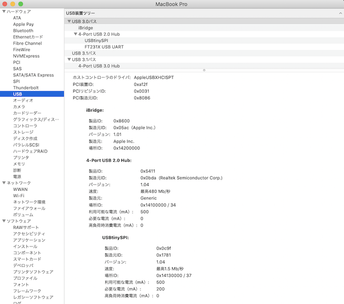
And, cutting jumper.... It is completed. Checking on my Macbook Pro, I could find it as “USB Tiny SPI”.
Observations
This week’s topic “electornics production”, and other related topics “electronics design” and “embedded programming” (and any other topics relating to electronics works) are one of the most I really want to learn and master in Fab Academy (of course, other topics also want to master). So, I really enjoyed this week assignment well.
Prof. Neil said this week are “leaset creative but most useful”. Basically, I agree with his opinion well, especially the words “most useful”. On the other hand, through experiencing cutting process to make flexible circuit board, I also thought electronics production would be more creative when we choose cutting process because it makes looking nice or cool by combining the materials and shapes of the board and circuit, as shown in the works by Honghao Deng’s cube circuit board and Thomas’s Press-fit Construction works.