Tracking Page of Final Project
About My final project, Please also see:
This page describe what I did in the final project (tracking my works). The following is the task for completing my final project
- Studying Robotics
- Mechanism of six legs walking
- Designing and Making Insect Robot
- Computer-Controlled Cutting for Mechanical Parts
- 3D Printing for Main Body
- Electornics Design with two DC motors (geabox)
- Input Devices modules Design
- Assembling And Finishing
- Remained Tasks and Further Plan
Studying Robotics: Mechanism of walking.
My final project is to make sensing robot which looks like insects. But, these are the most difficult part for me because I am not good at Robotics. So, as a first step of the final project, I begun to study of the basic robo design and mechanism of robot walking with reffering previous works in the labs or conmmercial toy products.
Fab Walker
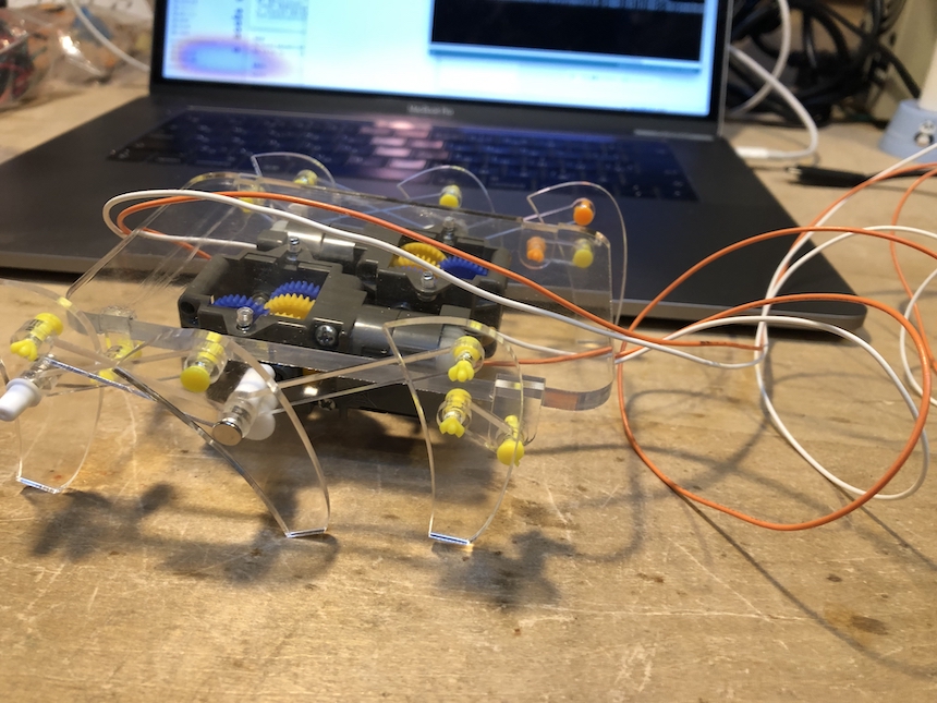
Fab Walker is a fabrication kit for thinking “how does the robot walking better”. It has very simple 4 legs mechanism and controlled by TAMIYA Gerabox and Studuino (an Arduino Compatible board to learn about robotics). I talked with Instructors and they provided me some data of parts to make Fab Walker, then I tried to make it.
Making
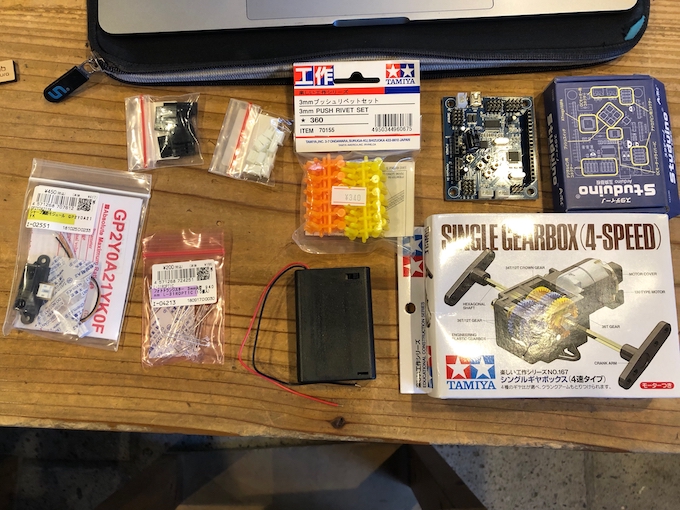
First, I collected equipments which I should buy at the shop. The following is I bought for minimum requirement of Fab Walker. Other screws and spacers are borrowed from the lab inventory.
- Studuino
- TAMIYA Single Gearbox (76167)
- TAMIYA 3mm Push rivet set
- IR Distance Sensor
- Servo Motor (SG90)
- Light Sensor (PARA LIGHT ELECTRONICS)
- 3 x AA Battery Box
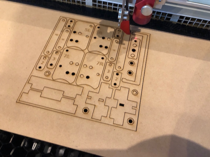
Next, I used lab’s laser cutter for making each parts of Fab Walker.
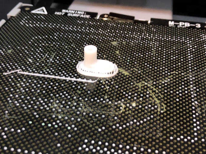
Also, making some 3D parts by 3D printer.
Assembling each parts, and making a body of Fab Walker.
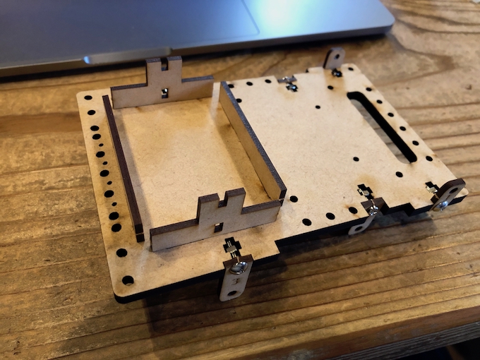
Then, assembling each motors, sensors, studuino and Battery Box.
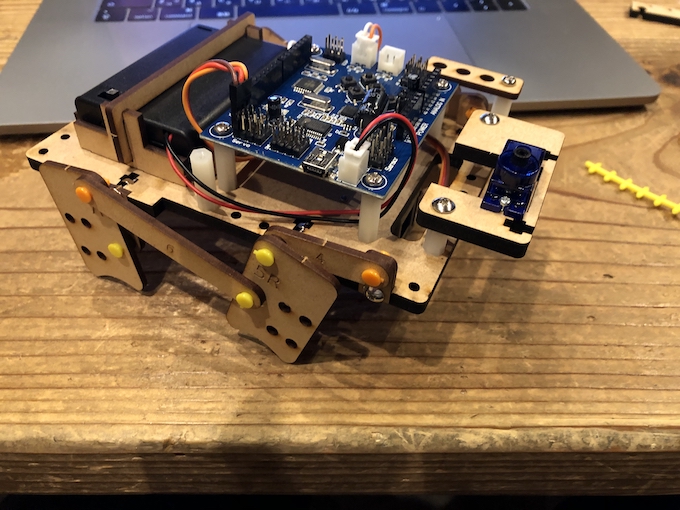
Finally, added IR sensor on the Servo motor.
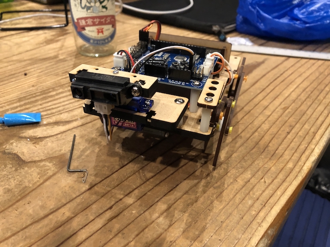
It is finished to make. But, naturally, it still have not work (walk around). I need to install some program into the studuino.
Outcomes from Fab Walker
- It should be divided power supply into microcontroller side and motor driver.
- IR sensor is useful for detecting something like obstacles that robot walking
- one motor is enough to walking around with four legs. But, I’m not sure whether it is enough for 6 legs walking robot.
TAMKYA TOY MODEL
There are some privious works for getting to know how to make insect robots. But, I am seeking simple way to make it. TAMIYA Insect Robots is very useful to learn the mechanism of 6 legs walking. Therefore, I build it and analyze it for studying.
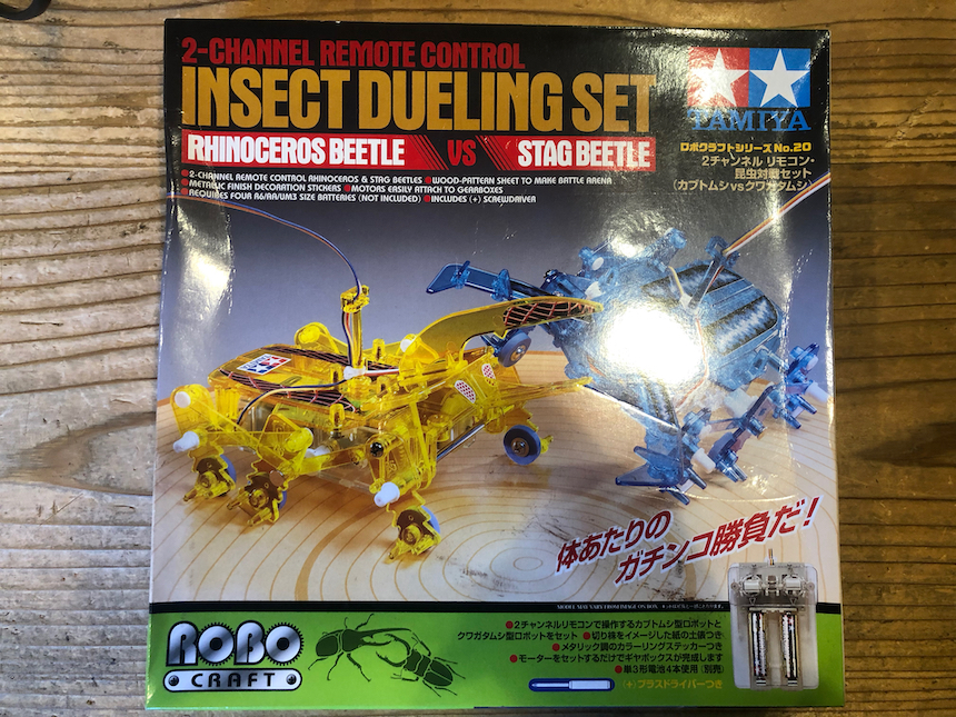
Assembling and Buliding the kit…
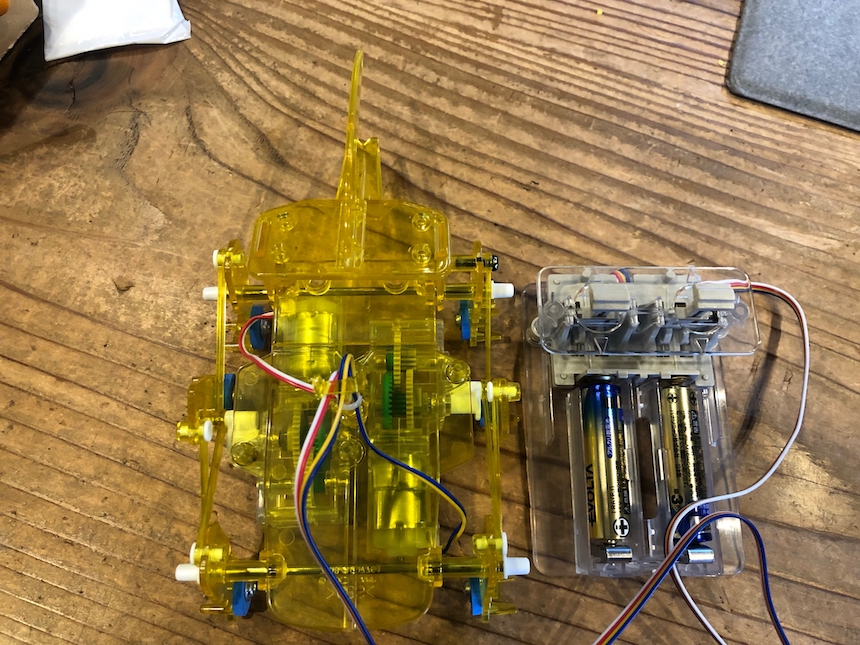
Here are some analysis of this 6 legs robot.
Basic mechanism of 6 legs walking
6 legs walking mechanism consists of two link mechanism of left and right side. Each link mechanism have three legs, center point connect to the motor shaft.
On the left side, there is one connection between the leg in the front and the leg in the middle position. On the other hand, there are two connection between the leg in the middle position and the leg in the back. The connection betweren front and middle should be longer than that between middle and back.
Two DC motors required to work these link mechanism. One motor should be connect to middle of left side, and one should connect to right side.
Controlling 6 legs mechanism
Normal rotation of both two DC motors would go ahead.
Back reverse rotation of Both two DC motors would go back.
Only left side of DC motor works, the robot turn right.
Only right side of DC motor works, the robot turn left.
If one motor rotate normally and another motor rotate in reverse, the robot turn around.
From Robotics Studies.
- I can make 6 legs mechanism of robot with reffering to TAMYNA robot.
- It requires two DC motors and motor drivers to control them.
- Some Sensors is useful to make robots intelligent (but, I am not decided whether I will install this function).
Desiging the mechanical of the Insect Robot and make it.
Well, it’s the time to make a 3D designing and mechanical design of the robot.
First, to make a robot, I bought these commercial parts.
With refferring Fab Walker and Other Insect Robot mechanism, I designed the robot by Autodesk Fusion360.
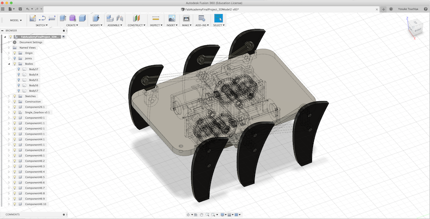
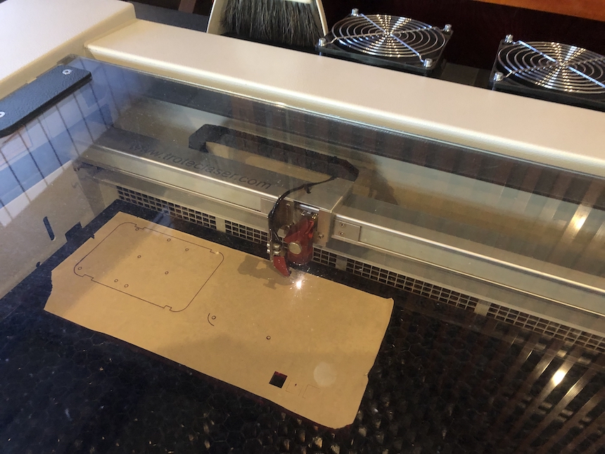
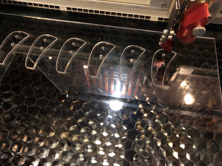
Then, I made data for subtacting (cutting) the model. And, made it with laser cutter.
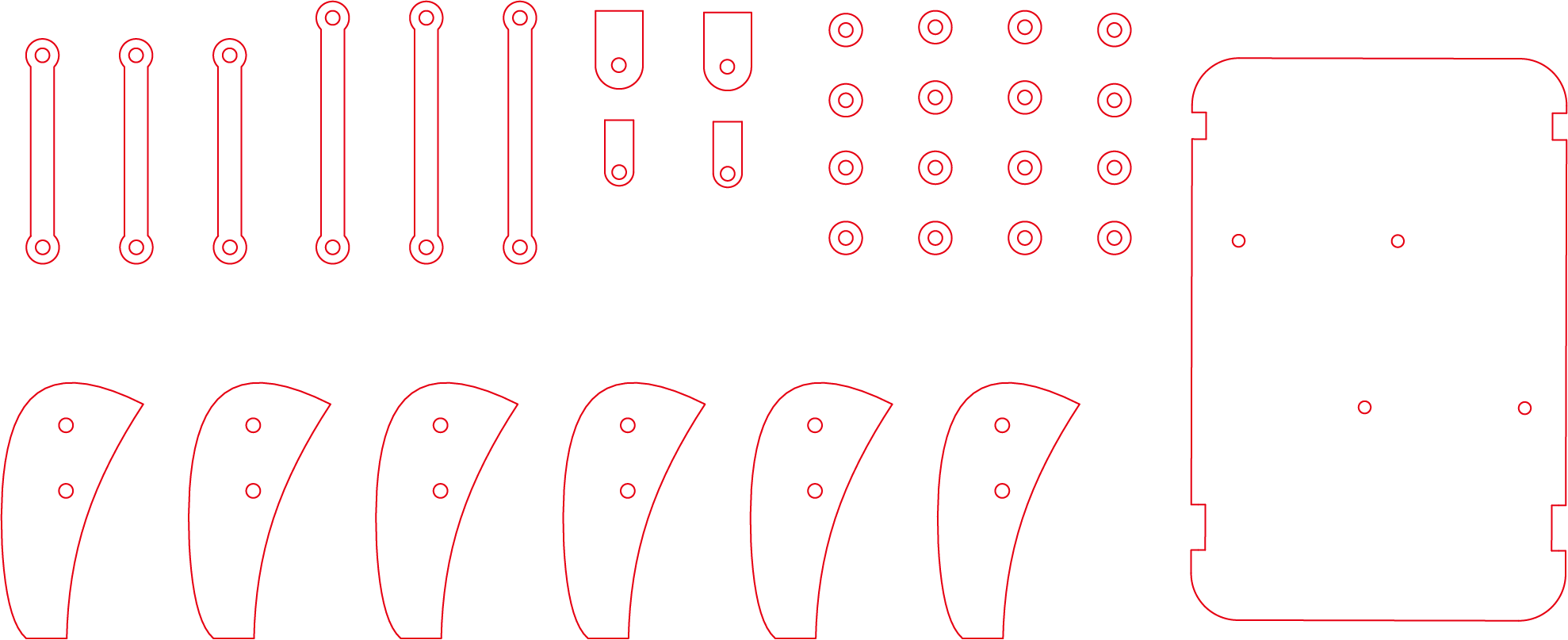
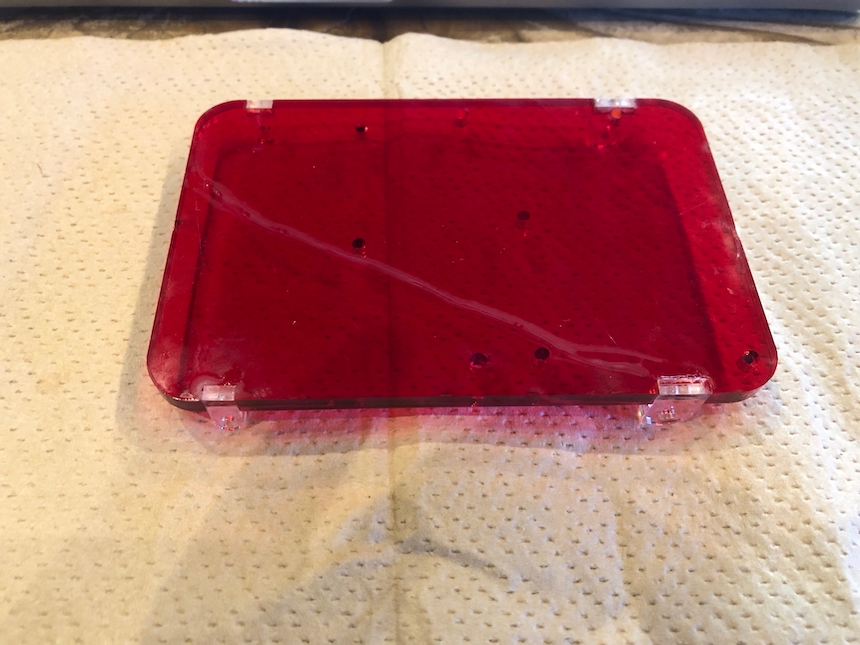
Base of the mechanical parts should be 5mm acrylic board.
Other parts should be 3mm acrylic board.
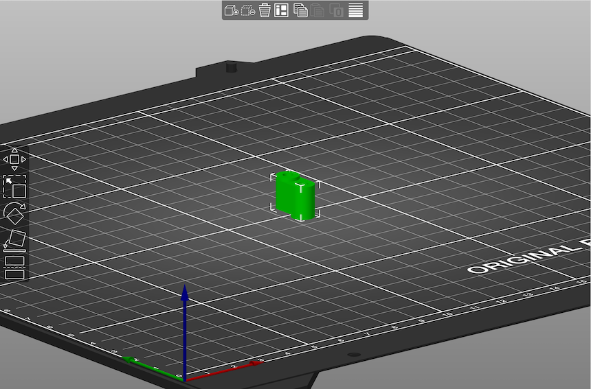
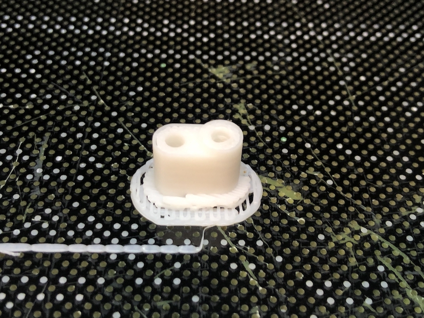
Also, I made some 3D stl data for printing the connector between middle legs and motor shafts.
Then, assembling each parts. For assembling, I used the following joint parts
- TAMIYA 3mm Push rivets (I think it would keep enoough two packs of it).
- motor shaft (it had already included TAMKYA Gearbox)
It looks fine.
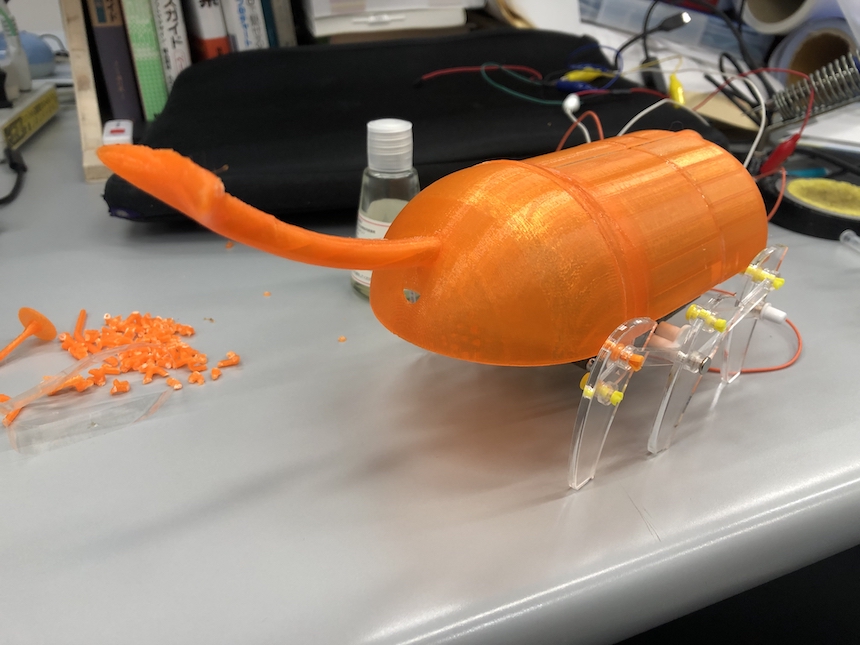
Designing Insect Main Body and Printing it
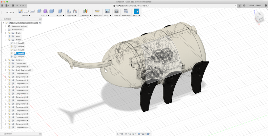
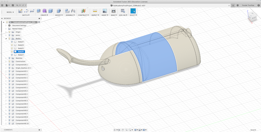
This time, I decided to make insect body with 3D printer. First, I made 3D model of the body with adding on mechanical design of the robot.
Why 3D printing? In the weekly assignment 6 (3D printing and 3D scanning) and assignment 10 (Moldings & Castings), I have learned some of 3D designed model could not make in subtractive approach. In this case (insect body), the backside of the horn and the reverse side of the body (that would be the cover of the mechanical parts) could not make subtractively. So, I choose 3D printing approach to make it. (Reference: Week 6 assignment )
But, the model is too big to 3D print. So, I divided the model into three parts and make each stl files.
Then, reading 3D printer software, make G-Code and set to 3D printer.
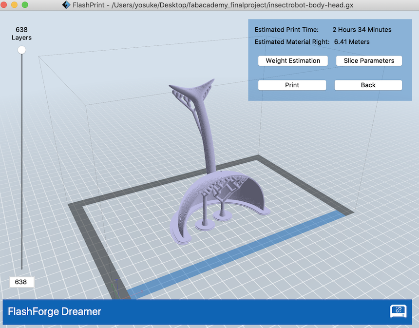
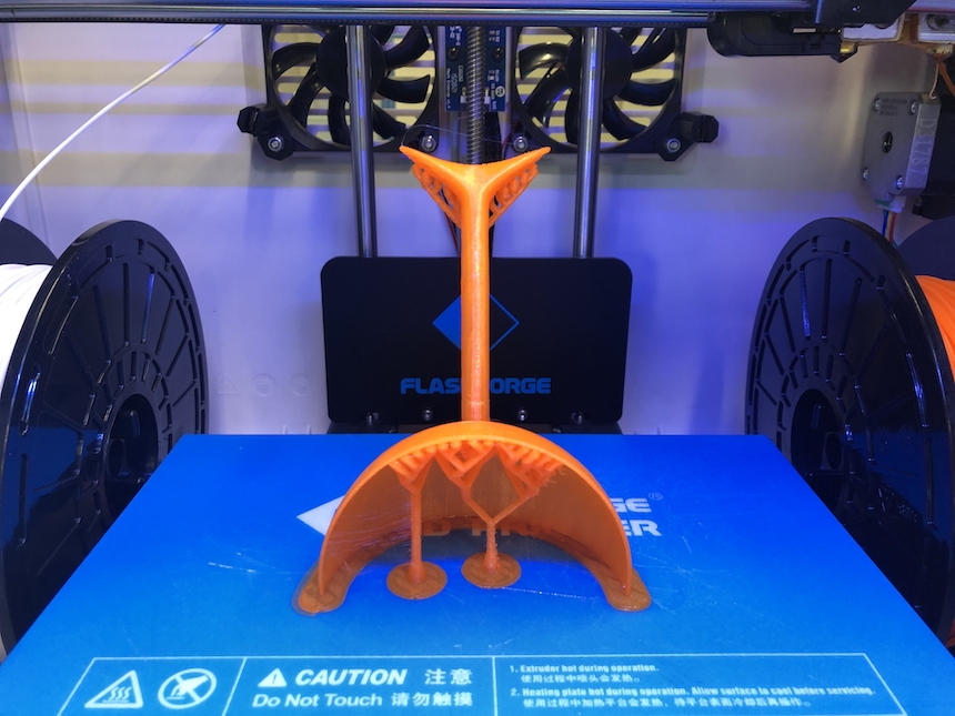
Printed out three parts of Insect Body. But, I have to connect each other into one.
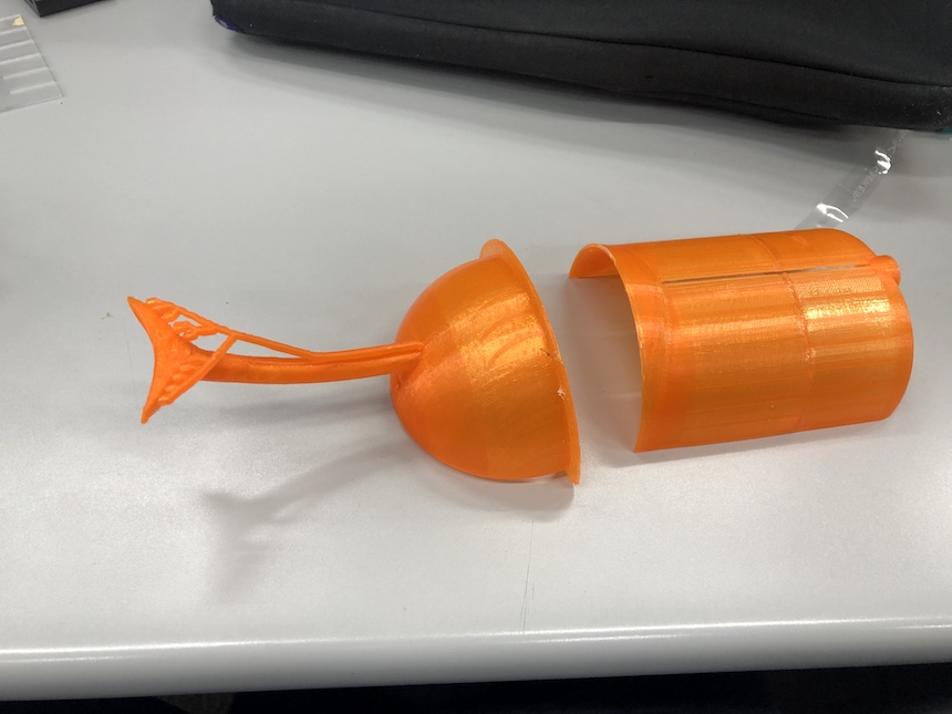
I used an adhesive (normally used for acrylic board) for connecting each parts of the body.
Then, added the connected body to the mechanical base. Looks file.
Electronics Design for Controlling DC motor driver.
Now, I moved to designing the Electronics of the PCB. However, as learned from Output Device week assignment, it should be better to start from breadboard to check how does works designed circuit. In this time, it is better to check how does the DC motor driver works before designing the circuit.(REFERENCE: Assignment 11(Output Devices)).
Checking the DC motor drivers (Toshiba TB6612FNG)
I choosed Toshiba TB6612FNG as a DC motor driver. This motor driver control two dc motor driver at the same time. It would be suitable for controlling 6 legs mechanism that I designed.
The datasheet of this motor driver could see here. Toshiba TB6612FNG have 24 pins and the features of each pins are as follow.
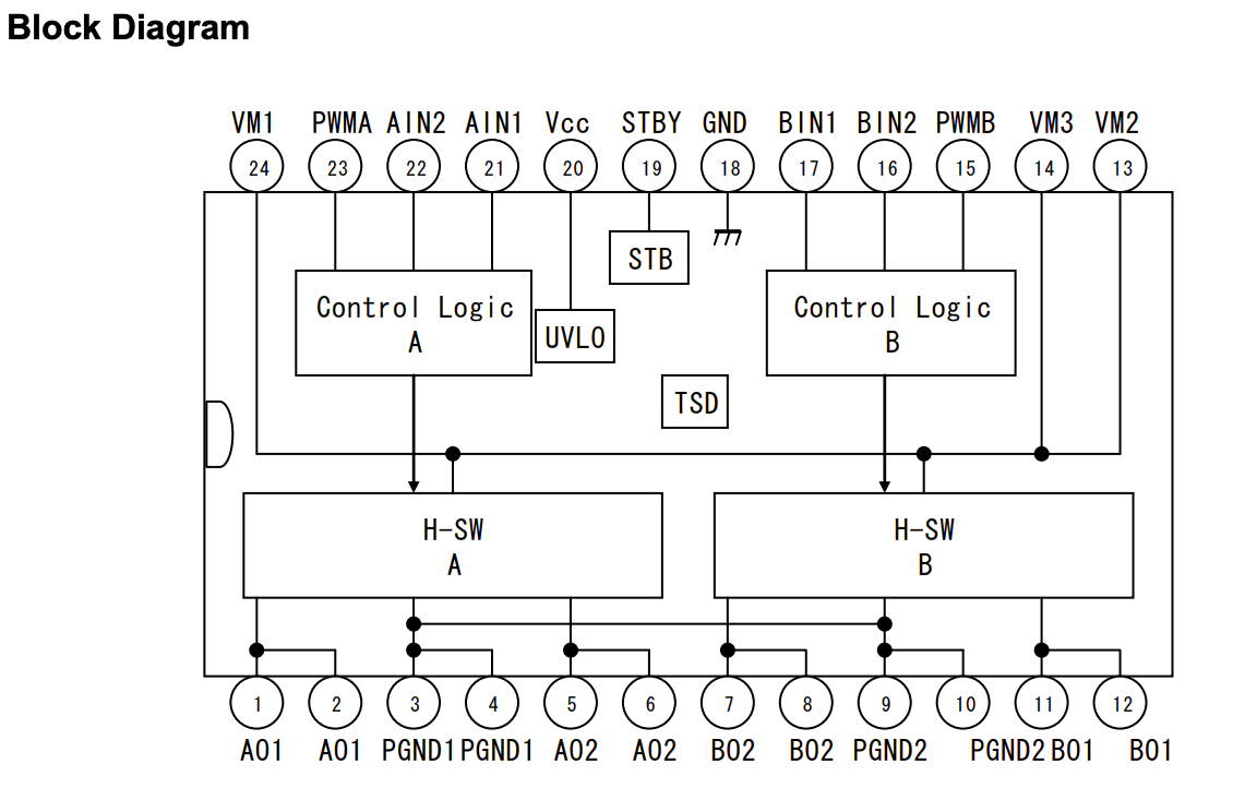
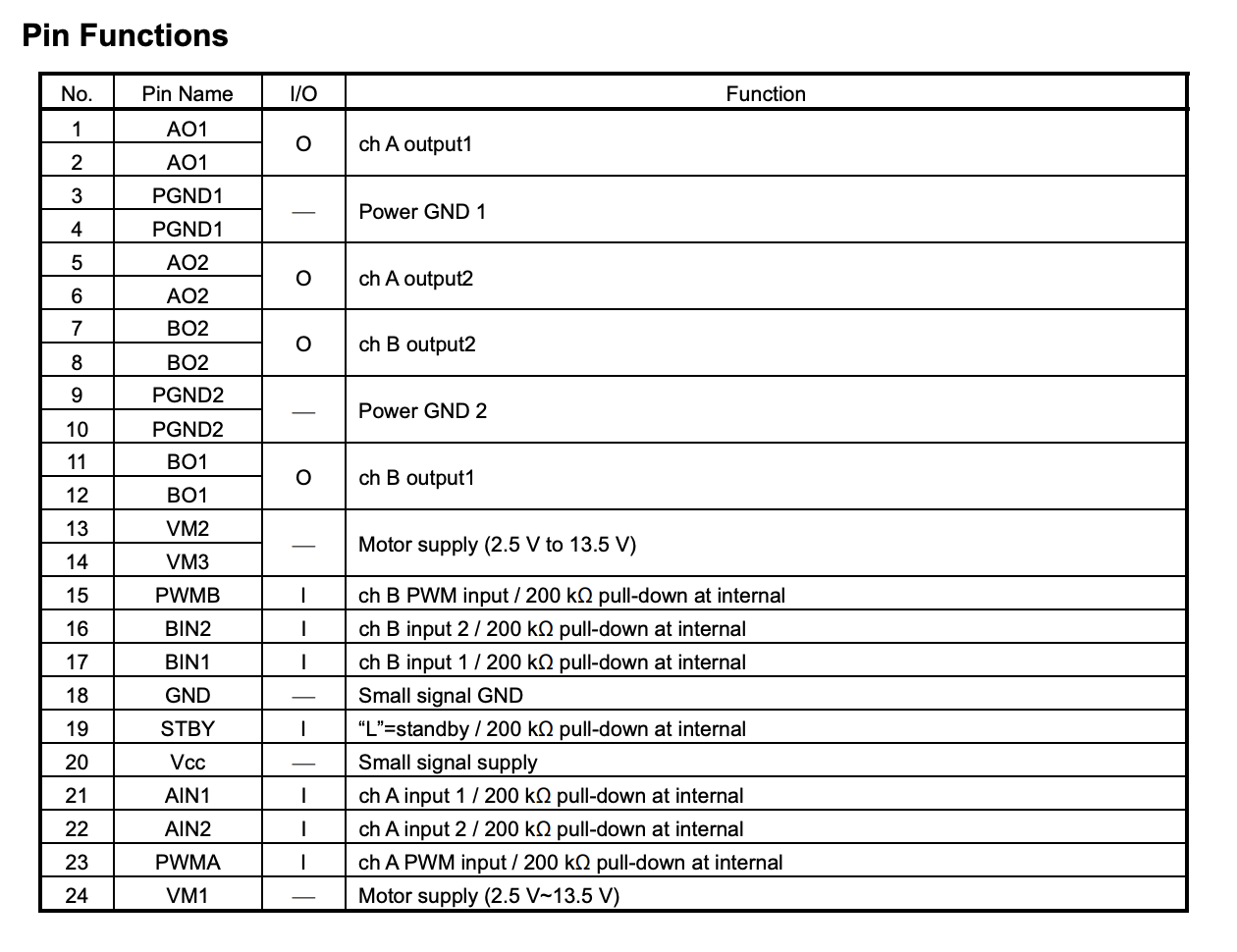
From the datasheet, I could find out
- The motor driver have two PWM input pins and each pins connect to each control Logic of the DC motor. That means, I could connect those pins to PWM pins of microcontrollers, and it would be enough two microcontroller pins for PWM (not four pins).
- Four Input pins in the motor driver, those pins send a digital HIGH/LOW for controlling the motors.
- Vcc: power supply pin for motor driver. Maximum would be 6V.
- VIM1~3: Motor supply from 2.5V - 13.5V
Then, I tried to check how does TB6612FNG works with satshakit. I have already made one satshakit board that is used in our MTM week assignment. Based on the experiences that controlled two stepper motors from satshakit in MTM week assignment (REFERENCE: Assignment week 15), I used breakout board version of TG6612FNG.
Before do that, I checked the datasheet of ATMega328p (microcontroller of satshakit). I could see the datasheet here.
Here is the pin configuration of ATmega328p
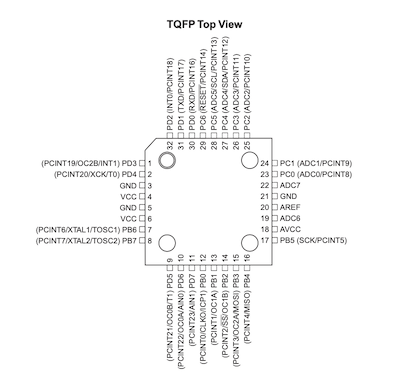
According to the datasheet, ATMega328p have six PWM mode channel, and those are OC2A,OC1A,OC0A,OC0B,OC2B,OC1B. I should connect two of those pins to TG6612FNG’s PWMA and PWMB.
(notice: I could find it later. First, I thought have to connect those PWM pins to TB6612FNG’s four input pins. It would makes PCB designing difficult. I will mention about it sometimes in below.)
Also checking satshakit designed board.

Because satshakit is an Arduino UNO compatible board, the following Pin Number regards as Arduino UNO pin number.
| ATMega328P Assigned Pins | Satshakit Pin Number |
|---|---|
| OC0A | D6 |
| OC0B | D5 |
| OC1A | D9 |
| 0C1B | D10 |
| 0C2A | D11 |
| 0C2B | D4 |
OK, now is the time for wiring each other (satshakit, motor drivers and DC motors). For checking, I used TB6612FNG module from Sparkfun The following chart is basic schema for wiring each other.
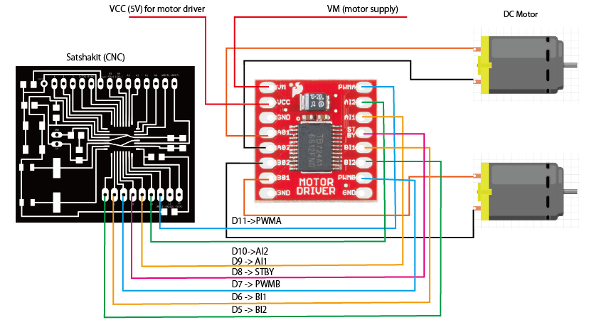
(Notice: I have found out this wiring plan makes very difficult to drawing on the EAGLE, and I change the pattern of wiring. I will notice it later.)
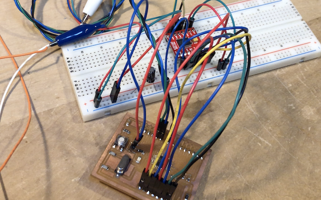
Then, wiring each parts.
Programming for controlling motor drivers and Testing
Now is to write a code for controlling wired motor driver. I just write a code to continue rotating and reversing 1 seconds in each side of legs with Arduino.
DCmotor_test.ino
#include <Wire.h>

const int motorA1 = 9;  // IN1
const int motorA2 = 10;  // IN2
const int motorAp = 11;  //
const int motorB1 = 6;  // IN1
const int motorB2 = 5;  // IN2
const int motorBp = 7;  //
const int STBY = 8;
void setup() {
  // put your setup code here, to run once:
  pinMode( motorA1, OUTPUT );
  pinMode( motorA2, OUTPUT );
  pinMode( motorAp, OUTPUT );
  pinMode( motorB1, OUTPUT );
  pinMode( motorB2, OUTPUT );
  pinMode( motorBp, OUTPUT );
  pinMode( STBY, OUTPUT );

  digitalWrite( motorA1, LOW );
  digitalWrite( motorA2, LOW );
  digitalWrite( motorAp, LOW );
  digitalWrite( motorB1, LOW );
  digitalWrite( motorB2, LOW );
  digitalWrite( motorBp, LOW );
  digitalWrite( STBY, HIGH );

  Serial.begin(9600);
  Serial.println( "Motor Standby" );
  delay( 1000 );
}

void loop() {
  // put your main code here, to run repeatedly:
  Serial.println("motorA forward");
  digitalWrite( motorAp, HIGH );
  digitalWrite( motorA1, HIGH );
  digitalWrite( motorA2, LOW );
  delay( 3000 );
  Serial.println("motorA stop");
  digitalWrite( motorAp, LOW );
  delay( 1000 );
  Serial.println("motorA back");
  digitalWrite( motorAp, HIGH );
  digitalWrite( motorA1, LOW );
  digitalWrite( motorA2, HIGH );
  delay( 3000 );
  Serial.println("motorA stop");
  digitalWrite( motorAp, LOW );
  delay( 1000 );

  Serial.println("motorB forward");
  digitalWrite( motorBp, HIGH );
  digitalWrite( motorB1, HIGH );
  digitalWrite( motorB2, LOW );
  delay( 3000 );
  Serial.println("motorB stop");
  digitalWrite( motorBp, LOW );
  delay( 1000 );
  Serial.println("motorB back");
  digitalWrite( motorBp, HIGH );
  digitalWrite( motorB1, LOW );
  digitalWrite( motorB2, HIGH );
  delay( 3000 );
  Serial.println("motorB stop");
  digitalWrite( motorBp, LOW );
  delay( 1000 );
}
Then, I checked whether the motor drivers works well and the 6 legs moves correctly.
Well done.
PCB Designing and Milling
Now, it is time to move to designing of my PCB with Autodesk EAGLE. I will make my own PCB with revising satshakit.
Designing with Autodesk EAGLE
There are a couple of things I have to considered. One is the position of TB6612FNG. I downloaded EAGLE file of satshakit, then I checked the board design file of that…
My plan of revising satshakit are:
- add TB6612FNG on the right bottom area. TB6612FNG input pins should be connected to ATMega 328’s No.9 ~ 16 pins (satshakit D5 ~ D11 digital pins).
- 5 voltage regulator. I want to connect 4 x AA battery pack and supply 6 voltage. As I learned from Output device week assignment, I will add 5V regulator near the power supply pin and change some pattern of wiring from output pin of the regulator to microcontroller.(REFERENCE: Week 12 Output Device Week assignment)
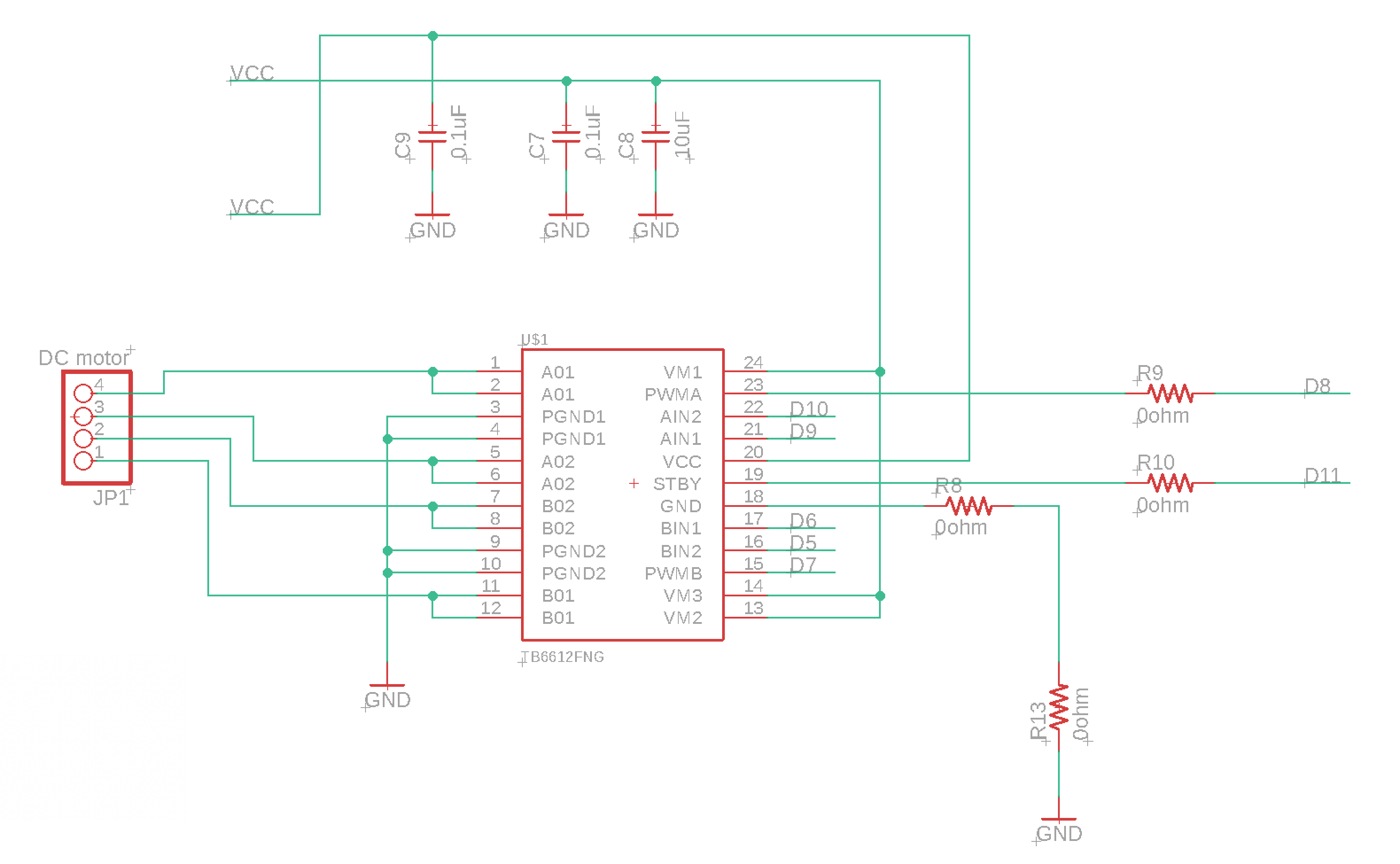
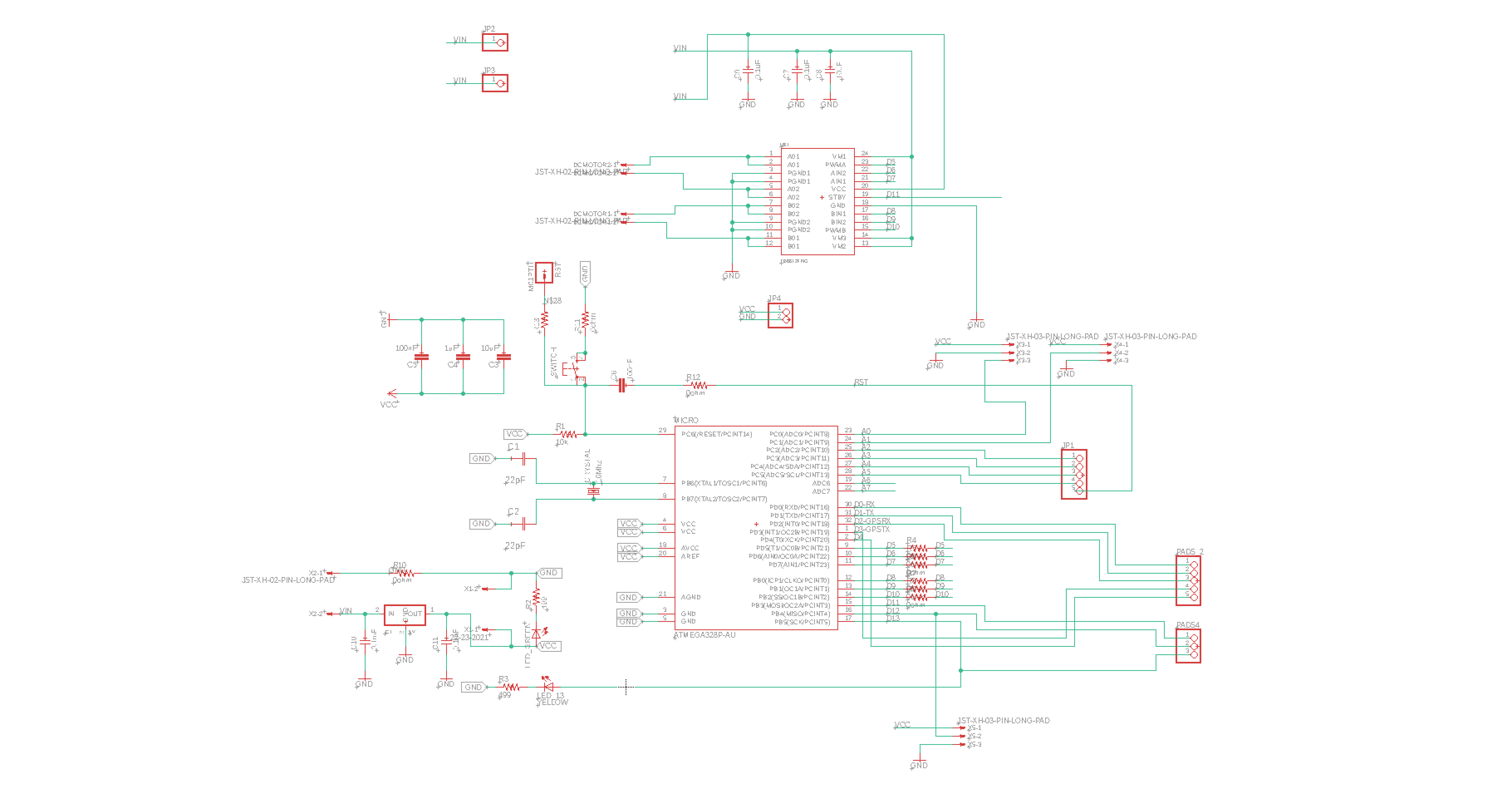
Then, I draw the schema as follow.
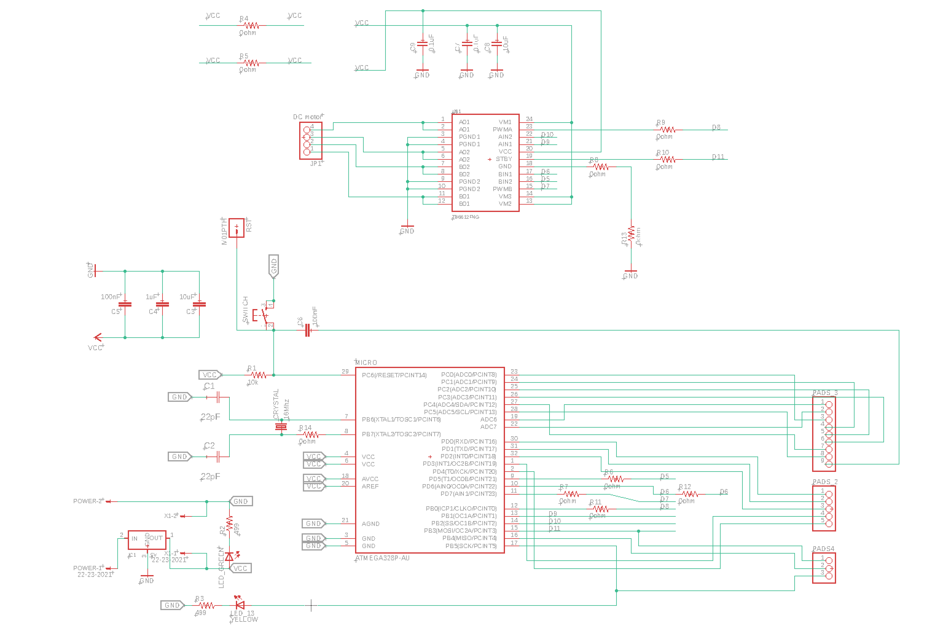
Here is the schema of TB6612FNG. According to the datasheet of TB6612FNG, it require to add 0.1uF and 10uF capaciters and those should be connect to VIM (power supply pin to the motor) and put near from the driver. Also, one 0.1uF capaciter should be connected to VCC of the motor driver.
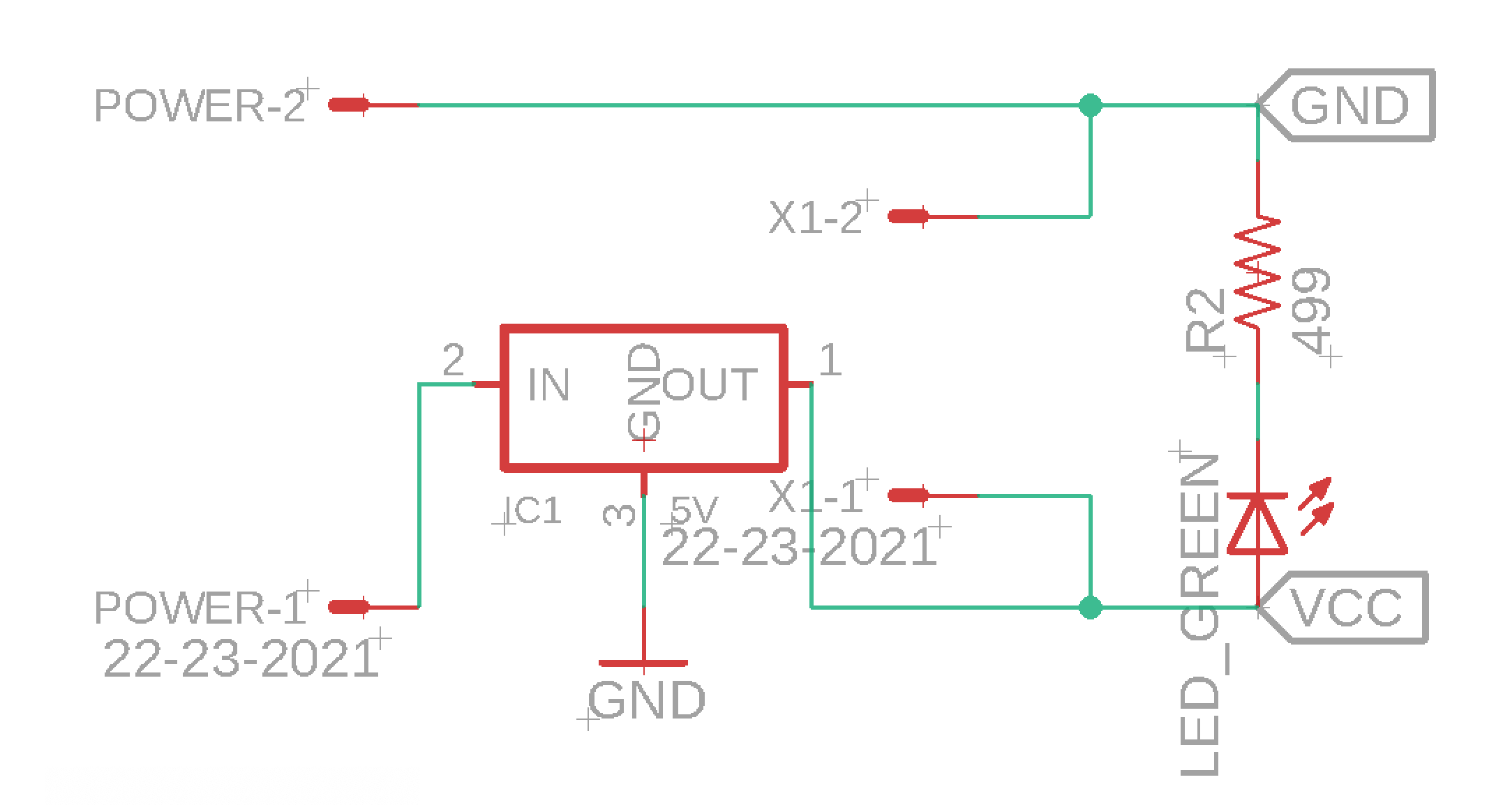
Also, here is the schema of power supply area. I added a regulator, whereas I also leave original VCC and GND pins. I could use those pins for power supply to some sensor modules or wifi.
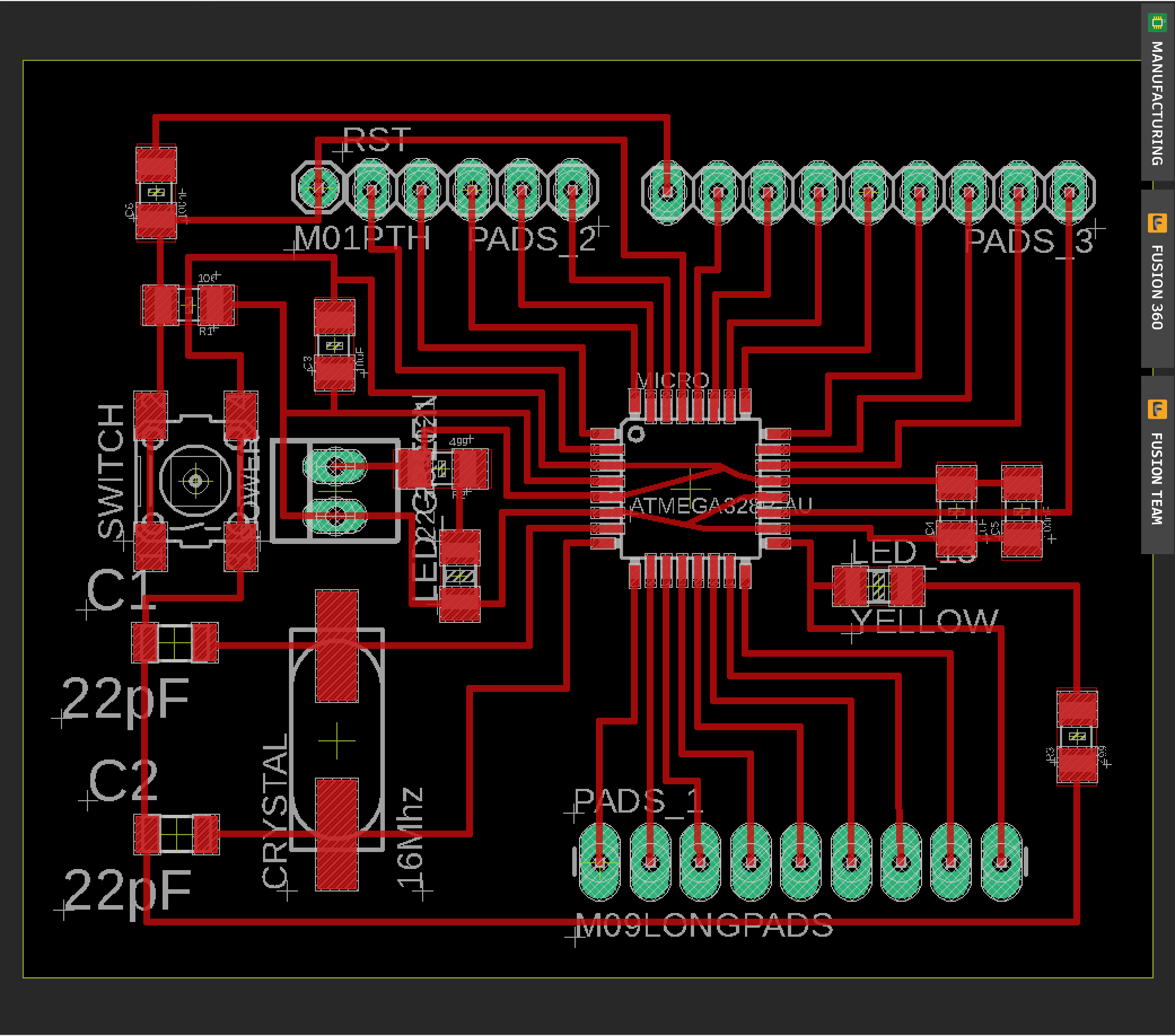
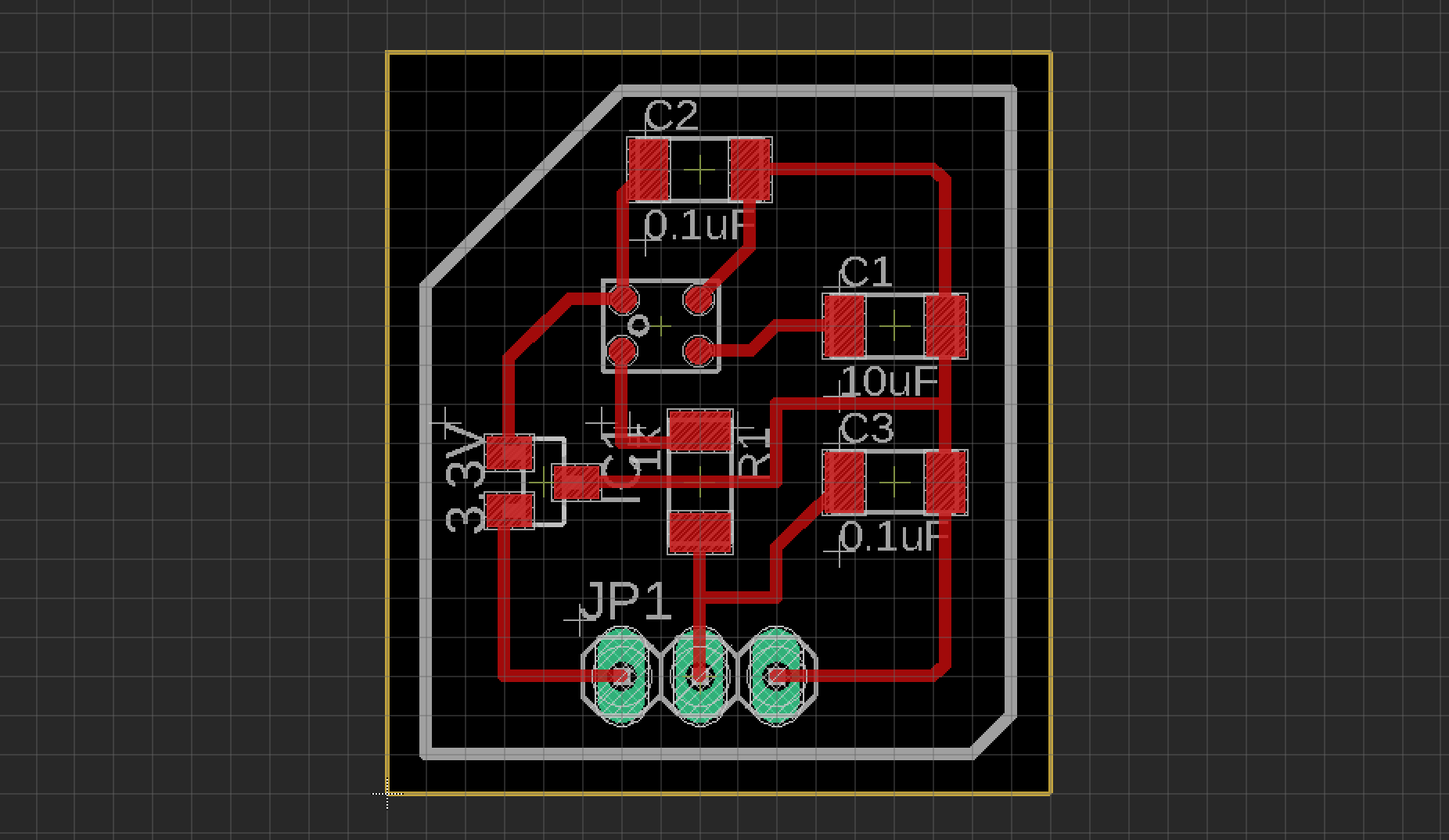
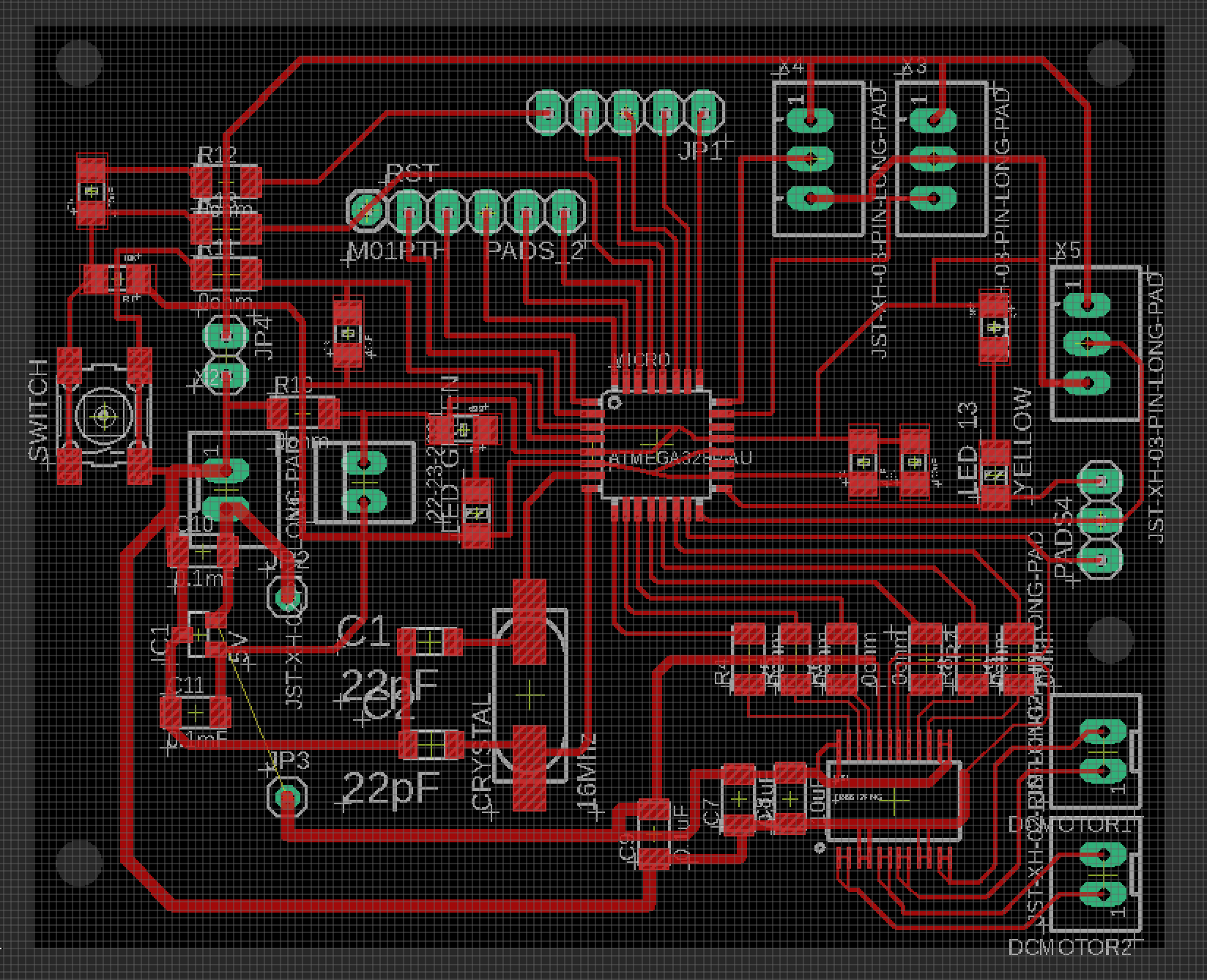
Then, I draw the board design as follow.
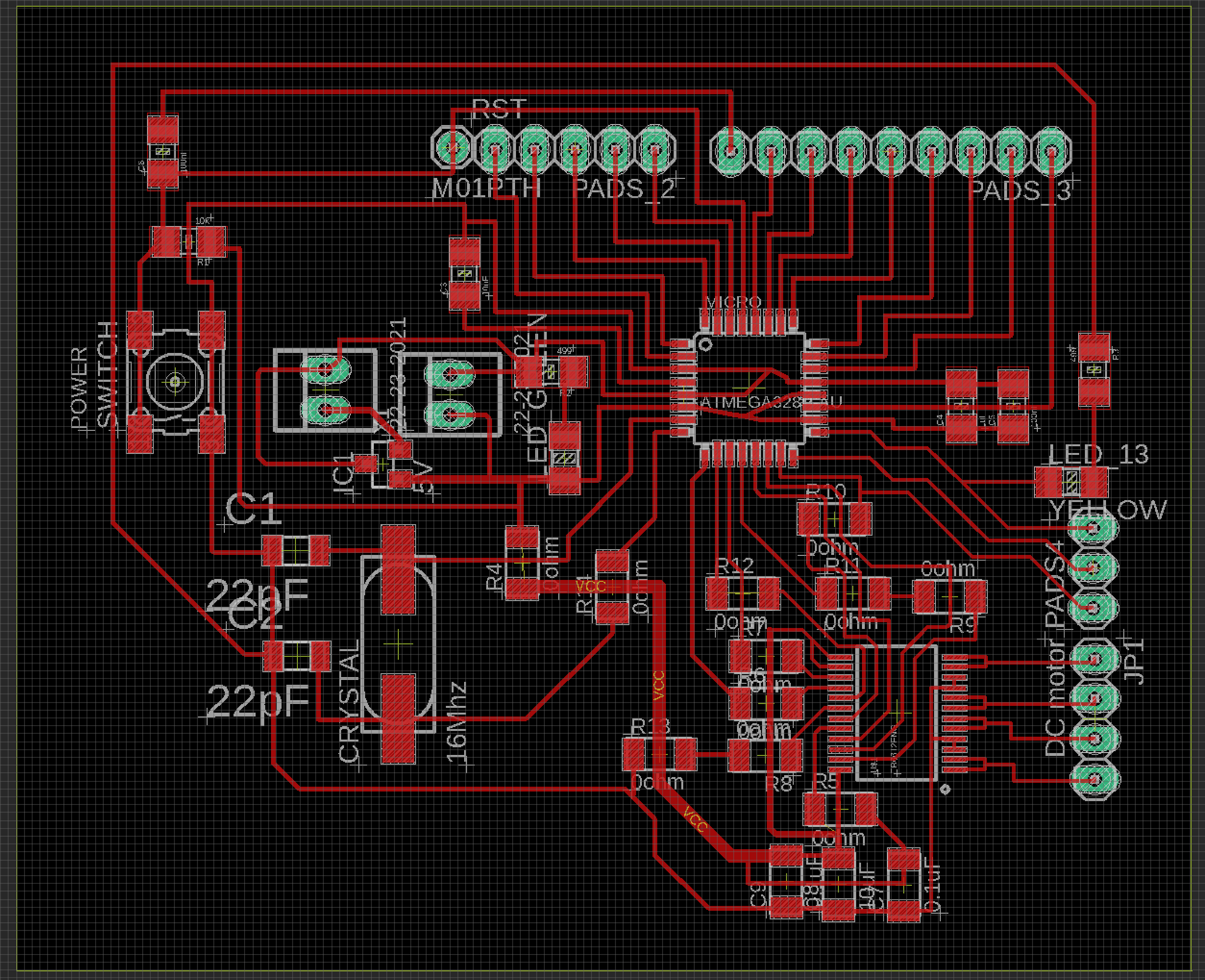
Also, here is the outline design of the board.

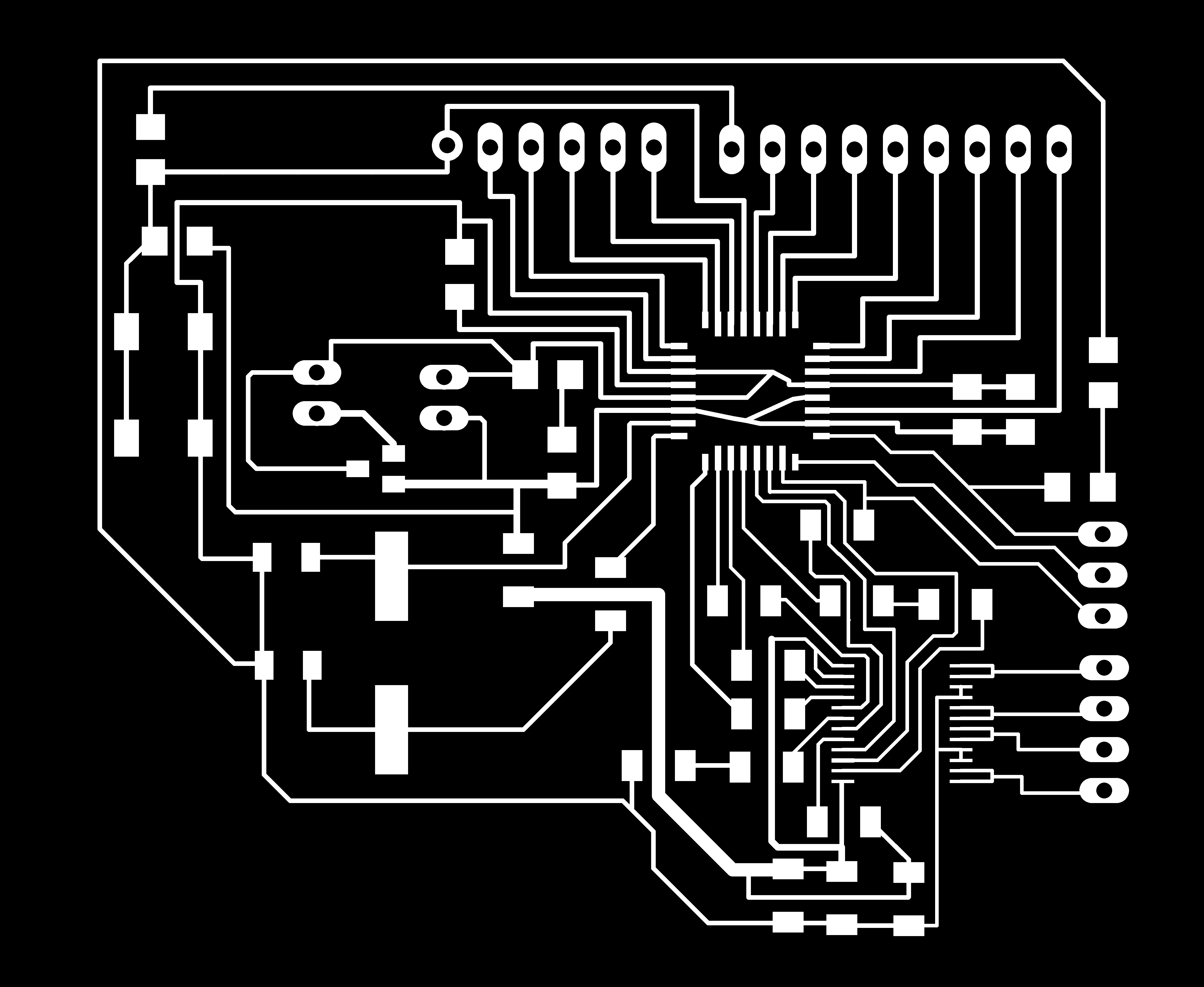
Then, making a PNG file of trace, hole and outline of the board.

Making CAM file and milling, soldering
Then, open the mods and make CAM files for milling.
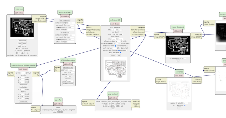
Also, checking whether pathes for milling are traced or not.
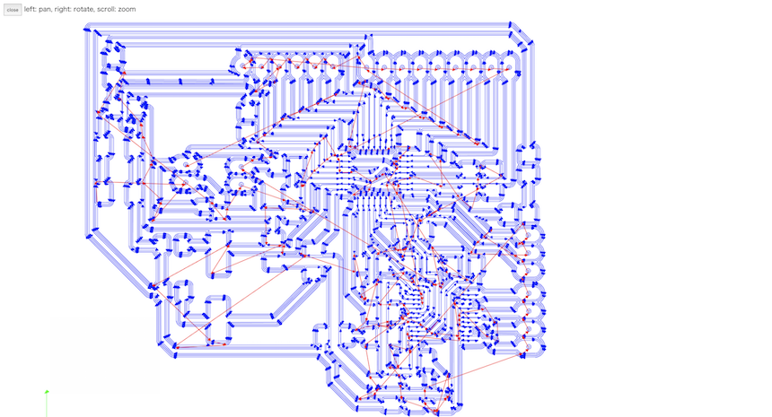
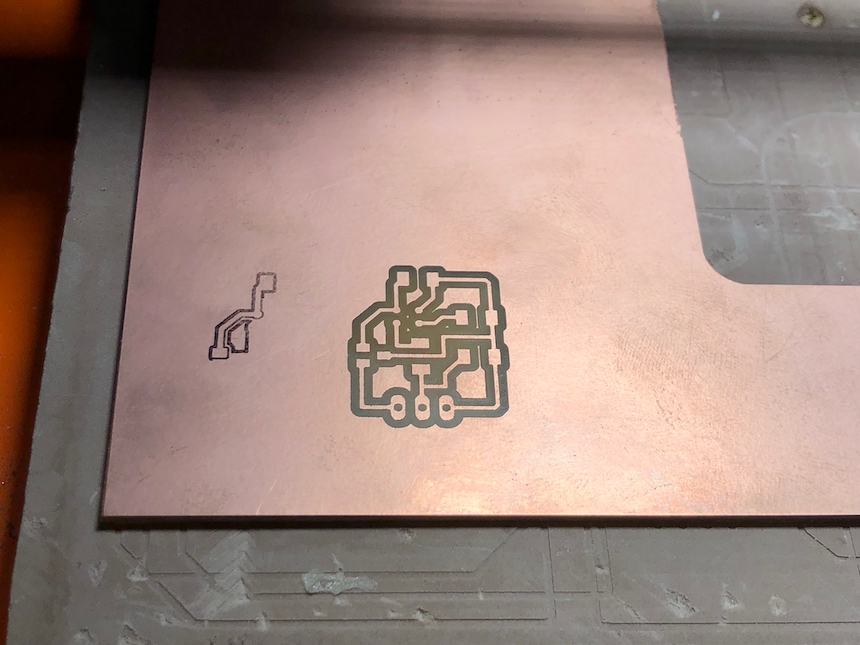
Now, it’s time for milling PCB.
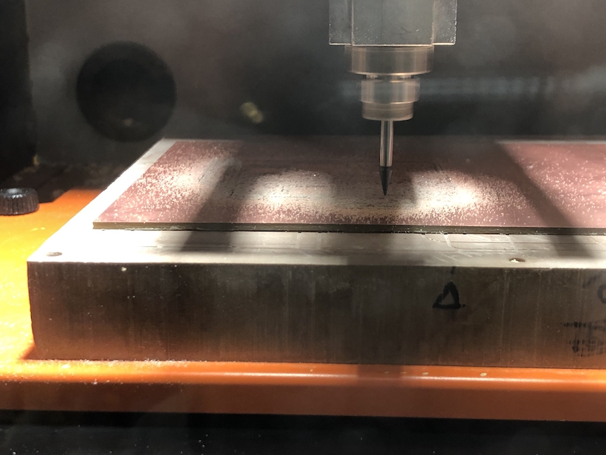
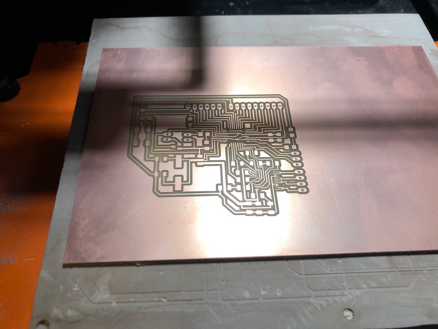
Milling and soldering
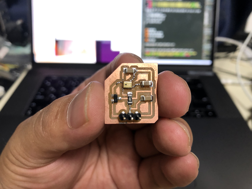
Completed the PCB (1st version).
Checking
Using the same code (DCmotor_test.ino), I checked whether it works or not.
Some motor driver pins had not soldered well, so I fixed them. Then, the motor worked well!!!
Input Device (Sensor) Module
Well, I move to make sensor (input) devices. I want to design my PCB to connect various kinds of sensors. Therefore, it is better not to equip them into PCB but to make (or use) modules of sensors that I want to add. Analog sensors should be included VCC, GND and ADC pins. Also, in case of digital sensor, it should be included VCC, GND and digital input pins. (Some digital sensors such as UltraSonic Sensors require VCC, GND, digital output and input).
I tried to make a sensor module and connect it to the PCB that I made. This time, I made a sound sensor module with reffering the sample in Input device week.
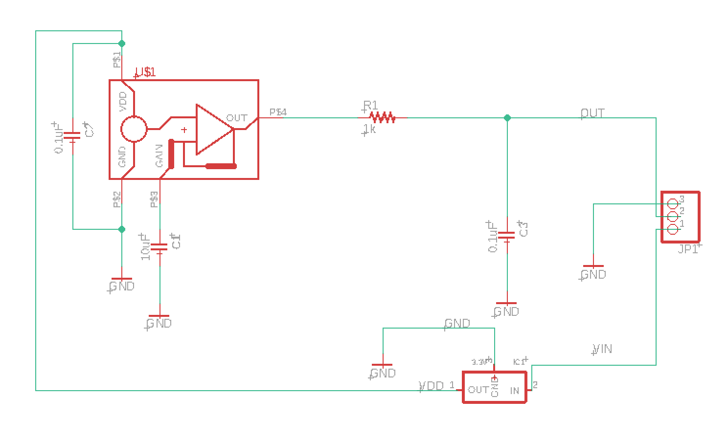
I choosed analog sound sensor SPU0414HR5H . The following is the sample circuit of this sound sensor.
From the sample board and the datasheet of SPU0414HR5H, basically I could arrange to design the schema and the board for making the module of this sensor. Because maximum voltage of the senser would be 3.6v, and I have to add 3.3v regulator near the VIN of sensor module.
Here is the schema in Autodesk EAGLE
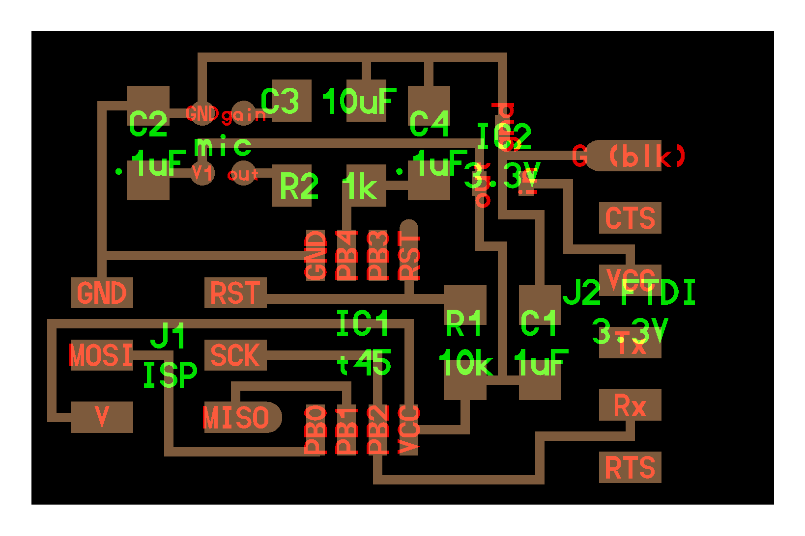
Then, designing the board as follow:
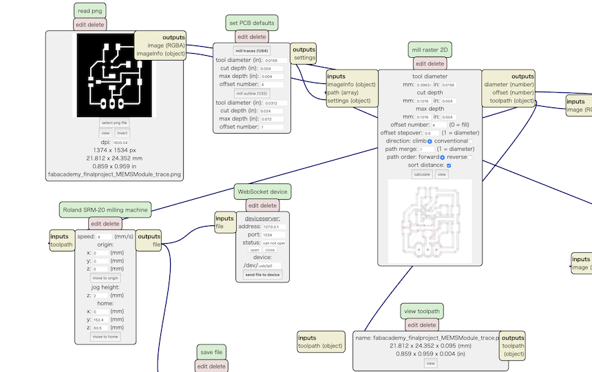
And, export to PNG images for making CAM file in mods.
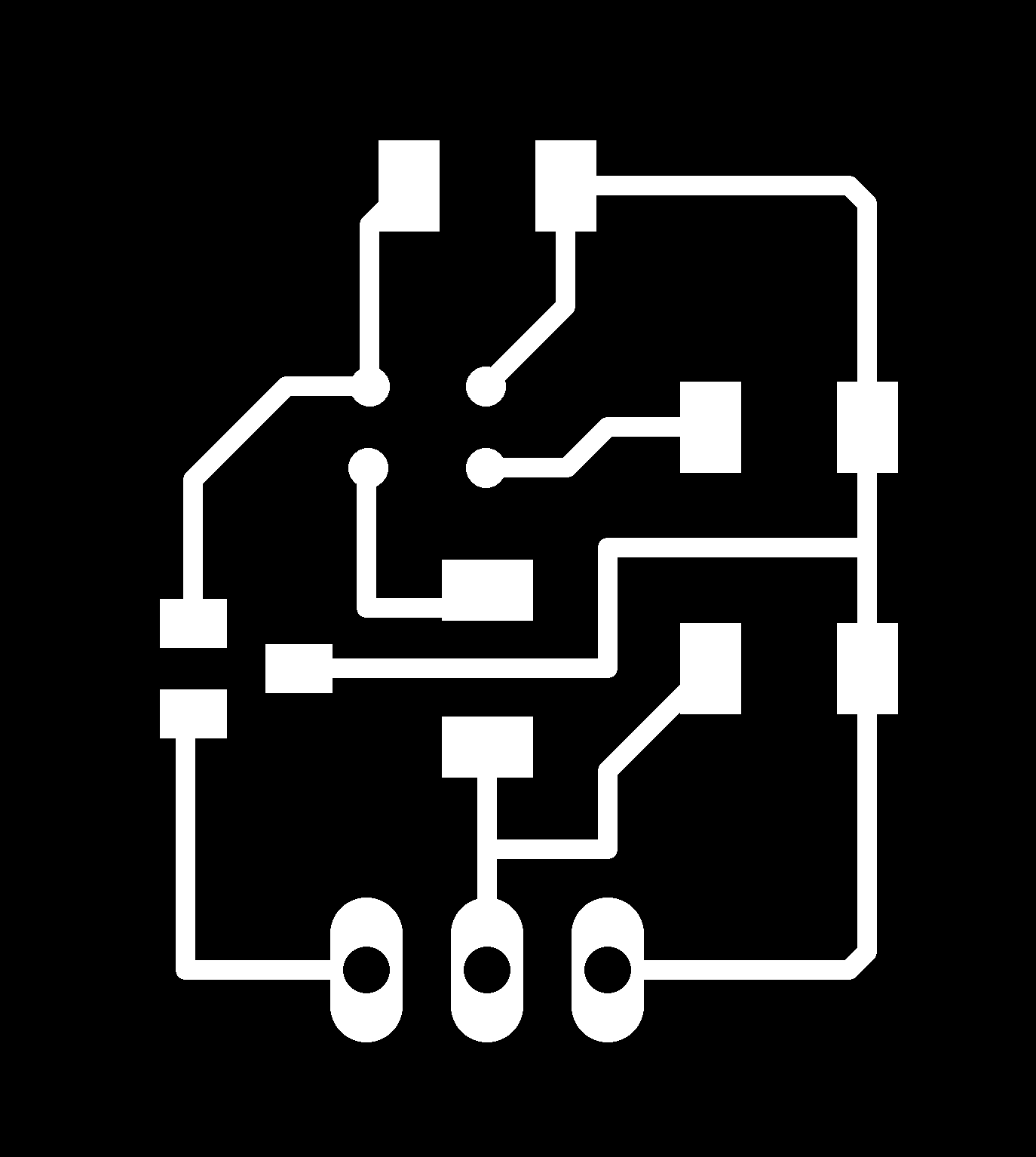


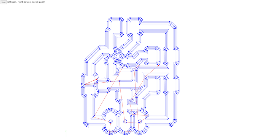
Making the CAM file for Roland SRM-20. Also checking whether the circuit is traced correctly.
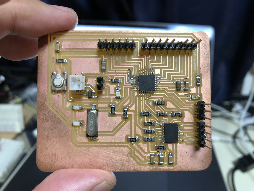
Then, milling and soldering
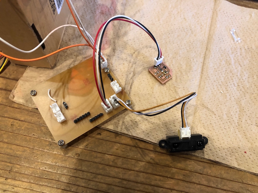
So, I connected this sensor module as follow
- VCC -> PCB’s VCC pin
- GND -> PCB’s GND pin
- ADC -> PCB’s A1 pin
Then, I wrote a code that just reading analog value from A1 pin.
MEMS_TEST.ino
void setup() {
  // put your setup code here, to run once:
  Serial.begin(9600);

}

void loop() {
  // put your main code here, to run repeatedly:
  //analogReference(INTERNAL);
  int val = analogRead(1);

  Serial.println(val);
  delay(100);

}
Then checked whether the microcontroller read the analog value from the sensor module.
The video shows…
- The graph on the PC display shows the analog value of A1 pins (that connect to MEMS sensor module)
- And the graph is changing by the stress of the sounds.
The MEMS sensor module works well. And, I could regard this approach (making sensor module by myself and add it to my PCB) would be a reasonable.
Assembling
At this point, I have completed
- Designig of 6 legs mechanical and make it with Computer-Controlled Cutting approach
- Making PCB with revising satshakit
- Making sensor module that connect to the PCB
- Designing Insect Body and make it with 3D printing approach
Then, I will move to assembling each parts. Before assembling each parts, I have to revise some design that I have already made.
Revising PCB design
The above PCB is something problems.
- Connectors: Everything connecting to PCB, such as DC motors, Sensor modules and so on. It should be revised to use XH Connectors.
- 5 voltage regulator. It should add 1uF capaciters to VIN and GND.
- Wiring TB6612FNG: As noticed before, I thought have to connect those PWM pins to TB6612FNG’s four input pins. It would makes PCB designing difficult.
- Separate VCC line for motor drive from VCC line for microcontroller
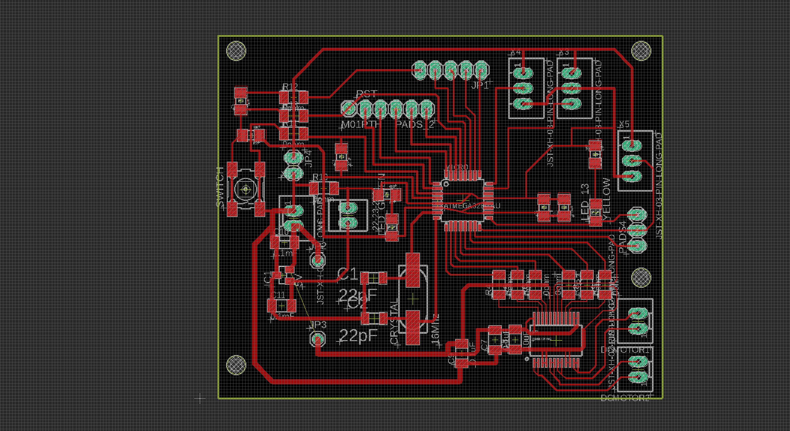
So, I revised the schema and board design of my PCB as follow. The revised schema is here:
Here is the board design of revised PCB
Revising Base board of Mecnanical parts and PCB
In order to fix PCB on the base board of mechanical parts, I have to revise outline of the PCB and add holes for connecting spacers. But, the position of the spacers and the size of the PCB should be designed on the Mechanical base.
So, I re-designed outline of PCB on the Autodesk Fusion and adjust it to the EAGLE files. First, I make a “PCB Board” on the base board of mechanical.
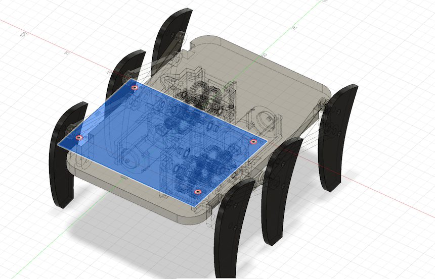
Next, open the PCB file in the EAGLE and import PCB outline design from Autodesk Fusion.
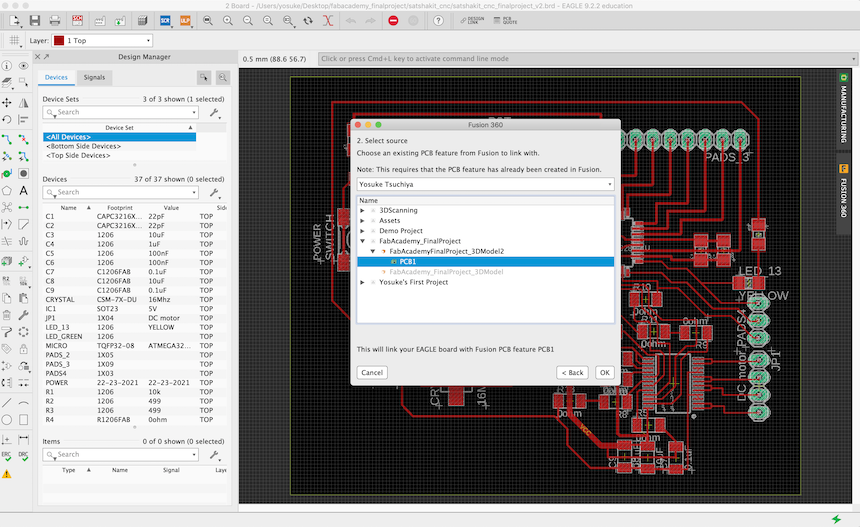
Then, I could see the outline file changed and the holes for spacer is added (Yellow line).
Also, make holes on Base Board of Mechanical part.
![]()
Milling and Cutting Re-designed ones.
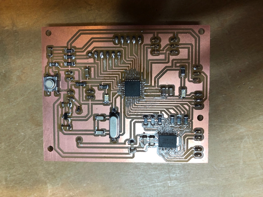
Milling and Soldering re-designed PCB.
Cutting re-designed Base Board of Mechanical part
Wiring and Assembling
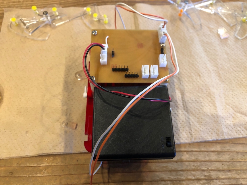
OK, now is the time to wiring and assembling each parts.
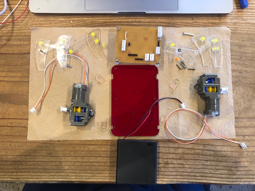
Assembled DC motors, PCB and 4 x AA battery pack.
Connecting Sensor module
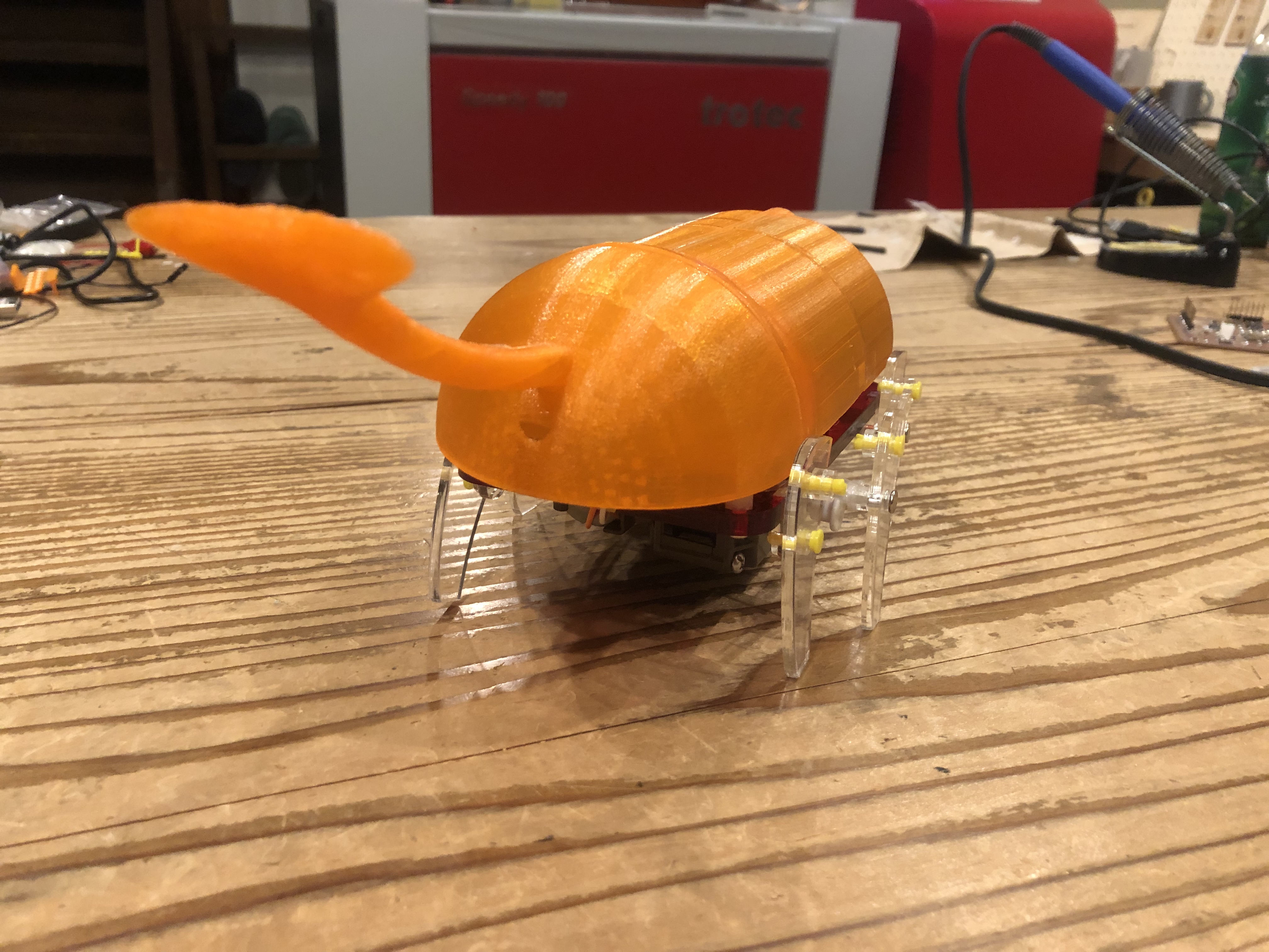
Then, add Insect body on the mechanical part.
Programming
I wrote a program that the robot walk and get the Sound sensor. Sound sensor data would transmit by serial bus.
Fabacademy_finalproject.ino
#include <Wire.h>

const int motorA1 = 8;  // IN1
const int motorA2 = 9;  // IN2
const int motorAp = 10;  //
const int motorB1 = 7;  // IN1
const int motorB2 = 6;  // IN2
const int motorBp = 5;  //
const int STBY = 11;


void setup() {
  // put your setup code here, to run once:
  pinMode( motorA1, OUTPUT );
  pinMode( motorA2, OUTPUT );
  //pinMode( motorAp, OUTPUT );
  pinMode( motorB1, OUTPUT );
  pinMode( motorB2, OUTPUT );
  //pinMode( motorBp, OUTPUT );
  pinMode( STBY, OUTPUT );

  digitalWrite( motorA1, LOW );
  digitalWrite( motorA2, LOW );
  digitalWrite( motorAp, LOW );
  digitalWrite( motorB1, LOW );
  digitalWrite( motorB2, LOW );
  digitalWrite( motorBp, LOW );
  digitalWrite( STBY, HIGH );

  Serial.begin(9600);
  delay( 1000 );
}

void loop() {
  // put your main code here, to run repeatedly:
  //Serial.println("motorA forward");

   analogWrite( motorAp, 100 );
   digitalWrite( motorA1, HIGH );
   digitalWrite( motorA2, LOW );
   delay( 100 );
   analogWrite( motorAp, 0 );
   delay( 100 );

   analogWrite( motorBp, 100 );
   digitalWrite( motorB1, HIGH );
   digitalWrite( motorB2, LOW );
   delay( 100 );
   analogWrite( motorBp, 0 );
   delay(100);

  // Reading MEMS data
  digitalWrite( motorA1, LOW );
  digitalWrite( motorA2, LOW );
  digitalWrite( motorAp, LOW );
  digitalWrite( motorB1, LOW );
  digitalWrite( motorB2, LOW );
  digitalWrite( motorBp, LOW );

  int MEMSval = analogRead(1);
  Serial.println(MEMSval);

}
Demonstrations
Finally, I have completed to assembling all parts I made.
So, first, checking whether it walks as robot or not.
Next, checking whether the input device module (MEMS sound sensor) works or not:
That works well !!!!
Revised (add logging function into EEPROM)
At this point, SENSING BEETLE have the functions that walk around and get the sensor data. However, the robot still could not record the sensor data.
To record the input data such as sound sensor, I added the function to record it into EEPROM of ATMega328p.
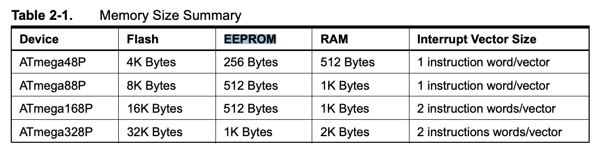
EEPROM(electrically erasable and programmable read only memory) is the memory that could be used for saving, erasing and writing some temporary data. According to the datasheet, ATMega328p have 1K byte EEPROM located.
To record the sensor data into EEPROM, first, I revised the Arduino code for walking robot. The code read the sensor data and record it while the robot walking around.
#include <Wire.h>
#include <EEPROM.h>

const int motorA1 = 8;  // IN1
const int motorA2 = 9;  // IN2
const int motorAp = 10;  //
const int motorB1 = 7;  // IN1
const int motorB2 = 6;  // IN2
const int motorBp = 5;  //
const int STBY = 11;


int addr = 0;
byte values;

void setup() {
  // put your setup code here, to run once:
  pinMode( motorA1, OUTPUT );
  pinMode( motorA2, OUTPUT );
  pinMode( motorAp, OUTPUT );
  pinMode( motorB1, OUTPUT );
  pinMode( motorB2, OUTPUT );
  pinMode( motorBp, OUTPUT );
  pinMode( STBY, OUTPUT );

  digitalWrite( motorA1, LOW );
  digitalWrite( motorA2, LOW );
  digitalWrite( motorAp, LOW );
  digitalWrite( motorB1, LOW );
  digitalWrite( motorB2, LOW );
  digitalWrite( motorBp, LOW );
  digitalWrite( STBY, HIGH );

  Serial.begin(9600);
  delay( 1000 );
}

void loop() {
  // put your main code here, to run repeatedly:
  //Serial.println("motorA forward");


     analogWrite( motorAp, 100 );
     digitalWrite( motorA1, HIGH );
     digitalWrite( motorA2, LOW );
     delay( 200 );
     writeMEMS();

     analogWrite( motorAp, 0 );
     delay( 200 );
     writeMEMS();

     analogWrite( motorBp, 120 );
     digitalWrite( motorB1, HIGH );
     digitalWrite( motorB2, LOW );
     delay( 200 );
     writeMEMS();

     analogWrite( motorBp, 0 );
     delay(200);
     writeMEMS();

    digitalWrite( motorA1, LOW );
    digitalWrite( motorA2, LOW );
    digitalWrite( motorAp, LOW );
    digitalWrite( motorB1, LOW );
    digitalWrite( motorB2, LOW );
    digitalWrite( motorBp, LOW );

}


void writeMEMS(){
 int MEMSval = analogRead(1);
  int valtoEEPROM = MEMSval / 4;
  EEPROM.write(addr,valtoEEPROM);

  addr = addr + 1;
  if(addr == EEPROM.length()){
    addr = 0;
  }

}
Then, after finishing to walking aroud and getting sensor data, I uploaded the following code to read the data in EEPROM and transfer it to Serial tx line.
#include <EEPROM.h>

int address = 0;
byte value;

void setup() {
  // put your setup code here, to run once:
  Serial.begin(9600);
  while(!Serial){
    ;
  }

}

void loop() {
  // put your main code here, to run repeatedly:
  value = EEPROM.read(address);
  Serial.println(value,DEC);


  address = address + 1;
  if(address == EEPROM.length()){
    address = 0;
  }
  delay(500);
}
Afterthat, I wrote the simple program to read Serial rx and save those data into the .log file in my Macbook Pro.
import processing.serial.*;

Serial myPort;
String dataStr;
PrintWriter output;

int count = 1;

int x;
int values[] = new int[300];

Date tmpTime = new Date("2019/06/24 10:10:03");

String showvalues;

void setup(){

  size(800,600);
  frameRate(30);


  println(Serial.list());
  myPort = new Serial(this, Serial.list()[3],9600);
  //myPort.clear();
 output = createWriter("sensordata.csv");
 pixelDensity(displayDensity());


}

void draw(){


}

void serialEvent(Serial p){

    if (p.available() > 0) {
    try {
      String input = p.readStringUntil('\n');
      if (input != null) {

         output.print(input);
         print(input);

       }
    } catch (RuntimeException e) {
    }
  }

}

void keyPressed() {
  if(key == 'a'){
    output.flush();
    output.close();
    exit();
  }

  if(key == 'r'){
    myPort.write("r");
  }
}
THen, I tested those programs. The following video shows the recorded sensor data into EEPROM could read and save into my Computer.
I could record the sensor data into the EEPROM of the robot. But, it is still hard to use. So, I revised the program as following.
I revised the Arduino to integrate the function to sensing around and the function to read the data from EEPROM, and revised it to swtich the mode by sending some simple command via the Serial.
#include <Wire.h>
#include <EEPROM.h>

const int motorA1 = 8;  // IN1
const int motorA2 = 9;  // IN2
const int motorAp = 10;  //
const int motorB1 = 7;  // IN1
const int motorB2 = 6;  // IN2
const int motorBp = 5;  //
const int STBY = 11;


int addr = 0;
int readaddr = 0;
byte values;

String mode = "m";

void setup() {
  // put your setup code here, to run once:
  pinMode( motorA1, OUTPUT );
  pinMode( motorA2, OUTPUT );
  pinMode( motorAp, OUTPUT );
  pinMode( motorB1, OUTPUT );
  pinMode( motorB2, OUTPUT );
  pinMode( motorBp, OUTPUT );
  pinMode( STBY, OUTPUT );

  digitalWrite( motorA1, LOW );
  digitalWrite( motorA2, LOW );
  digitalWrite( motorAp, LOW );
  digitalWrite( motorB1, LOW );
  digitalWrite( motorB2, LOW );
  digitalWrite( motorBp, LOW );
  digitalWrite( STBY, HIGH );

  Serial.begin(9600);
  delay( 1000 );
}

void loop() {
  // put your main code here, to run repeatedly:
  //Serial.println("motorA forward");

  if(Serial.available() > -1){
    switch(Serial.read()){

      case 'm':
        mode = "m";
        break;
      case 'r':
        mode = "r";
        break;
    }
  }

  if(mode == "m"){
     analogWrite( motorAp, 100 );
     digitalWrite( motorA1, HIGH );
     digitalWrite( motorA2, LOW );
     delay( 200 );
     writeMEMS();

     analogWrite( motorAp, 0 );
     delay( 200 );
     writeMEMS();

     analogWrite( motorBp, 120 );
     digitalWrite( motorB1, HIGH );
     digitalWrite( motorB2, LOW );
     delay( 200 );
     writeMEMS();

     analogWrite( motorBp, 0 );
     delay(200);
     writeMEMS();

    digitalWrite( motorA1, LOW );
    digitalWrite( motorA2, LOW );
    digitalWrite( motorAp, LOW );
    digitalWrite( motorB1, LOW );
    digitalWrite( motorB2, LOW );
    digitalWrite( motorBp, LOW );

  }else if(mode == "r"){

    values = EEPROM.read(readaddr);
    Serial.println(values,DEC);

    readaddr = readaddr + 1;
    if(readaddr == EEPROM.length()){
      addr = 0;
    }

    delay(500);


  }


}


void writeMEMS(){
 int MEMSval = analogRead(1);
  int valtoEEPROM = MEMSval / 4;
  EEPROM.write(addr,valtoEEPROM);

  addr = addr + 1;
  if(addr == EEPROM.length()){
    addr = 0;
  }

}
Also, I revised the processing program to add the function to send the Serial command and start the mmode to read the sensor data from EEPROM. Also, I added to save appropriate date and time at the same time with sensor data into the .csv file.
import processing.serial.*;
import java.text.SimpleDateFormat;
import java.util.Date;
import java.time.LocalDateTime;
import java.util.Calendar;

Serial myPort;
String dataStr;
PrintWriter output;

int count = 1;

int x;
int values[] = new int[300];

Date tmpTime = new Date("2019/06/24 10:10:03");

String showvalues;

void setup(){

  size(800,600);
  frameRate(30);


  println(Serial.list());
  myPort = new Serial(this, Serial.list()[3],9600);

 output = createWriter("sensordata.csv");
 pixelDensity(displayDensity());


}

void draw(){

 background(color(30,30,30));
 stroke(255,255,255);
 textSize(16);
 text("Press 'r' key: to start serial communicatio  for getting sensor data from the robot.",20,20);
 text("Press 'a' key: to save sensor data into .csv file",20,40);

}

void serialEvent(Serial p){

    if (p.available() > 0) {
    try {
      String input = p.readStringUntil('\n');
      if (input != null) {

        String sdFormat = new SimpleDateFormat("yyyy/MM/dd hh:mm:ss").format(tmpTime);

        String insert = sdFormat + "," + input;

         output.print(insert);
         print(insert);
         String tmp = trim(input);

         append(values,int(tmp));
         Calendar calendar = Calendar.getInstance();
         calendar.setTime(tmpTime);
         calendar.add(Calendar.SECOND,1);
         tmpTime = calendar.getTime();

       }
    } catch (RuntimeException e) {
    }
  }

}

void keyPressed() {
  if(key == 'a'){
    output.flush();
    output.close();
    exit();
  }

  if(key == 'r'){
    myPort.write("r");
  }
}
Then, testing the code.... The folliwing video shows the function to swith the mode to read EEPROM data and save it into the .csv file.
And, I could save the sensor data with date and time into a csv file as following.
019/06/24 10:10:03,120
2019/06/24 10:10:04,125
2019/06/24 10:10:05,123
2019/06/24 10:10:06,127
2019/06/24 10:10:07,111
2019/06/24 10:10:08,117
2019/06/24 10:10:09,133
2019/06/24 10:10:10,131
2019/06/24 10:10:11,123
2019/06/24 10:10:12,124
2019/06/24 10:10:13,129
2019/06/24 10:10:14,130

...
Remained Task and Future Plan
Finally, I could make a robot that have minimum function for sensing. Basically, I was satisfied the result of my final project. However, I couldn’t implemented some functions by using Wireless Communications.
As a future plan, I will add Wi-Fi module to communicate with note PC or smartphone. Then, the following functions would be implemented.
- To record sensor data and transmit it to PC or Smaprtphone for visualizing and recording.
- To control the robot from PC or smartphone.
Also, if I could add the IR distance sensor, I could revise the robot for walking automatically by detecting obstactls and avoide them.