17. Machine design
The topic of this week is about Machine Design. We learn machine machine control, motion control, user interface for controling the machine and so on. This class and week 15 (Mechanical Design), those are important part for “Machin that make”, to make machine that make anything. The class video is here.
Assignment
group assignment
- actuate and automate your machine
- document the group project and your individual contribution
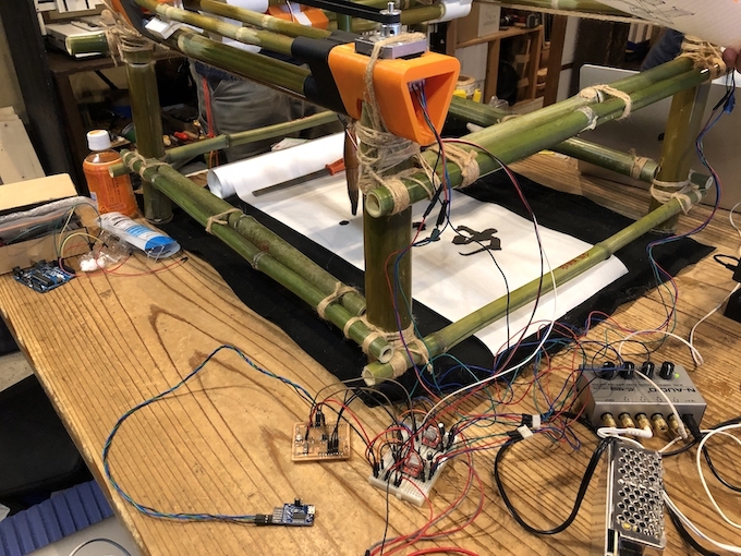
The assignment is a continuance of week 15 assignment. In these weeks, we make a machine that do something. We, students in Fab Lab Kamakura, build a Brush Painting Machine (BPM) to paint the two characters of the new era. And, we decided to use Japanese Bamboo for frames of the machine.
Our Group assignment page describe whole process of machine building. Please also see this week’s our group assignment page.
Our Machine: Brush Paint Machine
Please also see our machine: Brush Paint Machine.
Individual Contribution
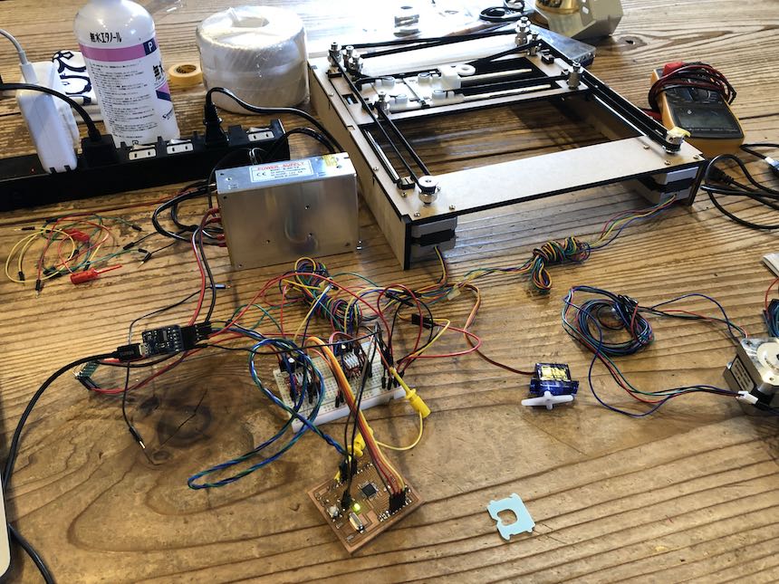
My task for machine building is about Electronics and Programming. Last week, I checked the mechanism of Core XY and design of the circuit to works Core XY Plotter. With using the Satshakit, an Arduino UNO compatible board, I confirmed whether the machine definitly works.
So, this week, I continued my study about Core XY and learned about G-Code for getting konw how to generate the data of characters that we want let machine write. First, I read the Core XY program based on Arduino and find out what functions are included. Then, I studied about G-Code, how to generate G-Code data and simulate it. Moreover, I studied how to develop interface application for sending G-Code data to the machine.
See also my assignment page for Week 15: Mechanical Design.
Core XY functions.
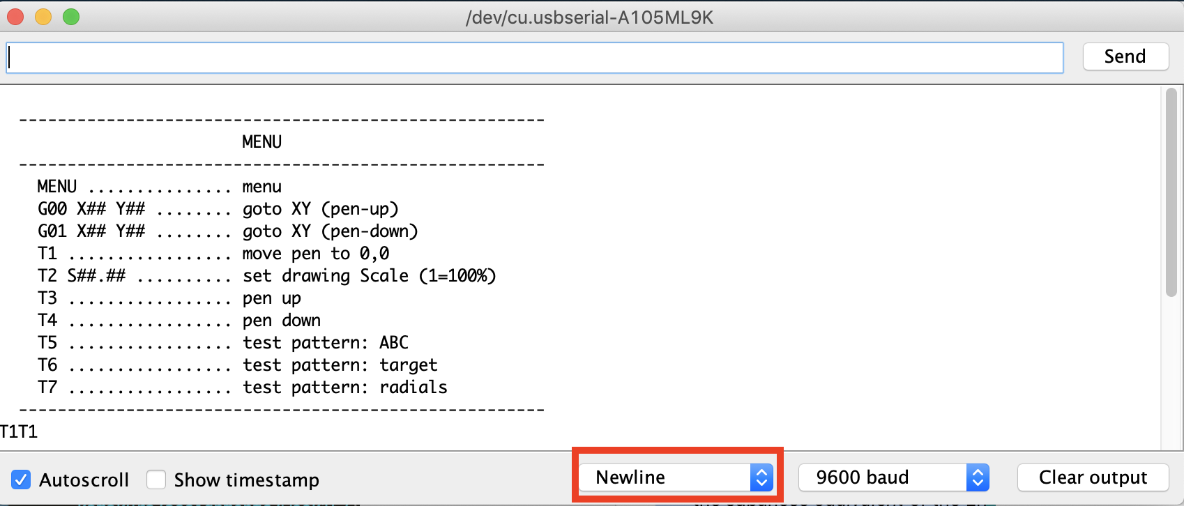
Opening serial monitor of Arduino (connecting to Satshakit that Core XY program is installed), we could find the following menu.
    MENU ............... menu
    G00 X## Y## ........ goto XY (pen-up)
    G01 X## Y## ........ goto XY (pen-down)
    T1 ................. move pen to 0,0
    T2 S##.## .......... set drawing Scale (1=100%)
    T3 ................. pen up
    T4 ................. pen down
    T5 ................. test pattern: ABC
    T6 ................. test pattern: target
    T7 ................. test pattern: radials
Basically, we send these command to control Core XY machine, and each functions that corresponded to each commands are defined in the Arduino program. In the main loop, the following code detecting which command are sended via serial port.
  // ----- get the next instruction
  while (Serial.available()) {
    INPUT_CHAR = (char)Serial.read();         //read character
    Serial.write(INPUT_CHAR);                 //echo character to the screen
    BUFFER[INDEX++] = INPUT_CHAR;             //add char to buffer
    if (INPUT_CHAR == '\n') {                 //check for line feed
      Serial.flush();                         //clear TX buffer
      Serial.write(XOFF);                     //pause transmission
      INPUT_STRING = BUFFER;                  //convert to string
      process(INPUT_STRING);                  //interpret string and perform task
      memset(BUFFER, '\0', sizeof(BUFFER));   //fill buffer with string terminators
      INDEX = 0;                              //point to buffer start
      INPUT_STRING = "";                      //empty string
      Serial.flush();                         //clear TX buffer
      Serial.write(XON);                      //resume transmission
    }
  }
Here, we have to take care that the end of serial character are detected new line ‘\n’. In Arduino serial monitor, we have to set “new line” located on the right bottom section. Also, when sending serial command from other program, we have to add ‘\n’ new line code. Otherwise, the program cannot detect the end of serial character and they cannot find out which command are received.
Then, I checked each command is what for.
T1: Calibrating XY origins manually
T1 command provides to move end-effector point to point. If we send T1 command, the program show the following submenu.
 ----------------------------------------------
    Position the pen over the 0,0 co-ordinate:
 ----------------------------------------------
    X-axis:             Y-axis:
   'A'  'S'            'K'  'L'
   <-    ->            <-    ->
    Exit = 'E'
With using these keys, we can move end-effector to the origin. We have to do this step when we turn on the machine.
T2: Drawing Scale.
This command determine which scale the end-effector moves. If we set 100%, the end effector moves in the same size with the data (For example, if we generate the G-code from Inkscape, the size of the drawing is the same with the one which is defined in Inkscape).
T3 and T4: Pen up and Pen down
This command control the servo motor, that lift up/down the pen connected to the end-effector. If we send T3 command, the servo motor rotate for pen up. If we send T4 command, the servo motor rotate for pen down. If we send T3 command and the pen is up, the servo motor doesn’t work.
T5 ~ T7: Run test pattern.
T5 ~ T7 commands run test patter for drawing. It is useful to check the machine works well. Those are recorded in the Arduino program, and we can learn how does the program interpret G-code to the position that the end effector moves by checking “process” function.
Studing G-Code and its application in Core XY
We need to generate G-code that Core XY machine draws. What is G-Code? According to the Autodesk page:
G-code is a programming language for CNC that instructs machines where and how to move. Most machines speak a different “dialect” of g-code, so the codes vary depending on type, make, and model. Each machine comes with an instruction manual that shows that particular machine’s code for a specific function.
Seeing inside of G-Code, it is a plain text file and each line consisits of command sets and position data like the following:
G02 X50.752716 Y22.976260 I-3.135884 J-1.324038
I learned the basic grammar of G-Code from the webpage at Make:. I will summarize some of basic G-Code grammars.
G0: Rapid Motion

The G0 command moves the machine at maximum speed to the position that is defined after the G0 command. For example, the code “G0 X7 Y18” means “move to X=7 and Y=18 position with maximum speed”. The important points (according to Makezine’s page) is that
- G0 is NOT used for cutting.
- it is used to move the machine quickly to begin a job or move to another operation within the same job.
G1: Controlled motion

G1 command is similar to G0 (move to specific XY position), but this command tell the machine to move at a user defined speed called feed rate(F)
G2: Clockwise motion

G2 command creates clockwise motion between the starting point and the specified ending points. The start point of the clockwise motion is defined by the offset from the center point.

The G2 starting point is where the machine is located prior to issuing the G2 Command (the end point of previous command result). It is better to move the machine to the starting point before trying to issue the G2 Command.
G3: Counterclockwise Motion

G3 command also creates an arc between two points. But, G3 command specifies counterclockwise motion (reverse direction) between the points.
G-Code in Core XY
In the Core XY, G-Code command would be work as following (according to the description in Core XY Arduino program).
- G0: liniar move with pen_up
- G1: liniar move with pen_down
- G2: clockwise arc with pen_down
- G3: counterclockwise arc with pen_down
In the Core XY machine, G0 (fast move) is used for moving the pen without drawing. Only G0 command do pen-up action, other commands (G1,G2,G3) do pen-down action. If we control the speed of pen-up/down action, we write some additional function here.
As, Kae Nagano (my class mate at Fab Lab Kamakura) mentioned in her works in MTM, we use ‘Fude’, brush of Japanese calligraphy as an end effector. And, one of the important technique is to sweep and life the brush gradually. “Sweep and lift” motion is something about the action in pen-up. So, I could find out if I add some code to G0 command section, the end effector works as our intentions (more intelligence).
Generating G-Code of Characters - How to.
Using Inkscape
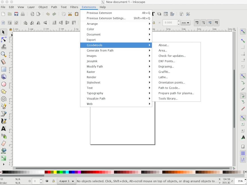
Generating G-Code itself is easy task. We can use Inkscape with intalling a plugin. I downloaded G-Code plugin for Inkscape here. Then, I moved the plugin into “/Applications/Inkscape.app/Contents/Resources/share/extension” folder in my Macbook Pro. After that, I start Inkscape and I could fine the G-code plugin in the “extension” menu.
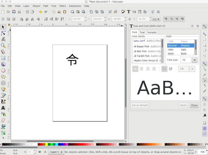
To generate G-Code characters by Inkscape, first, I input a character on the document board.
Next, I converted the character object to the path by using “Object to Path”.
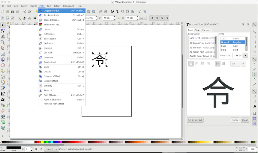
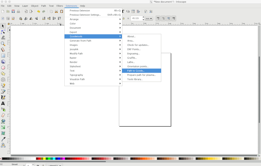
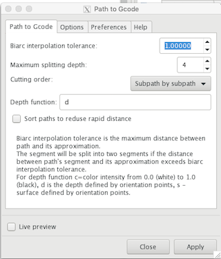
Then, I selected extension -> GCodetools -> Path to Gcode.
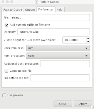
In the dialog of “Path to Gcode”, first, I opened “Preference” tab. Then, I set the file name and click “Apply” (Make sure to push this button, otherwise the G-code will not save the file that I set). Also, I set “Z safe height for G00 move over blank” to 10.000 (mm)
Then, I moved to “Path to Gcode” tab. Then, I pushed “Apply” button (here does not need to change the parameters).
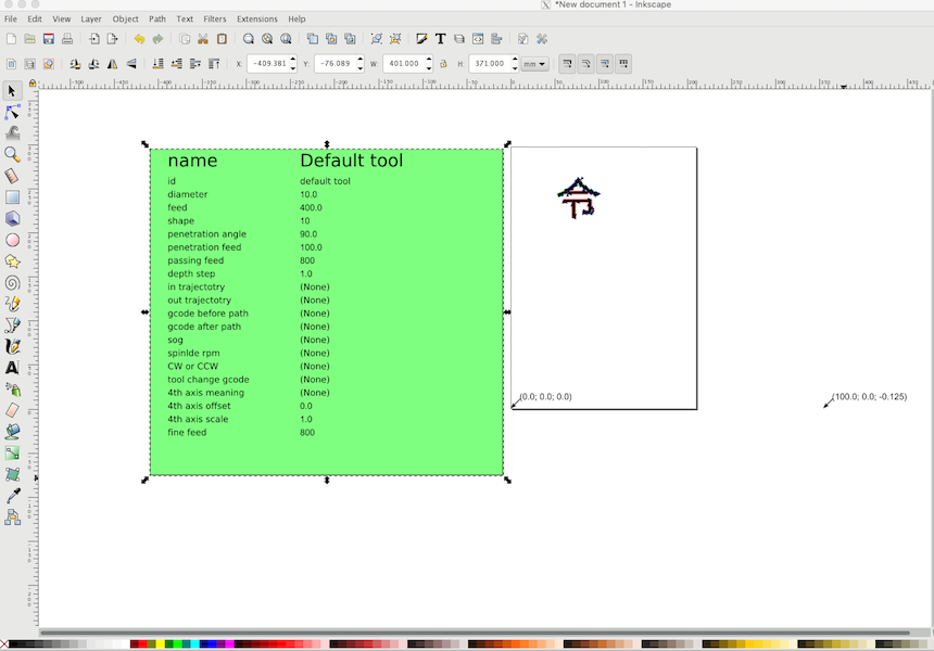
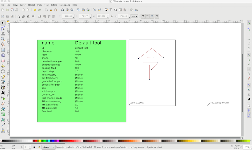
After that, G-Code file (rei_0001.ngc) is generated and each parameters are output on the Inkscape document.
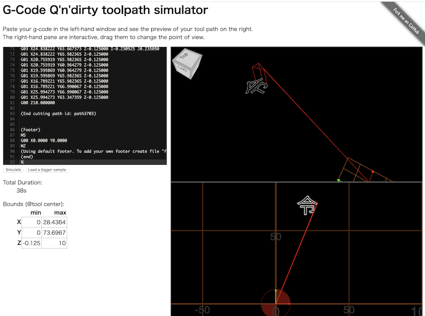
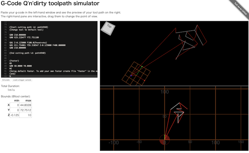
To check how does this geenrated G-Code works, I used a G-Code toolpath simulator. How to use G-Code generator? It is easy. We just paste the generated G-Code itself here. Then, I can confirm the result (how to move the machine and any other things…).
Problems
There are two problems I could find for generating G-Code by Inkscape.
Problem of Text-Font based character.
One is the probme of Text-Font based character. If we generate G-Code from text-Font based character (put the character and convert it to the path), it would be generated a G-code which is recorded outlines of the character. We want the machine write characters (not drawing characters). Moreover, stroke orders of Japanese (also Chinese) characters are very important to write. If we generate path from Text-based object, we cannot get the G-Code that considered these stroke orders.
Therefore, it is better to draw the path of the character with using “Draw freehand line” tool like the following. Drawing the line by stroke order, Inkscape can generates G-Code file that considered it.
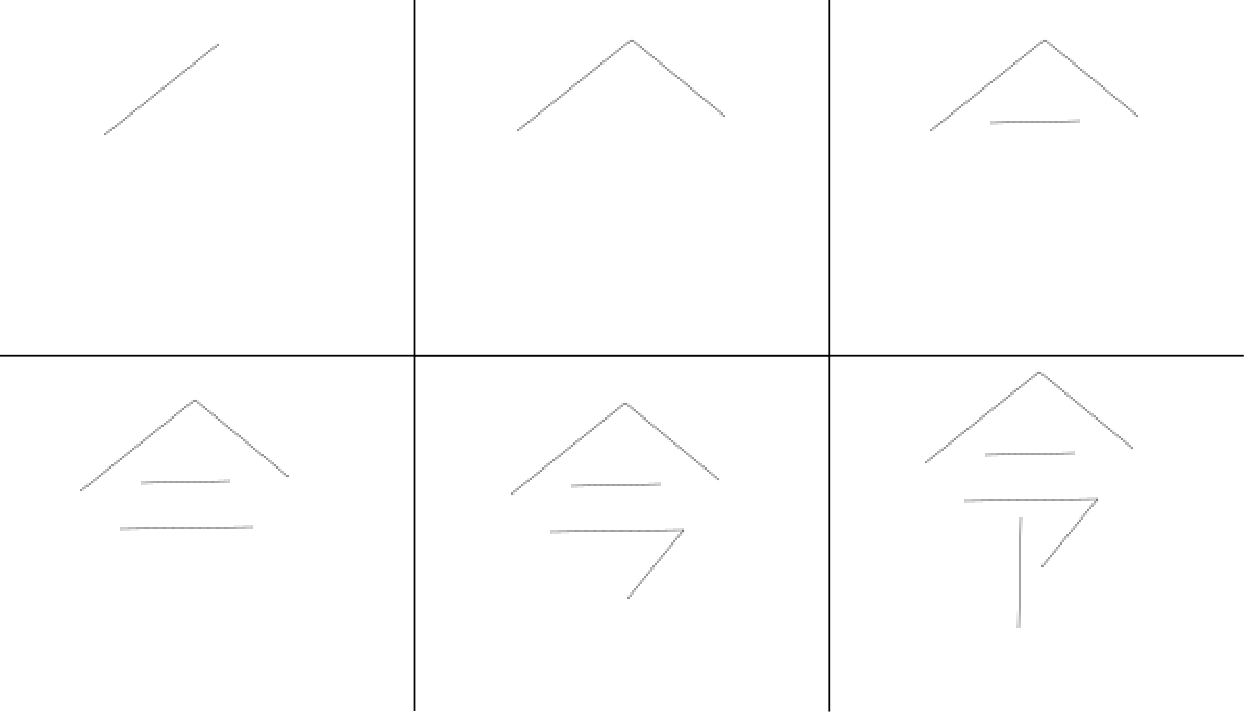
Then, generating the G-Code, and we can see the pathes are drawn in stroke order.
Problem of XY Origin
Another problem of generating G-Code is XY origin. When generating G-Code by Inkscape, XY origin is defined in Left Bottom side. On the other hand, the Core XY program mentioned above defined XY origin in Left Top side. The origin is different in Inkscape generation and the Core XY program.
As a result, the output of the character became mirror writing.
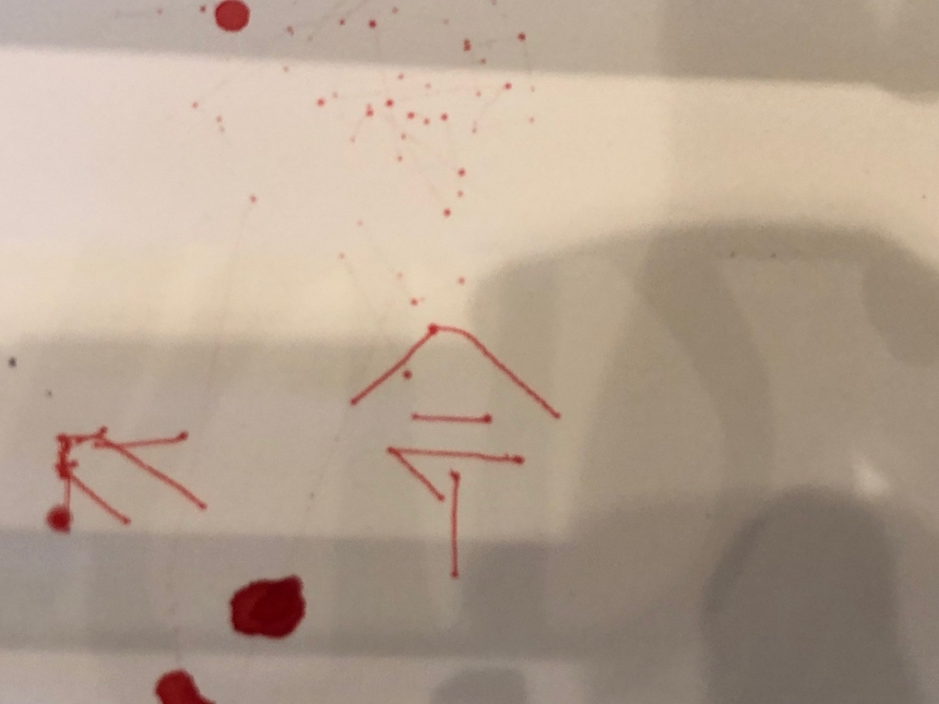
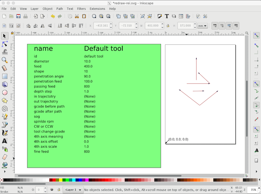
Therefore, I fliped the path veritically each path and generate again.
Interface Application
To send an original G-code file data that I generated by Inkscape, I used CNC Gcode Sender, based on Processing program.
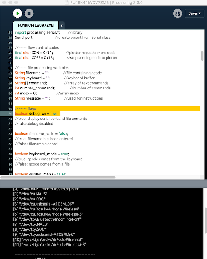
Before running the program, we have to detect which serial port are used for communicating with the machine. So, I started the program with debug mode with changing in line 69:
// ----- flags
boolean debug_on = true;
Then, we can see the list of the serial port on the PC. (It show the serial console windows in the Processing). For example, in my PC, serial ports are listed like below.
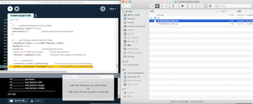
I found the No.9 (“dev/tty.usbserial-A105ML9K”) is the port connected to the Satshakit for the machine. Then, I changed the code in line 119. In details, I wrote “Serial.list()[x]” x=9.
  // ----- connect to the arduino
  if (debug_on) {
    printArray(Serial.list());
  }
  String arduino_port = Serial.list()[9];
  port = new Serial(this, arduino_port, 9600);
  port.clear();
I started to run the Processing program. Then, I could see a interface like below.
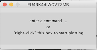
Following the directions, I moved the G-code to the foloder where this Processing program file are located. Then, type a G-Code file name and push “enter key”.
Then, I could work the machine as following my G-Code.