14. Networking and communications
This week is about networking and communications. one of the hardest topics. I learned how to communicate among different microcontrollers (transmit/receive data, control other micorocontrollers and so on) with various kinds of wired/wireless network protocols. Class video is here
Assignments
- individual assignment:
- design, build, and connect wired or wireless node(s) with network or bus addresses
- group assignment:
- send a message between two projects
Communication via I2C
My final project consists with two different part. One is multiple sensor devives, another is a controller of multiple serve motors. I want to communicate, control each other to make my robot more intelligence. This week, I focused on to I2C for communicating those different devices.
Checking sample board
First, as same with output device week, I checked whether the sample I2C master/slave boards would work as expected or not with using breadboards. I made master and slave boards and connect each others.
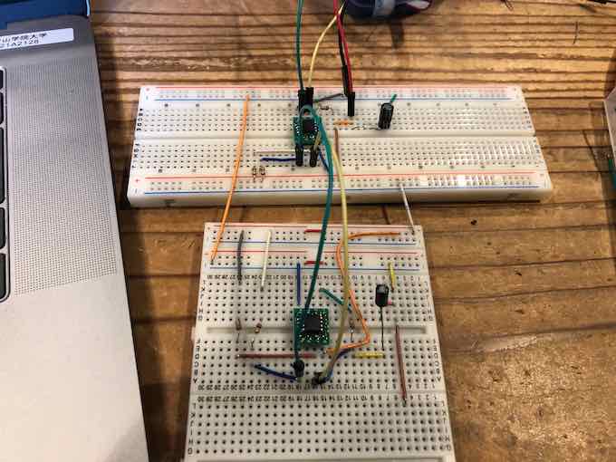
But, I could write any program on my ATTiny45. Checking sample boards carefully, I was found out PB1 is connected both MISO and MOSI. That’s because ISP didn’t works. So, I changed MOSI to connect to PB0, and finally ISP works and I wrote my sample programs.
Note on April 30
I confirmed it on April 25, and after that, as discussed class issue, master sample board is fixed but the slave sample board still does not fixed.
I wrote the following programs in Arduino:
- Transmit 0 or 1 number from master device to slave device.
- Slave device receive the number from the master
- Then, if the number is 1, LED blink, and the number is 0, LED would not blink.
I confirm the I2C communication will work well.
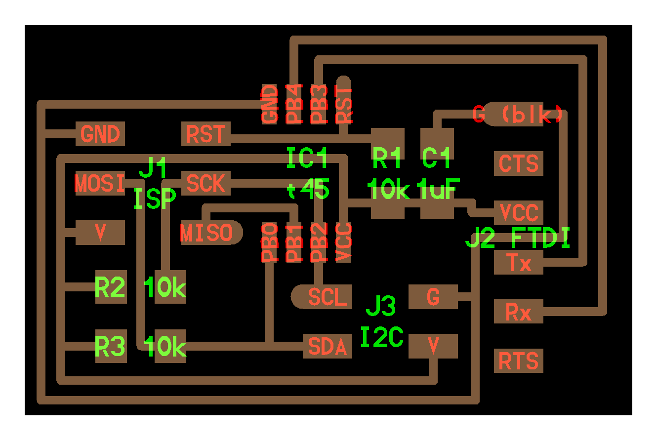
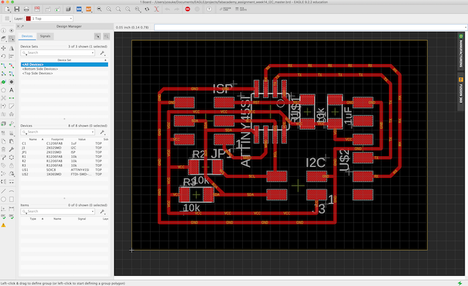
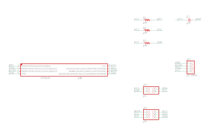
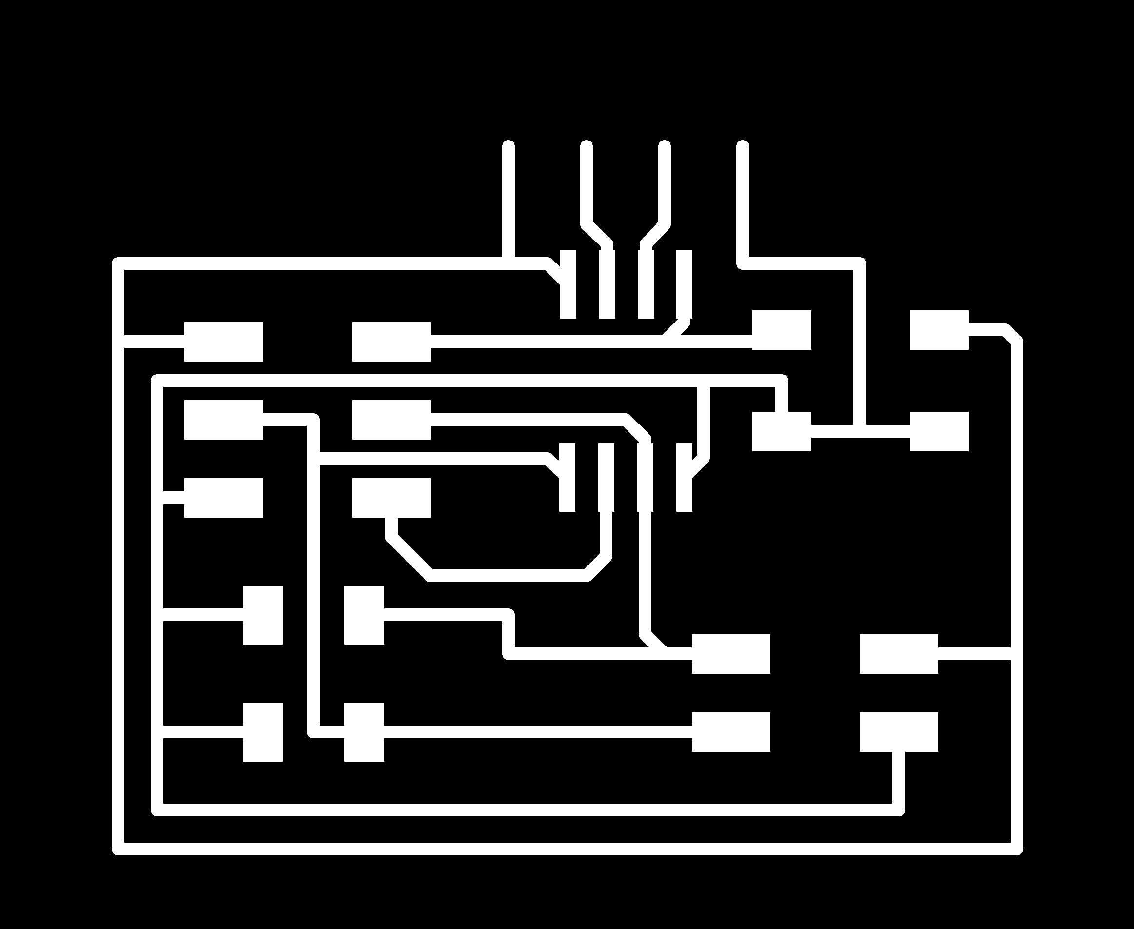
Designing each curcuit board.
I designed both master and slave devices on Autodesk Eagle. In master device, I re-draw sample board with fixing a mistake of sample board.
Master board
First, schema design of master board. The following equipments I used.
- ATTiny45
- 10K resister x 3
- 1uF Capaciter x 1
- 2x3 Jumper pin
- FTDI pin
- 2x2 I2C pin
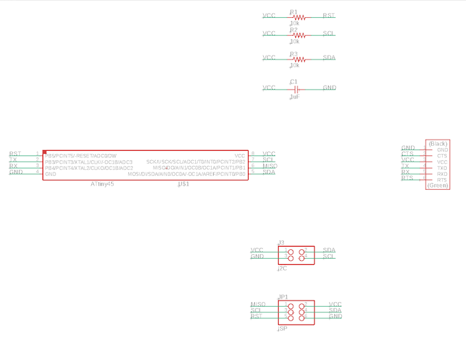
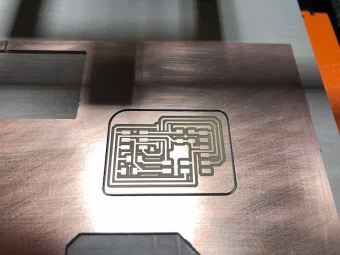
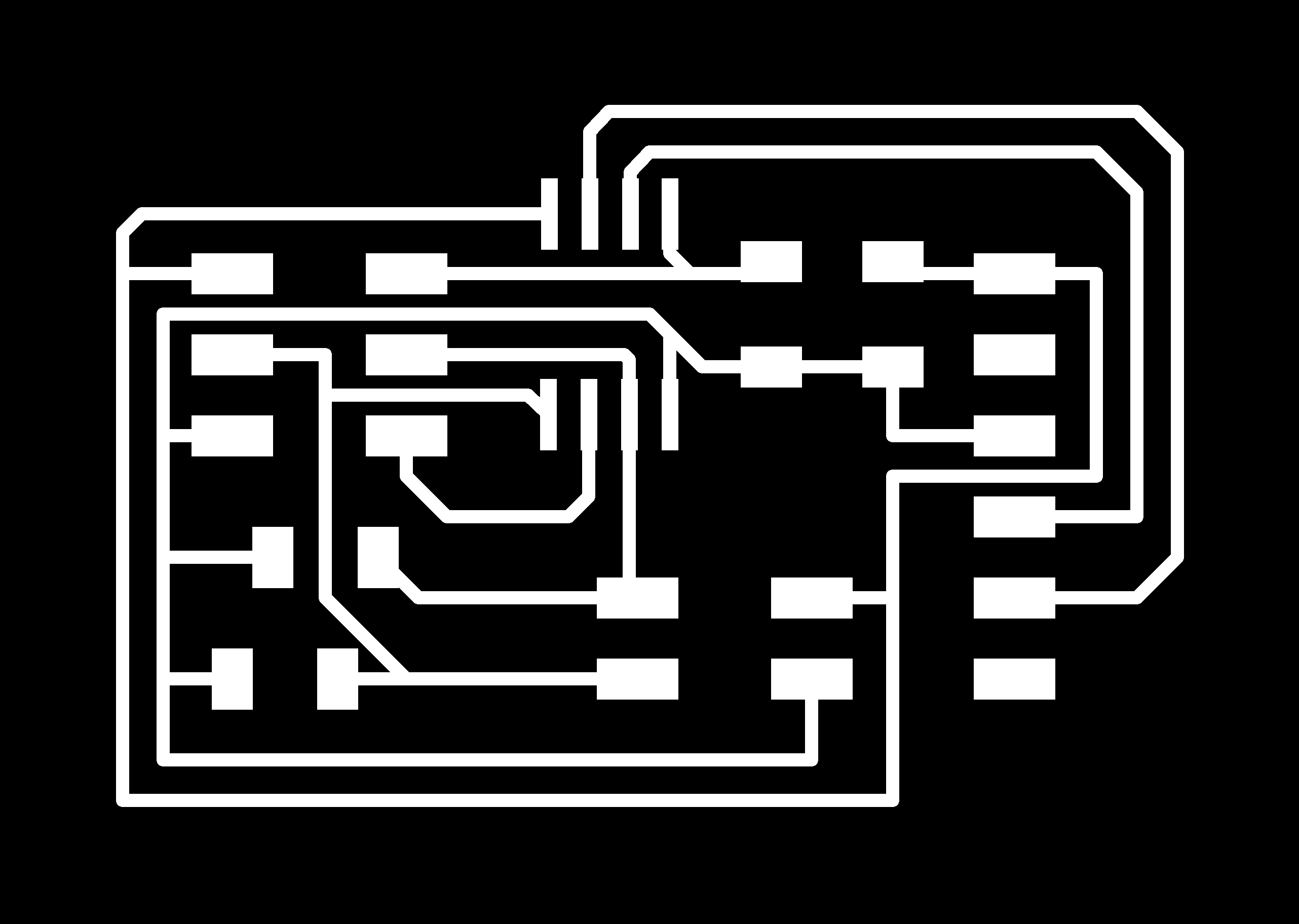
Here is the curcuit design of master board.
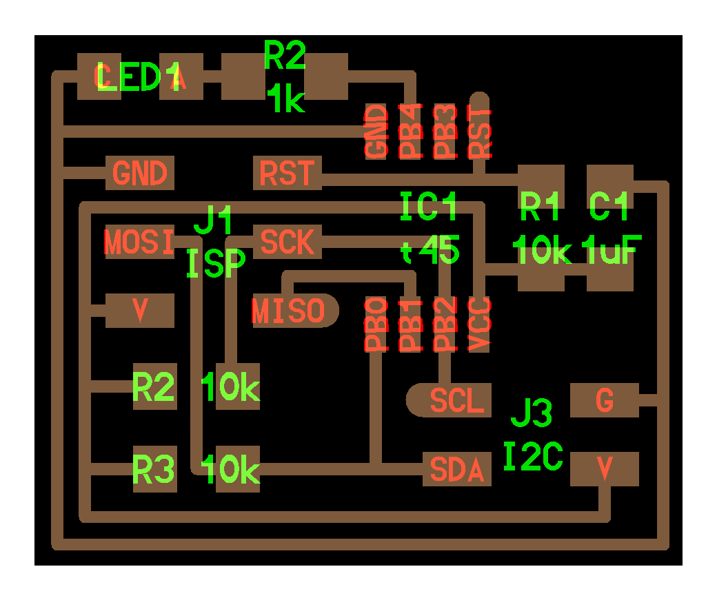
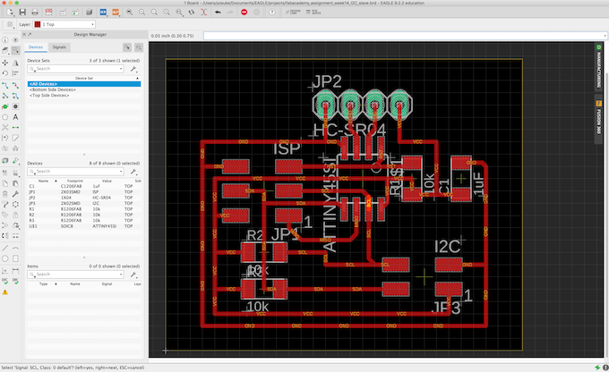
Slave Board
Next is to desiging slave board. In the sample of slave board, I found there are two Tiny pins are not used (PB3/PB4). I added 1x4 pins that can connect something to this slave board.
The following equipments I used for slave board:
- ATTiny45 x 1
- 10K register x 3
- 1uF Capaciter x 1
- 2x3 pin for ISP
- 2x2 pin for I2C
- 1x4 pin for connecting something
Here is the circuit design of slave board.
Then, exported png files of boards and import into mods to make CAM files for Roland-SRM20.
Milling and Soldering
The process of PCB with Roland SRM-20. I have already get used to do this process well.
First, milling the master board.
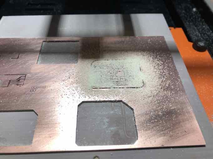
2nd, milling slave board.
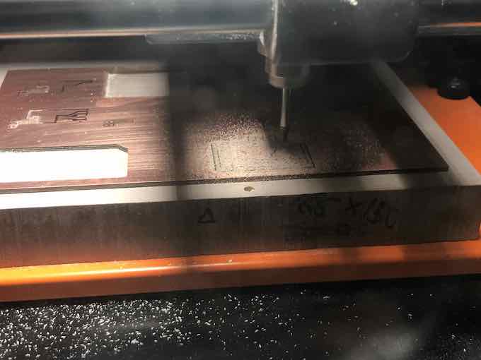
I could finish this PCB milling works in 1 hours.
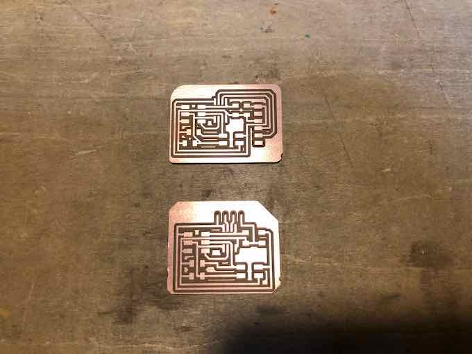
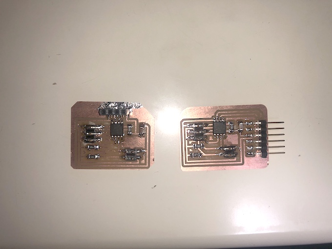
Finally, soldering equipments finhsied.
Trying to communicate - 1st try
To test the I2C communication works well, I wrote to transmit one byte character from slave to master.
First, connecting each board by cable.
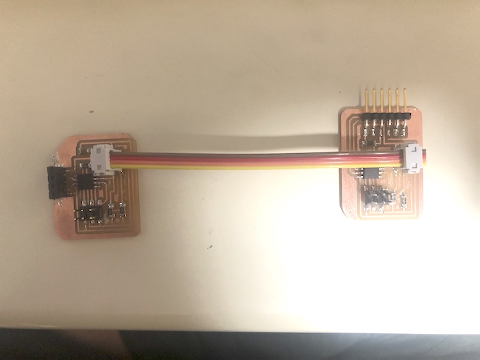
Then, in the master board, I wrote this program (requesting 1 byte data to slave and receive it).
#include <TinyWireM.h>
#include <SoftwareSerial.h>
#include <USI_TWI_Master.h>

SoftwareSerial ss(3,4);

void setup() {
  // put your setup code here, to run once:
  TinyWireM.begin();
  pinMode(3,INPUT);
  pinMode(4,OUTPUT);
  ss.begin(9600);
  //mySerial.println("Hello!");

}

void loop() {

  TinyWireM.requestFrom(0x4,1);
  //uint8_t recv_d;
  //uint8_t bytes[4];

  while(TinyWireM.available()){

    uint8_t c = TinyWireM.receive();
    ss.print((char)c);

  }


  delay(500);

}
TinyWireM and TinyWireS use uint8_t for transmitt/receive data between slave and master. Therefore, the data that are transmitted from slave should be converted to uint8_t. Also, the data that the master receive from slave should be converted from uint8_t to suitable data type.
Also, in the slave board, I wrote this program (recieving request from the master and reply one character).
#include <TinyWireS.h>
#define I2C_SLAVE_ADDRESS 0x4

#include <avr/io.h>
#include <util/delay.h>

void setup() {
  // put your setup code here, to run once:

  TinyWireS.begin(I2C_SLAVE_ADDRESS);
  TinyWireS.onRequest(requestEvent);

}


void loop() {
  // put your main code here, to run repatedly:

}


void requestEvent(){

  char c = 'A';
  TinyWireS.send(c);

}
Make sure the following libraries are required for I2C program in Arduino.
- TinyWireM
- TinyWireS
Then, I checked whether the master board receive character “A” and output to the serial TX (and Arduino Serial monitor displayed this “A”).
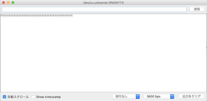
… It doesn’t work well.
Debugging
To check whether the problems could be on I2C communications, I used Arduino UNO. First, I connected Slave I2C port to Arduino UNO, then I wrote Arduino Wire sample sketch for sending one byte character. Then I checked the Master board could catch the “A” from my slave board.
It works well, and I could find that hardware/software of I2C communication on the slave board is not the problem.
Next, I connected I2C port of the master board to Arduino UNO. And, I wrote the sketch for slave board (send “A” character to master). Moreover, I wrote on the Arduino UNO a sketch working as master device catching one byte character from the slave. Then, I checked the Arduino UNO could catch the “A” from the master (works temporaly as slave).
It also works well. From those result, I could find the I2C communication of both my master and slave boards does works, and the problem is not there.
So, I checked whether anything wrong in my programs, with checking imported libraries. Then, I found this site. This site is the something like a tutorial page for TinyWireM libraries. The descriptions are for ATTiny85, but I thought these issues would be apply to ATTiny45.
In this tutorial page, I found this sentence:
By default the I2C master library (TinyWireM) is set to run at 1MHz. To run at 8MHz, #defines in USI_TWI_Master.h / .cpp must be changed. No changes are necessary for the I2C slave library (TinyWireS).
Checked my Arduino configuration, I found it is build by Internal 8MHz. So, I changed here to Internal 1MHz and build master board and write the program, again. Then, tried to communicate again.
It works well…!
Transmit Multiple byte data
To transmit multiple byte data, it should be divided into one byte unit with converting to uint8_t data type and transmit one by one. It should be implemented in the slave side for transmission.
I revised slave code to here:
#include <TinyWireS.h>
//#include <SoftwareSerial.h>
#define I2C_SLAVE_ADDRESS 0x4

#include <avr/io.h>
#include <util/delay.h>

volatile uint8_t i2c_regs[] = {
  'H',
  'E',
  'L',
  'L',
  'O',
  ' ',
};

volatile byte reg_position = 0;
const byte reg_size = sizeof(i2c_regs);

void setup() {
  // put your setup code here, to run once:
  pinMode(trg, OUTPUT);
  pinMode(ech, INPUT);

  TinyWireS.begin(I2C_SLAVE_ADDRESS);
  TinyWireS.onRequest(requestEvent);
  //ss.begin(9600);
}


void loop() {
  // put your main code here, to run repatedly:
}


void requestEvent(){

  int n = reg_size - reg_position;
  for(int i = reg_position; i< n; i++){
    TinyWireS.send(i2c_regs[reg_position]);
    reg_position++;
    if(reg_position >= reg_size){
      reg_position = 0;
    }
  }


}
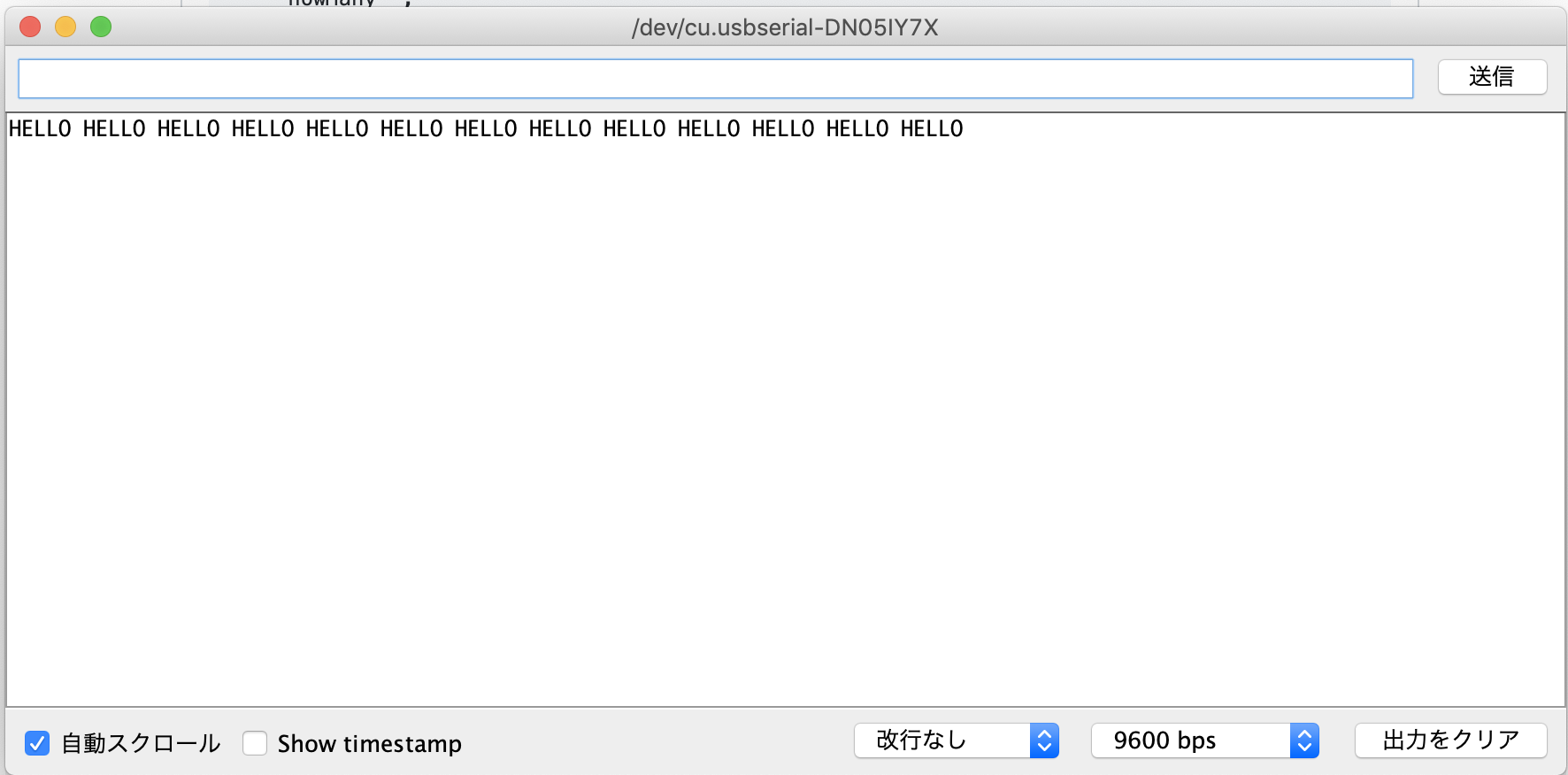
And, the result is here:
Week 14 files
- I2C master board
- I2C slave board
- Source Codes