7. Electronics design#
Group Assignment: use the test equipment in your lab to observe the operation of a microcontroller circuit board
Lab Test Equipment#
Multimeter#
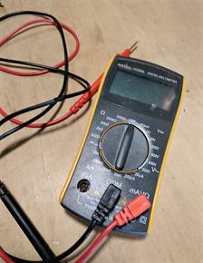
Uses:
- Check conductivity of trace & connections: we have been using the multimeter for this purpose since the very first PCB we constructed…checking to make sure that our solder joints are good by probing it and the copper trace that leads from it.
- Check polarity of components requiring correct polarity orientation
- Check power to the board
- Measure current…be careful how to do this without damaging the tester…do not create a short circuit with the probes
Testing electrify:
We can use multimeter to check whether the circuit is correctly elecrify. For example, if you want to check the micro controller is electrified:
- Set a plus of multimeter on a joint of the pin of the micro controller.
- Set GND of multimeter on the circuit that is connected to the pin
grp07_multimeter from Yosuke Tsuchiya on Vimeo.
If it is elecrified, the multimetor buzz and the display show something reaction.
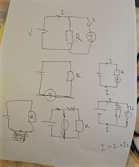
Testing value of register:
We can also use multimeter for checking the value of register.
grp07_multimeter_2 from Yosuke Tsuchiya on Vimeo.
Testing voltage:
We also can use multimeter for checking the value of voltage.
grp07_multimeter_3 from Yosuke Tsuchiya on Vimeo.
Digital Oscilloscope#
Tectronix TBS 1052B Digital Oscilloscope
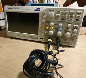
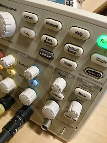
- When the multimeter is not enough to…use the digital oscilloscope
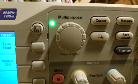
- Calibrate the Oscilloscope before use…touch a signal probe to the metal tester tabs at the lower right of the machine and observe a signal image
- This Oscilloscope has 2 channels and can measure up to 2 signals simultaneously
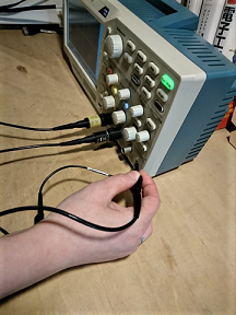
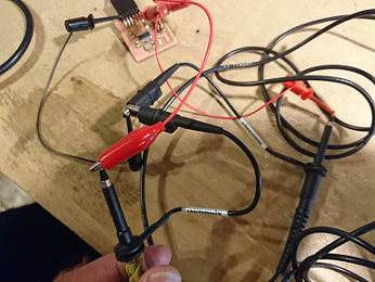
- Each signal probe has a ground clip and a probe
Testing:#
- Rx probe…one-time signal observation
- Crystal probe…constant signal observation
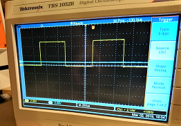
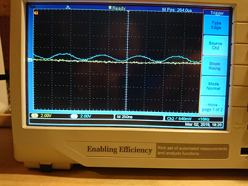
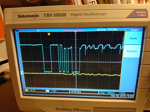
Testing the resonator on the “Hello World” FTDI PCB with the help of a lab instructor. She adjusted the horizontal time scale to fit the high frequency of 20MHz. She also adjusted the trigger level…because, the vertical level (voltage) was higher than the sine wave, so the oscilloscope could not detect the frequency automatically.
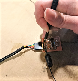
- Hello program signal observation
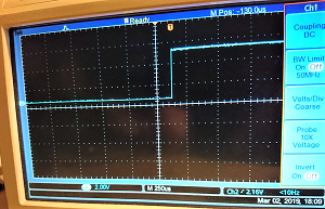
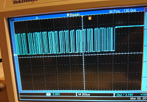
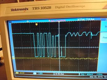
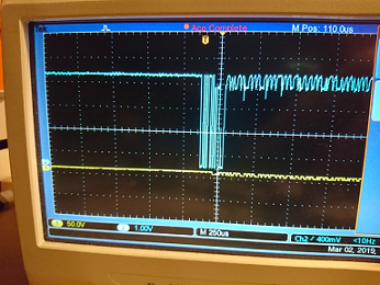
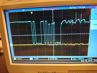
Wired the FTDI board to the oscilloscope…connecting signal probes to the Tx and Rx pins.
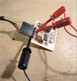
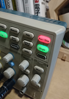
Pushed the ‘Signal’ button to capture the signal from keystroke…allowing viewing adjustment of the signal image
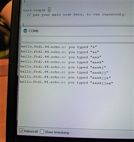
Entered one keystroke at a time into the Arduino IDE and observe the resulting signal on the Oscilloscope. Each letter generates a unique signal image. There was also something that looks like signal noise after each character signal that we generated that we don’t understand.
Some videos to get us a better understanding of the testing equipment…
Multimeter Basics:
Tektronix TBS 1052B Basics:
How not to blow up your digital oscilloscope…the dangers of short circuiting