8. Computer controlled machining#
group assignment: test runout, alignment, speeds, feeds, and toolpaths for your machine
CNC and material#
We did the group assignment using SHOPBOT of TechShop Tokyo.
CNC machine#

- Model Name: SHOPBOT Full-Size 10151
- Cutting Platform Size: X 1300mm / Y 1200mm / Z 150mm (Z depends on the length of end mill)
- Material Capability: Plywood, MDF, Soft & Hardwood…seemingly every milling material except metal or anything that requires cutting lubrication
- Data Format: gcode
An English language Shopbot User’s Guide PDF is here
- Gcode (tool path) Generation Software:3D-CAM, VCarve, Fusion360 (we used Vcarve)
- Data Format(2D): svg, dxf, dwg, eps, ai, pdf, skp
- Data Format(3D): stl, obj
Key Components of Shopbot
Milling Head: High speed rotating spindle witha collette to hold various types of end mill bits…we used a 1/4” down cut endmill for all our cutting

Hand Controller: 3 button physical control box for the Shopbot… - Emergency Stop Button - Reset Button - Start Button

Dust Collector: Removes the majority of milled material via a vacuum system. This dust collector collar is attached to the Milling head area after the z-origin is set. (the vacuum system is loud and usually turned off…and must be turned on prior to milling start)

Machine Control Switches: 3 key switches…Emergency Stop button, Machine On/Off Switch, Spindle Lock/Unlock key switch (disallows/allows milling head spindle rotation)

Material
- Lumber core plywood
- Sheet Size: 1220mm x 1210mm x 15mm

- Vendor: Hokurei Wood
Design test parts#
To complete the group assignment for the week, we created models of joint parts that will be used for some pf the individual project for tests.
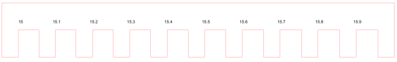
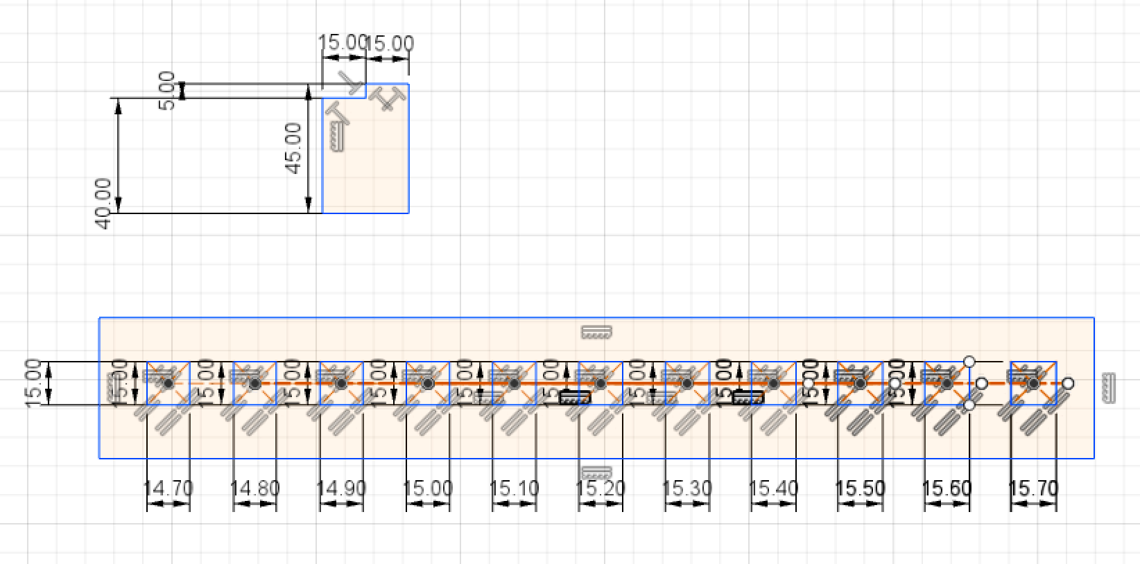
1. Press-fit Kit Type
2. Pocket Type
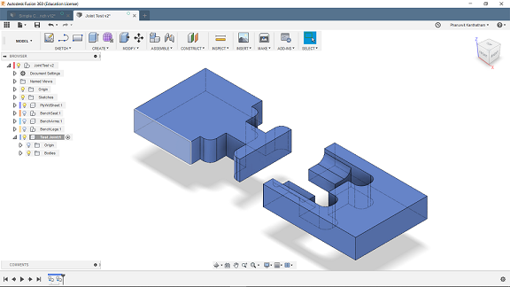
3. 3D joint type
Create data file#
We created the data file for the Shopbot using VCarve software. The VCarve was available for use on TechShop PCs, so we did have install it to our PCs.
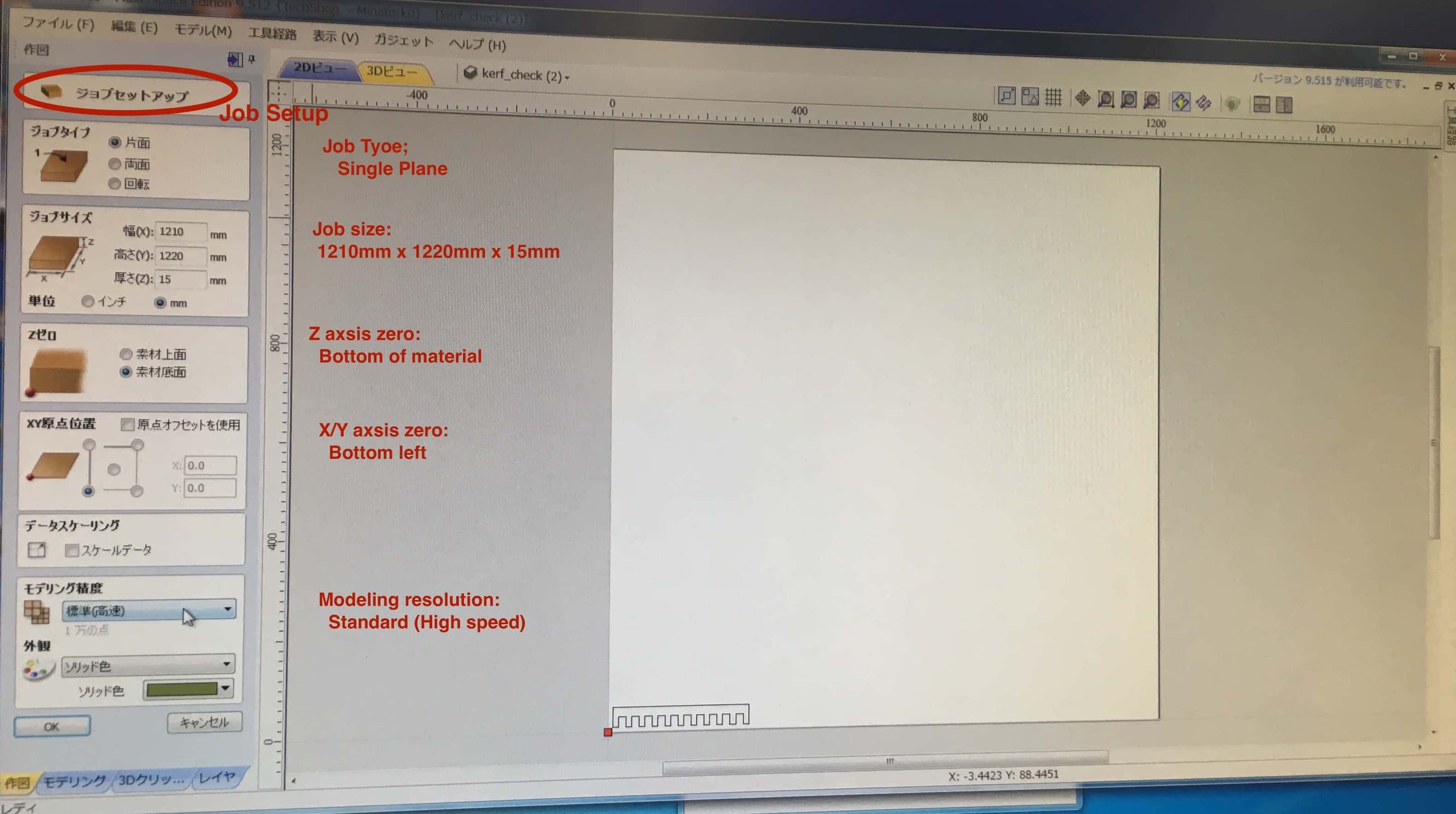
Job Setup#
Set the parameters of the job first in the “Job Setup” screen.
- Job Type: Single Sided / Double Sided
- Job size, thickness
- Z Zero Position: Both Material Surface Location and Machine Bed location
- XY Datum Position
- Units: inch/mm
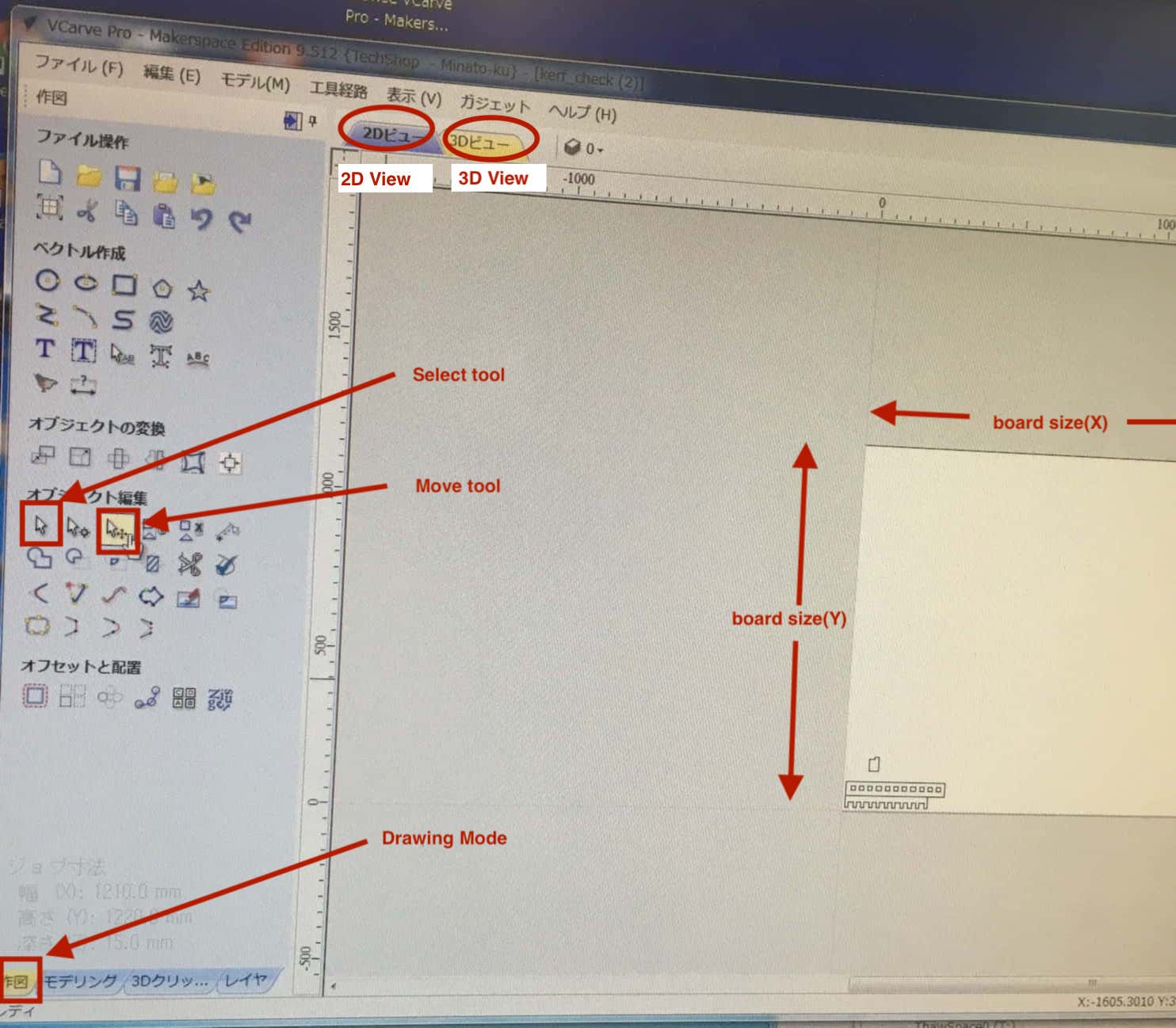
Arrange image files#
We imported 2D and 3D images together to the same file.
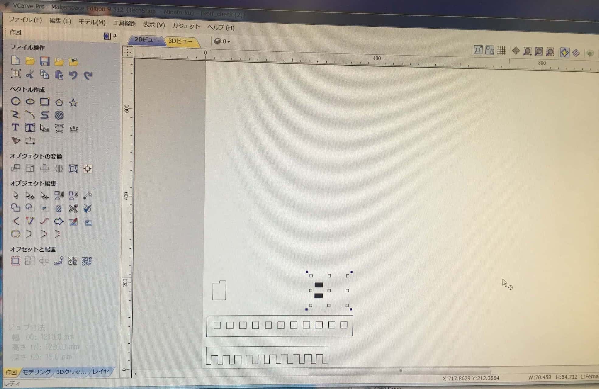
- Import 2D files (svg and dxf) to the window and move them to the proper position.
- Add Dog bone to corners of 2D image using the Vcarve software

- Import 3D file(STL) to 3D view
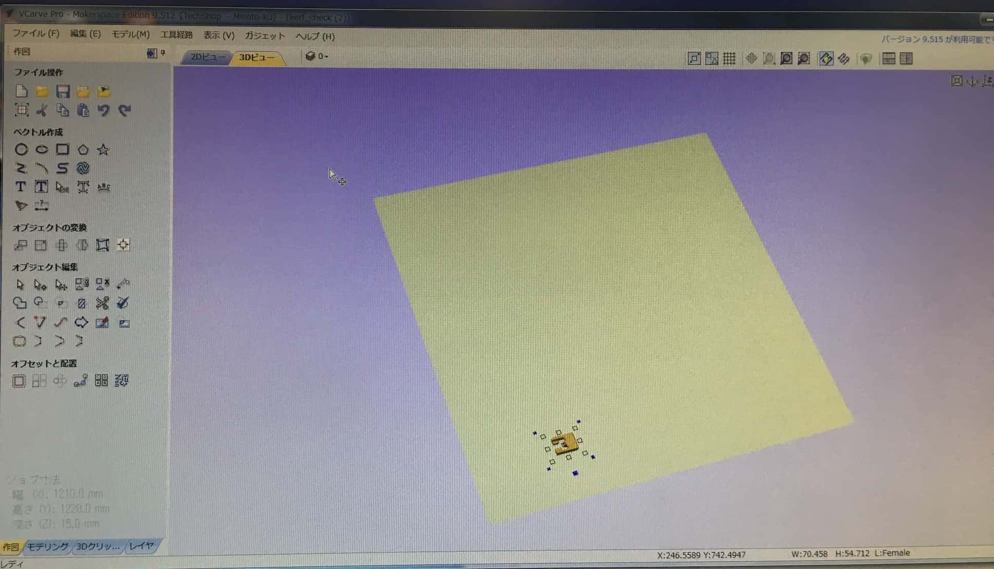
 …learned that we needed to created a vector outline for the 3D object via different tools than for 2D


2D Profile Tool path#
2D profile machining is used to cut along a vector.
Parameters
- Cut Depth: board thickness (15mm in our case) + 0.5mm = 15.5mm
- Tool: Down-cut(57-910) Endmill, Speed 12,000 RPM (Spindle Rotation Speed), Feed 3.0inch/second
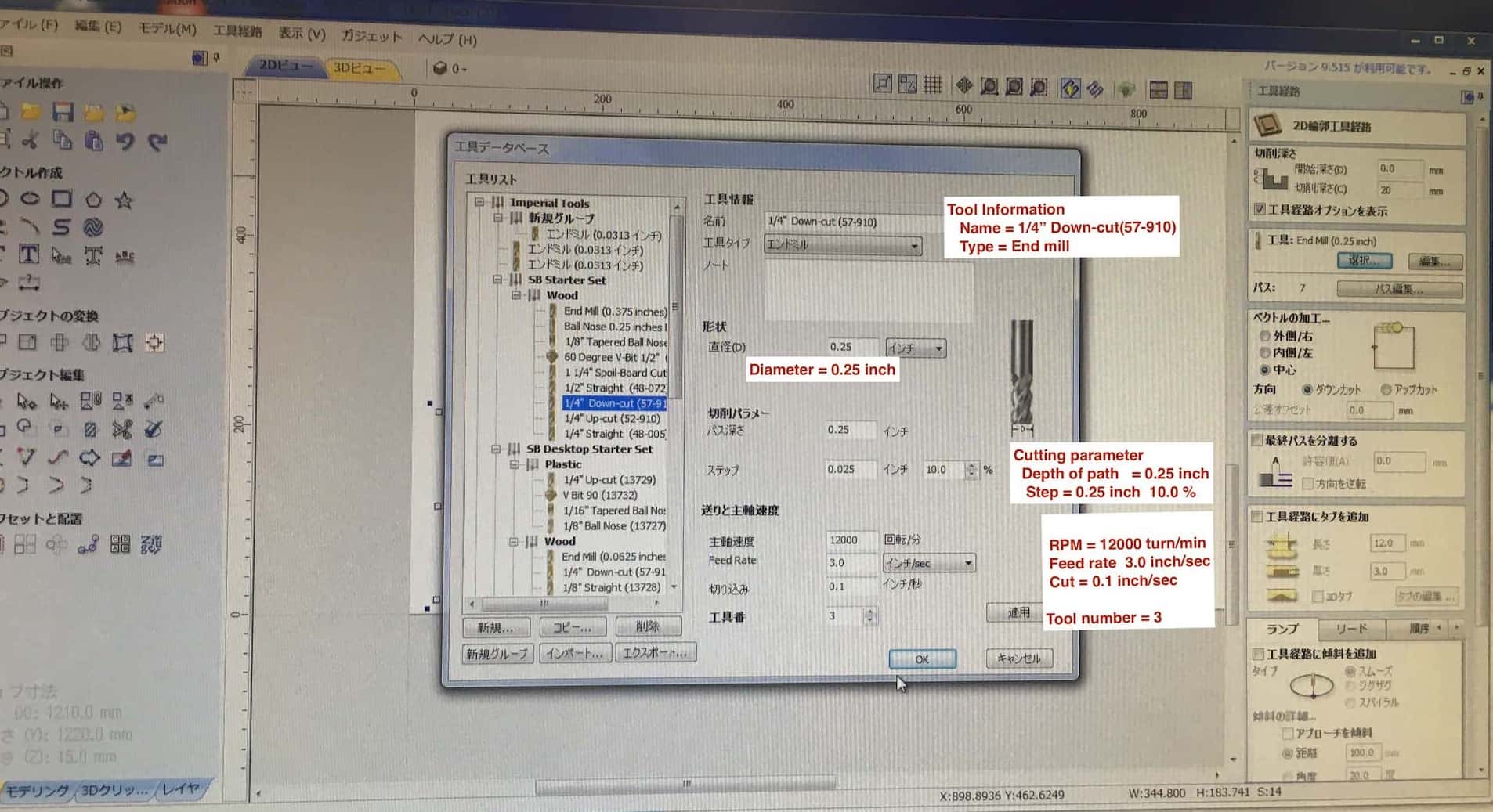
- Vector Processing: outer/inner / center
- Direction: Down cut / Up cut
- Add Tabs to toolpath (can be manual or automatic)

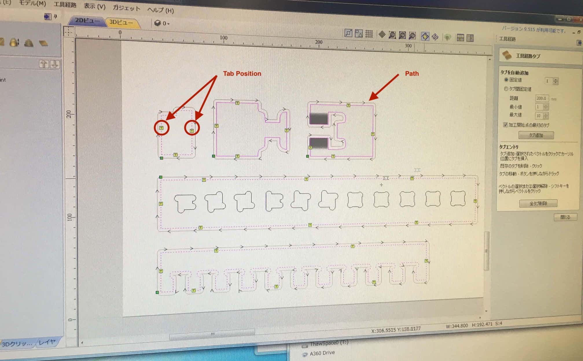
2D Tool path#
Outline Milling:
- Select Outline Milling
- Input cut depth 15.5mm
- Input number of passes to cut outline…3
- Check box to add tabs

Interior Depression Milling:
- Select Interior “Pocket” milling
- Input pocket depth (this image shows 7.5mm but we changed to 4.0mm for the 2D test part)
- Select the Endmill
- Select the number of passes to cut the Pocket
- Select cut path for pocket…work from inside to outside of pocket hole

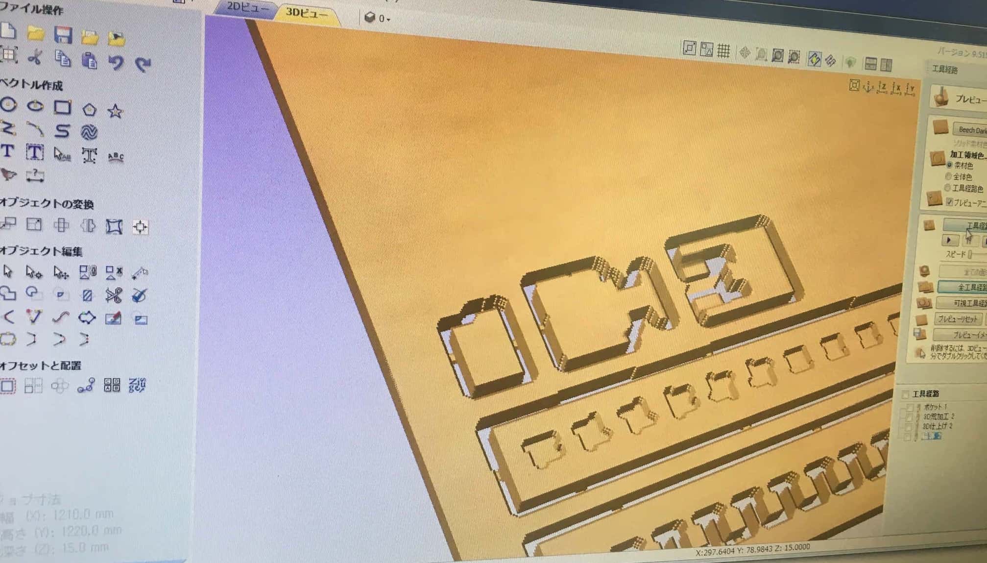
3D Tool path#
- Path generation looked good
- We did not understand that the blue color over the 3D parts would mean that a layer of the top surface would be milled away (error in generating gcode?)


Preview#
virtual 3D preview of the cut file can be viewed as a video. Even though we adjusted the speed of the video to slowest…the virtual cut action was too fast to observe with any usefulness.

Save files#
Estimate of machining times for all tool paths shown…
Mistake made…wrong endmill (ball head) selected that increased cut time significantly!!!

New estimated time after endmill selection corrected…

-
It is possible to change the order of the parts cut

-
Save files

Milling#
Multi-step procedure to actually mill.
- Set Milling machine XY origin…automatically by pushing the set XY Button
- Set Z origin…requires the use of a conductivity plate (and two people…one to hold the plate the other to work the PC controls)…the end mill slow moves down and touches a metal place put flat on top of the sacrificial layer (conductivity must be tested before running z origin set by touching the metal plate to the end mill tip)
- Fix the material to the sacrificial layer using air gun driven plastic fixing pins(?)
- Change z-origin temporary to a location at least 50mm above the material and setting this to Zero
- Run an “Air Pass” of the tool path file to observe any strange milling behavior, when satisfied…move on to actual Milling
- Reset z-origin back to actual Zero
- Start the milling process…
- Turn on Dust collector
- Dis-engage spindle lock by turning the Key
- Run the cut file, spin up the Spindle
- Click OK to mill
- Observe the milling process attentively from beginning to end…be ready to hit the emergency stop button if any issues arises
Test results#
Tool Path & Alignment Visually examining the milling results, we observed…
- Tool paths were accurate to that displayed in Vcarve software, without significant visible deviations…rectilinear angles look good
- The cut depth of the 2D parts slots appeared deeper than specified 4mm (runout issue?)

- The 1/4” endmill may not have been ideal for the tight spaces in the 3D parts…leaving rough edges every where
- Also a weird issue with the top surface of the 3D part being milled off by approximately 1mm


Speed & Feed Consulted Shopbot Manual for recommended Speed & Feed…links to the PDF file here. The TechShop settings for RPM and Chip Load for their Shopbot was within the recommended range for Plywood.
- Results were reasonably good…with ugly bottom edges to cut pieces that resulted the use of a down cut endmill.
- We noted that the 1/4” downcut endmill had some trouble with tight corners and radiused down sloping shapes in the 3D joint…perhaps a smaller diameter endmill would be better for the narrow spaces and a ball-end endmill for the radius cuts. Lack of time meant that we were not able to explore these options this time.
- We also observed some error in the way we produced the 3D cut file (z-setting error?) as those shapes had about 1mm of its top surfaced milled away.


Runout
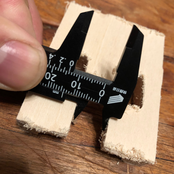
2D Part Tests: We assembled milled 2D parts, the results as follows…
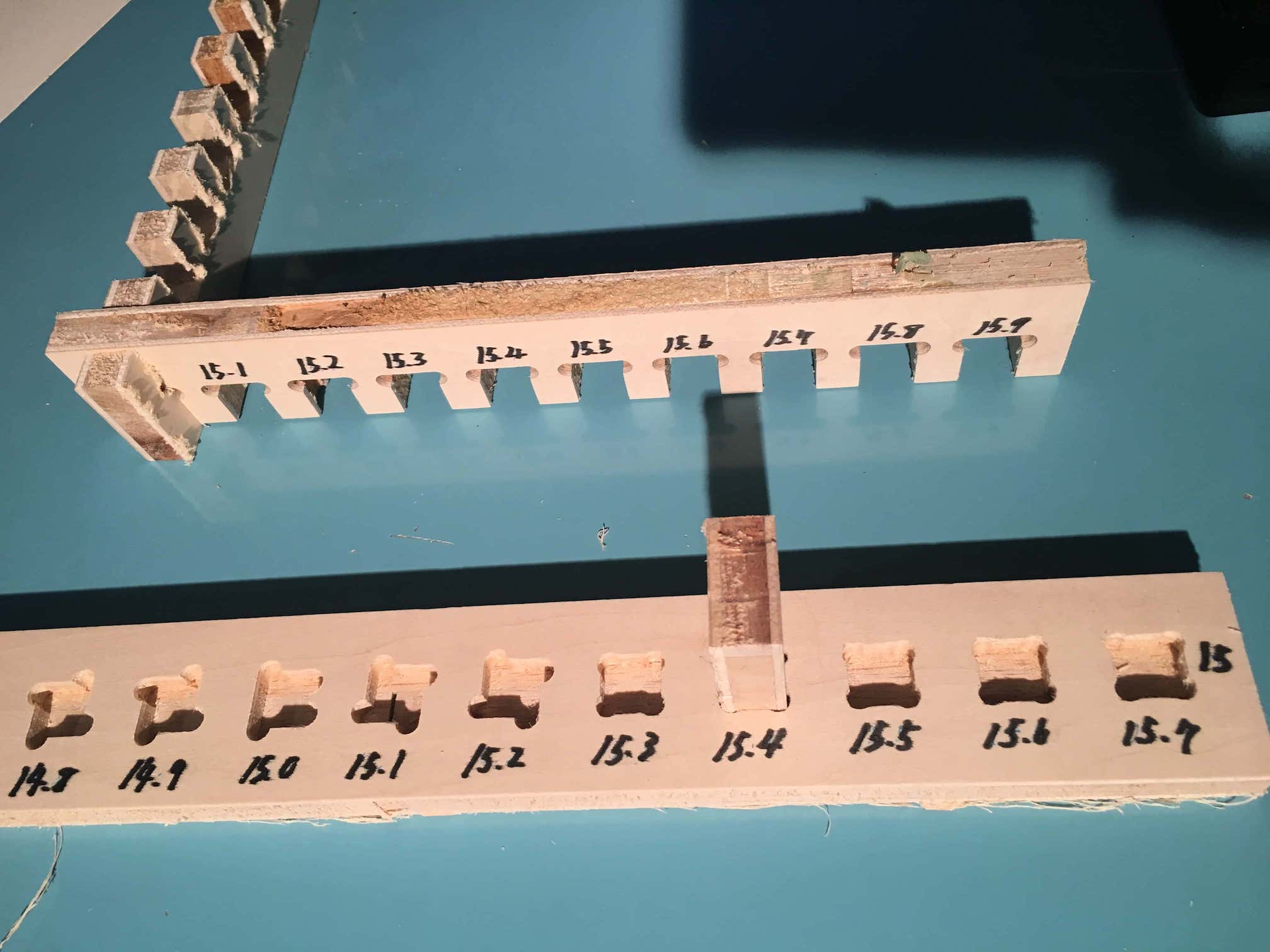
- Negative to Negative Fit Test:
-
15.0mm into 15.0mm…same runout for both cut gap…inconclusive results
-
Positive to Negative Fit Test:
- 15mm square positive part fits best into 15.4mm square negative hole…implying runout of 4.0mm
3D Part Test:
We measured the actual cut sizes of the 3D joint versus the CAD model, the results as follows…
Positive Material Width: - CAD Dimension: 15.0mm - Milled Dimension: 16.4mm - Runout: 1.4mm
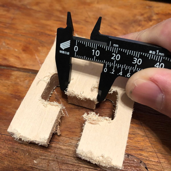
Negative material width: - CAD Dimension: 15mm - Milled Dimension: 14.0mm - Runout: 1.0mm