Week 20
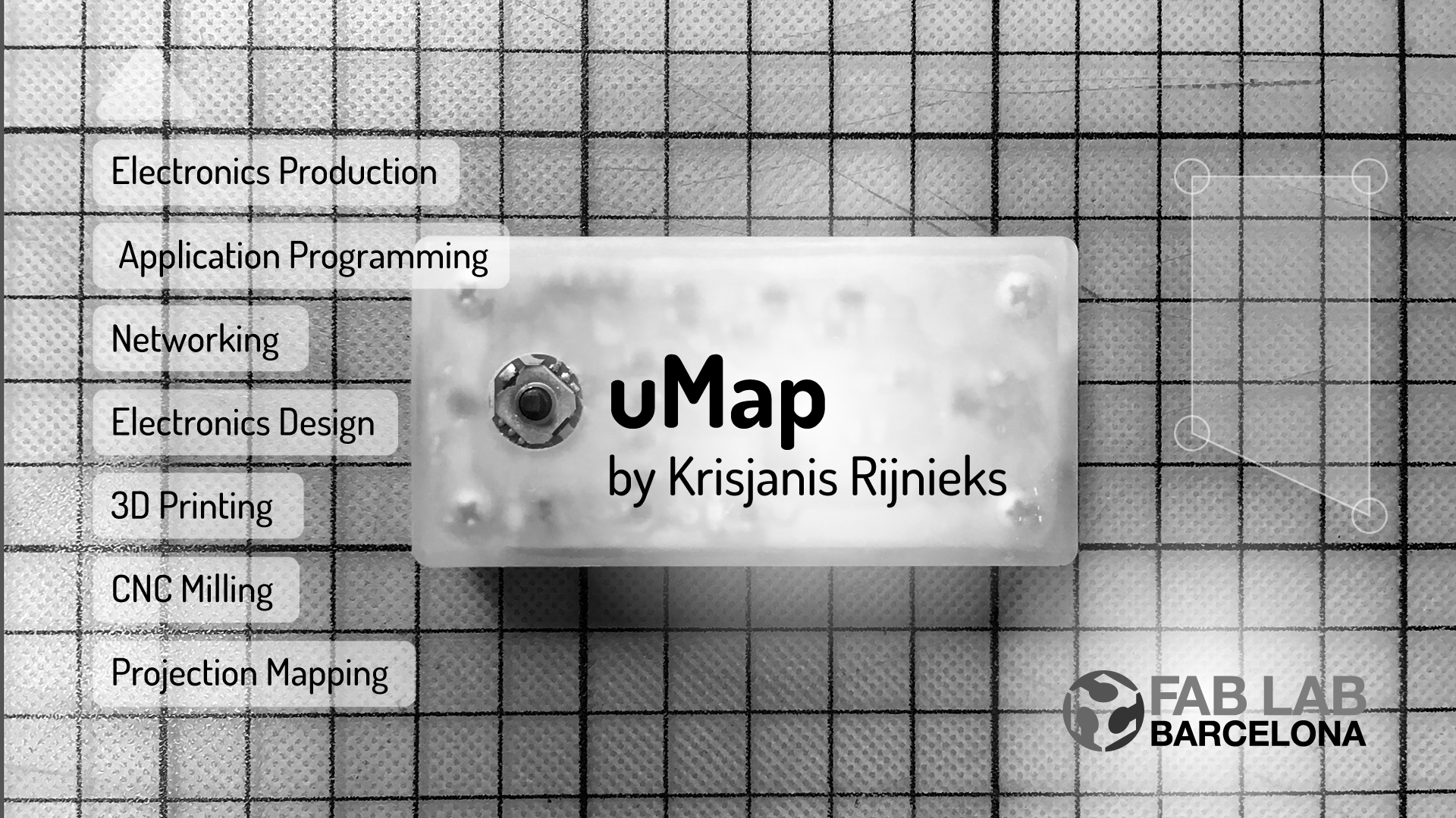
This section contains the story about the development of my final project. You can find introduction and initial documentation of the uMap device on the Final Project page. Below you can see the final project presentation slide.
And here is my last minute video that I made to support the presentation of my final project.
uMap is a minimal device for projection mapping installations. It can be connected to a projector by using a HDMI cable. Texture of real-life objects can be changed in a precise manner by using the combination of uMap and a projector.
It has three levels of complexity that:
- Maintainer level let’s one use the integrated joystick button for minor projection mapping adjustments.
- Artist level offers the web interface to create a projection mapping composition by using images and videos as textures.
- Pro level where one can use open source software and design files to adjust uMap to whatever it has to be adjusted.
uMap is the hardware version of the open source projection mapping software ofxPiMapper. It started out as an experiment to replace the use of expensive computers for projection mapping installations. Not everybody can afford to leave one’s computer at a venue for even a week. Rental and purchasing might not be options. uMap aims to be an affordable and hackable media player for projectin mapping instalations.
The Process
I am continuing to write this a few months after I finished writing the Advanced Challenge section. The project is moving forward. At the point I am working on a web-based remote control solution for the Interface and Application Programming week.
However, the idea and roadmap of the project have become more clear. I tried to design the first version of the housing during the Computer-Aided Design week, but realized that I have to do more work on the electronics part of the project before.
During the Molding and Casting week I had a similar thought as I wanted to design the mold for the housing and cast it. Here I had the same problem as before (electronics) and the molding technique proposed for the course was not really fitting my project. Injection molding is something I would like to do instead. I am looking forward to try the way proposed by Precious Plastic. Using it would give the project an interesting conceptual twist as well.
Another way to build the first version of the housing would be using 3D printing. I am looking forward to use the Formlabs printer with the Tough resin type. I have seen parts made this way and I know this would work well for what I want to create. But as said before, I have to sort out the electronics first.
Electronics
Initially I thought that it would be just enough to connect the 5-Way Tactile Switch to the Raspberry Pi GPIO pins directly. However the assignments forced me to use a microcontroller in-between, which is not necessarily a bad nor a good thing. However it would allow me to modularize the solution so that input processing happens on the microcontroller and Raspberry Pi receives clear messages.
Below you can see a video of the work done during the Input Devices week, a 5-Way Tactile Switch board is being used to select corner vertices (center press) of a quad surface and move them around (left, right, up, down).
In the video above I used a Mac OS as the platform to run the projection mapping application. The goal, however, is to use the Raspberry Pi. The next step during the Output Devices week included designing a board in a way that it would be connected to the Raspberry Pi GPIO pins.
I managed to break the switch in this attempt, but in the video below you can see how it looks and that the output device (5V vibration motor) is working.
I was waiting for the actual 5-way switch components to arrive from Mouser Electronics. When they were finally there, I started working on the Raspberry Pi Zero HAT board, taking into account the actual measurements and pin lauyout of the Raspberry Pi board. This is how version 0.1.0 looked like.
This was mostly an attempt to make a double-sided board. The electronics design did not allow to properly debug the board, it was missing a single LED that could be programmed to blink whenever the button is pressed. Id did not have a power LED to quickly make sure if the board receives power or not. Nor it had anything to convert 5V TX and RX signals to 3.3V required for the GPIO pins of the Raspbery Pi.
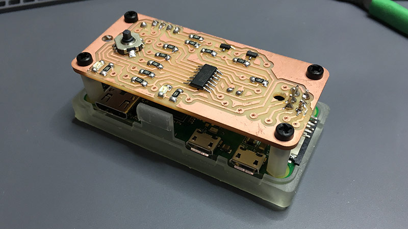
For the version 0.2.0 I tried to solve all the beforementioned problems and add a vibration motor to improve the feel of the device. Surprisingly it did take less attempts (one) than it was with v0.1.0. Below is a list what was added.
5Vto3.3Vlevel shifters- Power LED
- Debug LED
- Vibration motor
- Moved ISP header
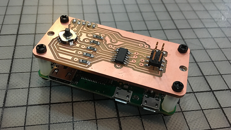
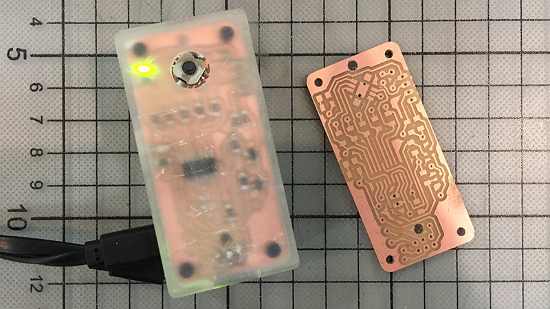
And the following is an image of the board with components on it and 100% connected to everything.
Surprisingly everything worked out of the box and I was soon able to receive serial messages on the Raspbery Pi. I was able to blink the programmable LED and drive the vibration motor. I decided to mill another copy of the board to have a backup copy just in case. At this point I could focus on the housing of the project.
Housing
Housing for the uMap project was supposed to be one of the most exciting parts as one of my personal goals for the Fab Academy course was to improve my Fusion 360 skills in the direction of product design. The peak of it for me would be the ability to design parts for injection molding. Unfortunately I did not get that far before the final project presentation.
I realized that it is much smarter to use a rather rapid digital fabrication way to iterate on the design. There are things you can see in the design software, but one discovers so much more when the actual object is being touched. It is also important to be able to touch the otherwise digital representation of the object as soon as possible. Thus 3D printing was my method of choice.
I have done many FDM 3D printed parts in my past and I know the limits of the technology. For the final project I wanted to make something that looks a bit more detailed than it is possible to get with a maker-grade FDM printer.
I was lucky to find out that Fab Lab Barcelona owns one of the Formlabs Form 2 3D printers. It uses liquid resin and a laser to solidify layers of matter for them to become a solid 3D object after. There were two different types of resin available at the lab: flexible and clear. I chose the Clear Resin as the outcome is rather solid and better for snap-fit parts.
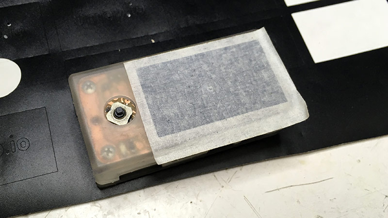
For the version 0.1.0 I made a basic two-part bottom-top enclosure without snap-fit joints to see what tolerances I would have to apply to the following designs. Below is an image of the case with electronics inside.
I was verry happy at this point and practically could not get my hands off the device, but after playing around with it, design flaws and possible improvements revealed themselves.
The most important improvement to be done was to make the hole for the 5-way button bigger. I made it 5mm in diameter, but it was blocking the axial movement of the switch. You could still press it down, but it was nearly impossible to use the X and Y axis push functionality.
I did not like the ISP header sticking out so much on the top surface that is supposed to be the face of the project. One of my design goals for the device is to keep it as simple as possible. Thus the ISP header was uglifying the face of the case. In the v0.2.0 of the PCB design I decided to move it to the bottom of the board, so I decided to improve the design of the case to reflect that.
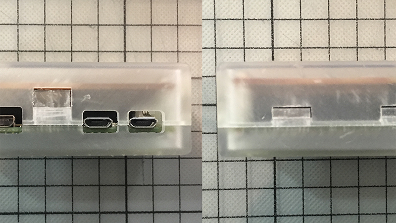
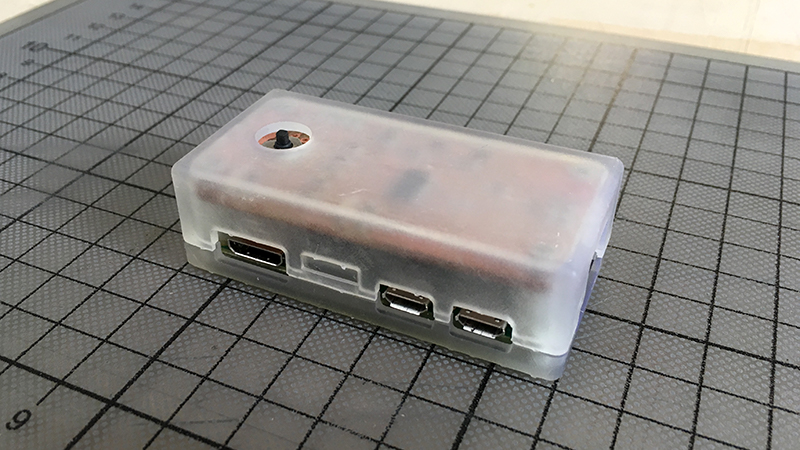
The third important thing to add was to add snap-fit joints, which as I expected took a bit more effort and multiple iterations. Together with that I decided to reduce the thickness of the case from 3mm to 2mm to reduce its bulkiness. Below you can see an image of the version 0.2.0.
As you an see in the image, the hole for the 5-way switch is shifted down a bit. This would be my first design fix. Another one is on the back side of the case. I misplaced the opening for the ISP connector.
Otherwise the snap-fit joints were fit. I made a longer version and a shorter version to see how well they snap. Below is an image of the joints. The one to the left is the longer version (snapping not so well) and the one to the right is the shorter version (snaps well).
It was clear that I have to make another print to fix the ISP opening, move the hole for the switch and improve on snap-fits. Unfortunately I did not check the resin tank before starting the print and a corner of my case did not get printed because of laser light being blocked by a piece of solidified resin stuck to the bottom of the tank. Otherwise it snapped well and felt good in my hand. Below is a photo of it (v0.2.1).
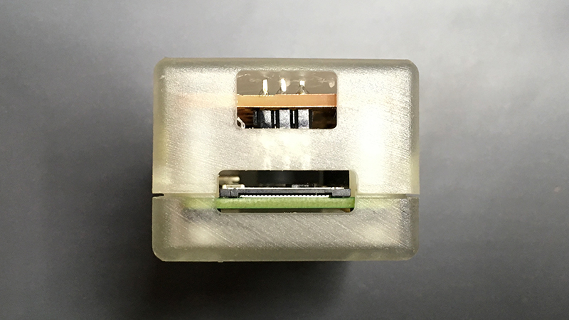
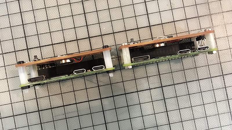
So I had to make another iteration. I noticed that the circular opening for the switch is still not completely in place. I was also hunting down proper spacers to put between the Raspberry Pi and the uMap board. I reduced the height of the electronics part by 4mm and had to reflect that in my design. Below is an image showing old vs new spacers.
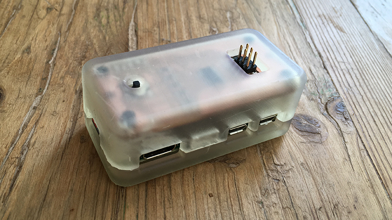
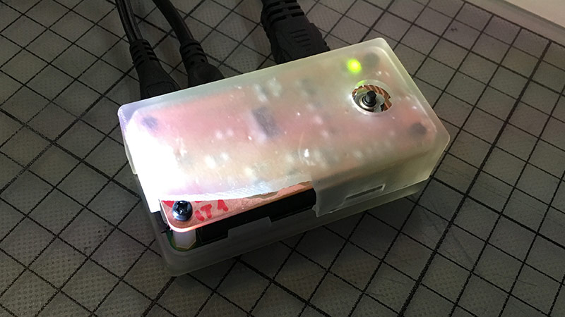
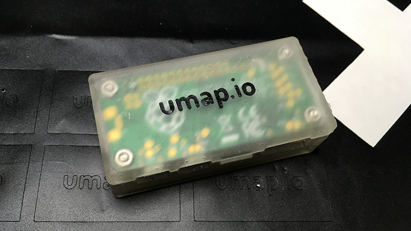
I adjusted the design and printed a new version of the case. For the last iteration (v0.2.2) I adjusted the joystick opening and the interior of the housing to match the new spacers (that glow in the dark by the way). Below you can see an image with housing v0.2.2.
Vinyl Cutting
I had to use a bit of content on the case itself. It is always nice to have some basic information about it there. Would it be the name of the product or a website address (or both in one). I wanted to add the website address of my final project there.
You can read more about vinyl cutting in my Computer-Controlled Cutting week, but the most important thing is that one has to save the file in Adobe Illustrator 8 file format. Import it into the CutStudio software and set up the vinylcutter.
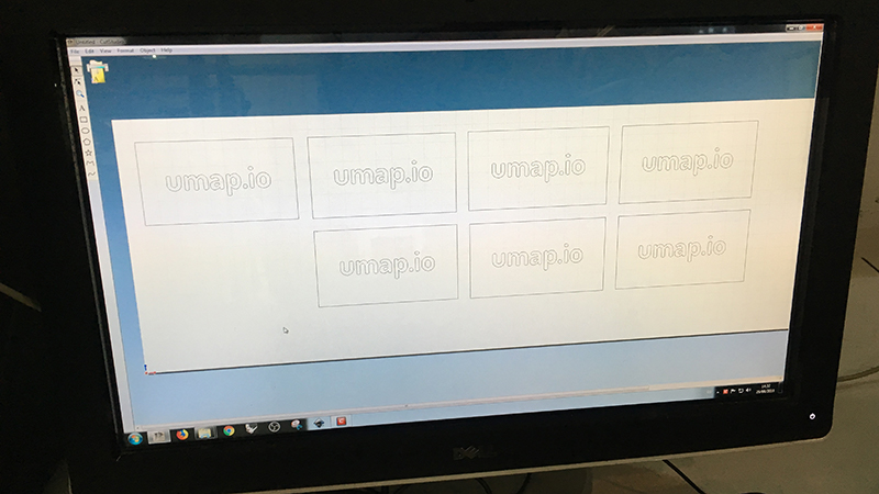
Do a test and cut the design.
Use a transfer tape to pick up the sticker from the sheet.
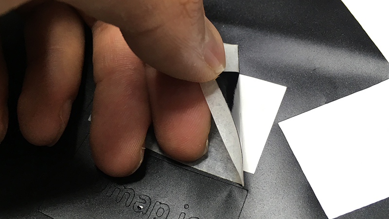
Position the sticker onto the surface.
Remove the transfer also picking up the parts you do not need. Do it gently by using a scalpel or a pair of tweezers.
Looks nice, but I realized that the glue is not strong enough and the surface is not adhesive enough. It would be best to laser-engrave it.
Software
I mentioned the fresh ideas before. One of them is to turn the Raspberry Pi into a WiFi access point and host a web application that would allow one to use the web browser to do projection mapping with the device. The device would then react in sync with what is happening in the web browser.
During the Interface and Application Programming week I was developing a web interface that would use WebSockets to communicate with the projection mapping application running on the Raspberry Pi.
I used threejs for the web interface and ofxLibwebsockets for WebSockets functionality in my openFrameworks projection mapping application. ofxLibsockets had a problem with hosting larger files from the Raspberry Pi, I used the SimpleHTTPServer that comes with python to host the HTML, CSS and JS files of the web interface. You can get more details in the page of the Interface and Application Programming week.
I also made available the uMap Web Interface Demo on Fab Academy GitLab. It should work on all major browsers that support HTML5, CSS and JavaScript, WebGL being a plus. If you can not access it or the repository is not there anymore for whatever evil reason, below you can see a screenshot of it.
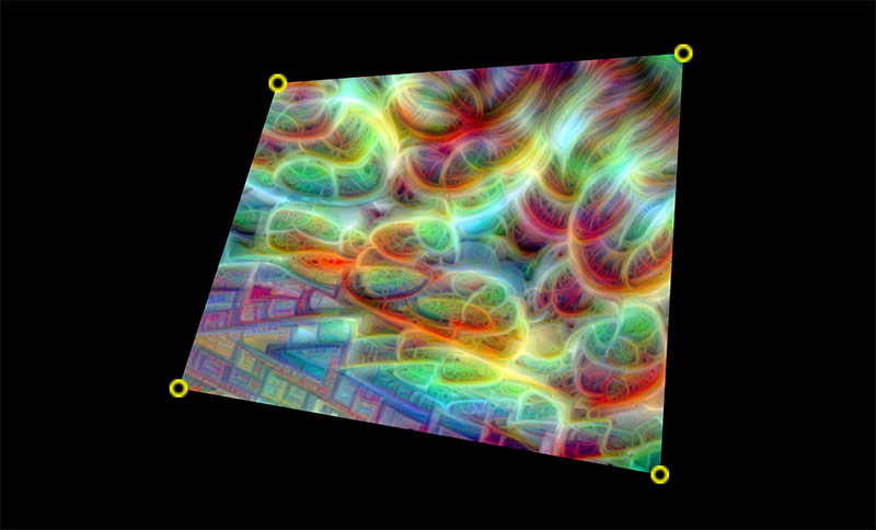
In the future versions the interface will become more complex as the idea is to do very basic adjustments with the joystick button on the uMap box and use the web interface to set up the composition. It will include the option to add new surfaces, do mesh warping, rotation as well as upload new textures and configure various properties of uMap.
Operation
uMap is supposed to be easy to use and even a person not familiar with projection mapping should be able to have fun with working with the joystick interface. I will describe a possible scenario from the perspective of a gallerist who has to take care of a piece that an artist has just set up using uMap.
First of all it has to be connected to a projector by using a HDMI cable. Then it has to be powered by using a 5V 2A power supply which is a general recommendation for Raspberry Pi minicomputers. It boots up into presentation mode, which means it displays the last saved projection mapping composition.
A few days after the artist set her piece up, the gallerist notices that the projected image is a bit off where it should be. The gallerist approaches the box and starts pressing the joystick button. After each press the gallerist feels a slight vibration coming from the box which is caused by the integrated vibration motor.
The image is a bit to the left from where is should be, this is why the joystick has to be pressed to the right. The projected image moves to the right and matches the object.
Except there is one corner that could be adjusted better. The gallerist presses the joystick button in order to select the corner of the surface to be adjusted. Each button press selects the next corner clockwise. Once the corner is selected, the gallerist can use the directional joystick button features to adjust the position of the selected corner. Now the projected image matches the object perfectly.
Bill of Materials (BOM)
I made the bill of materials as a part of the Applications and Implications week. Click on the BOM link to download it.
Files
Below is a list of files that are the final versions as far as for the Fab Academy course. Some (if not all) of these will be later released on GitHub or similar platform as a part of the uMap project.
- Eagle schematic and board files
- Exported PNG traces for Mods
- Arduino code for the Raspberry Pi HAT PCB
- Fusion 360 project file of the housing
- 3D-printable STL files of the housing
- Sticker design for vinylcutting
- openFrameworks app source code (including web interface in
bin/data) - Bill of Materials
Conclusions
I am generally sattisfied about the outcome of my final project. I wanted to get it to a state which could initiate preparations for a crowdfunding part and it seems that I have gathered enough data to start seriously thing about that.
The main flaw in its execution was that I started to work on it a bit too late. During the first weeks I was testing the ground with half-baked tests, but I should have done straight into the development. I would have managed to get much farther if I would focus more on the final project during every single week from the very beginning.
A reason for that (thus a critique for the way Fab Academy runs) is that there is a bit too much confusion caused by non-speciffic information about when the work on the final project should be done. From my perspective now one should focus on it from the very beginning as two weeks at the end are obviously not enough for it. One can argue that the time of the last assignment weeks can be shared with it; I would say NO, they can not.
I would also throw in more topical workshops (areound 2 hours in duration) for explaining critical concepts for each week. The goal for those workshops would be also show a realistic way to finish the assignment. Here I am talking about concepts such as MISO and MOSI (ask around and you will find a few who know that it actually means Master In Slave Out and Master Out Slave In), bit shifting, a decent introduction oto HTML (for kids that have no experience with it) and less nerdy guide to Git and GitLab.
To end on a positive note, I enjoyed the experience, got new friends, started to feel at home in Barcelona, learned to use new machinery, widened my perspective in terms of many things. My personal goal in terms of Fab Academy was to learn more about electronics. So far I have used only through-hole components and did not have experience with making custom PCB’s. It was exciting to iterate on the design and production of the double-sided boards for my final project, I made 6 of them in total.
Injection molding would be a nice addition (or continuation) for the project of mine and this is what I start with the wildcard week and would like to explore further after the graduation.
License
Everything related to my Fab Academy course and the final project is licensed under the Attribution-NonCommercial 4.0 International license which means that you are free to:
- Share — copy and redistribute the material in any medium or format
- Adapt — remix, transform, and build upon the material
Under the following terms:
- Attribution — You must give appropriate credit, provide a link to the license, and indicate if changes were made. You may do so in any reasonable manner, but not in any way that suggests the licensor endorses you or your use.
- NonCommercial — You may not use the material for commercial purposes.
- No additional restrictions — You may not apply legal terms or technological measures that legally restrict others from doing anything the license permits.
And usually with CC licenses there is a small logo image included which summarizes the licensing information above.
