
Week 17
For the wildcard week I chose to experiment with injection molding for my final project. In order to move my 3D electronics housing design into the injection molding phase, I had to do multiple design and 3D printing iterations.
Once I felt that my 3D printed case houses the electronics well and feels good in one’s hand, I was ready to create a design for the molds in Fusion 360. You can read more about the 3D printing process in the 3D printing week.
I plan to use the injection molding machines developed by the Precious Plastic team. It would be interesting to be able to make injection molded cases for my final uMap project. It would add a conceptual step-up with the fact that recycled plastics would be used for creating parts of the final product.
During the Maker Faire Barcelona I met people from Esferica and they made me feel very sceptical and curious about the process of creating a mold. They created two aluminium molds for their plastic sunglases and spend 2000 EUR in doing so. I felt the challenge of proving that one can avoid that 2000 EUR part.
The Plan
My plan is as follows. Take the design of the housing that I used for the 3D printed version of the final project. Next translate it into a negative model for the mold. I would need to measure and design the connector of the injector to be able to fit the mold perfectly.
I would then use Roland SRM-20 milling machine to mill MDF. I would use skills learned in the Molding and Casting week to create the milling passes for the machine. Since it would be a double-sided mold to be fit together nicely, I would do a serious surfacing pass with a flat tool to make sure that both sides snap together well.
I foresee problems with the snap-fit parts since they contain geometry that would be impossible to mill with a straight tool. I might get results with a ball-nose or disc end mill if I manage to find them. Most likely I will avoid this step to get the first injection molding cycle done as fast as possible.
I believe that mold prototyping with MDF could be a good way for affordable iteration on molds for injection. Once a successful mold would be created, one could adjust the process to mill in aluminium instead of MDF, thus also having less probability to fail.
Research
In order to create the mold, I had to take a look at the injection molding machine at the Fab Lab Barcelona. I found it with a note next to it. The most important thing was that it exists and it looks real.
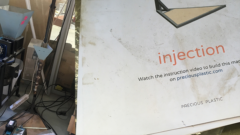
The note next to it hinted me to take a closer look at the documentation of the Precious Plastic Injection machine. First step for me was to watch the video about building the Injection machine in order to understand how it works. Apparently it is not too difficult, all you need are some standard metal tubes and profiles as well as a metal working workshop.
Next step was to find more information about how to create a mold for the machine. There I found it on the YouTube channel of Dave Hakkens, a video about how to make a CNC mold for the Precious Plastic machine. Watch the video below.
First thing I noticed was that the 3D model of the iPhone case that was being designed has the thickness of 2.5mm. The latest version of my final project housing has thickness of 2mm. I am not worried though, I can change the thickness parameter in Fusion 360 and the design of the housing will be recalculated automatically.
In short, below is a list of facts to keep in mind while designing the mold.
- Keep the thickness more than
2.5mm. - Design filets for cheaper and faster CNC milling.
- Add a male/female groove to snap both mold parts together.
- Place mounting holes asymmetrically for proper alignment.
- For housing parts it is a good idea to make a 3-part mold.
- Injection point or sprue should have a draft angle which means it should be narrower at the top and wider at the inside. The conical shape helps to remove the part from the mold.
- One can use Autodesk MoldFlow software to analyze how the plastic is going to flow through the mold.
Some other terms to keep in mind.
Sprue: opening where plastic enters the mold.
Runner: channel for molten plastic to flow.
Gate: opening where molten plastic enters the actual object part of the mold.
Parting line: plane that separates two parts of the mold.
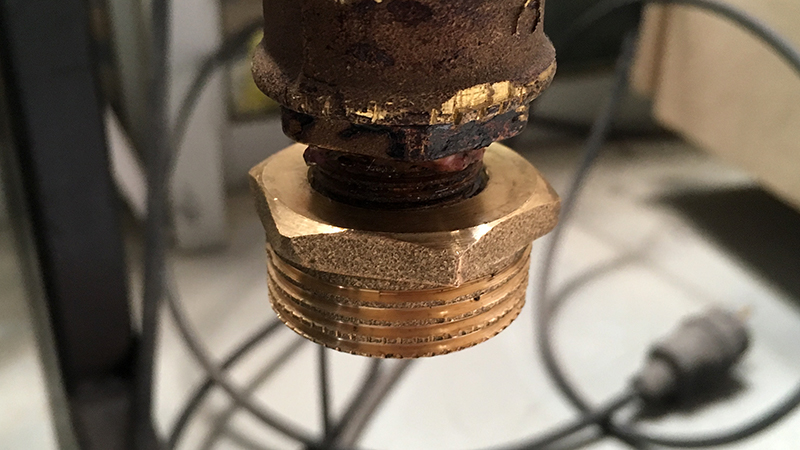
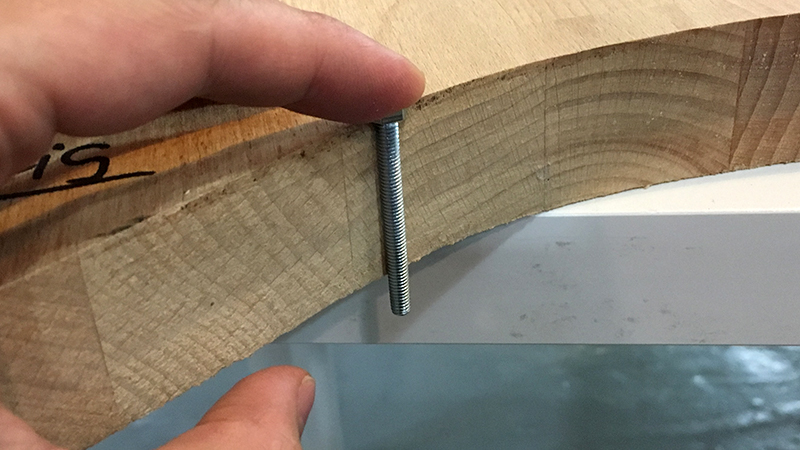
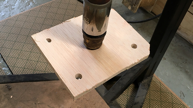
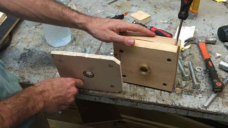
All in all it seems like a longer process, but to get started on my side, I wanted to figure out the simplest possible way to attach the ready mold to the Precious Plastic machine. You can see a photo of its nozzle below.
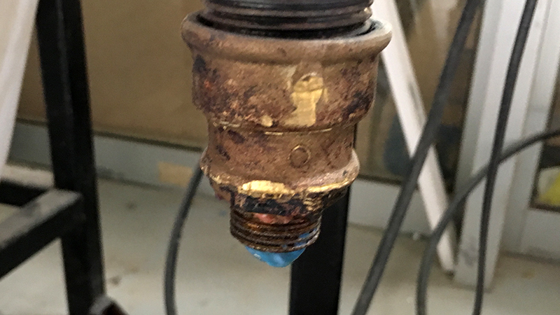
I had to get precise measurements of it. As I want to use MDF for my first experimental mold, it is soft enough for last-minute threading with the nozzle itself. What I had in mind is to measure the diameter of the non-threaded part of the nozzle and mill a hole in the top side of the mold.
The diameter of the nozzle is
20mm. I will make it1mmless to pressure-fit the MDF mold to the thread of the nozzle.
I also found bits and bolts to tighten both parts of the mold together. Below you can see an image of the bits and bolts I found.
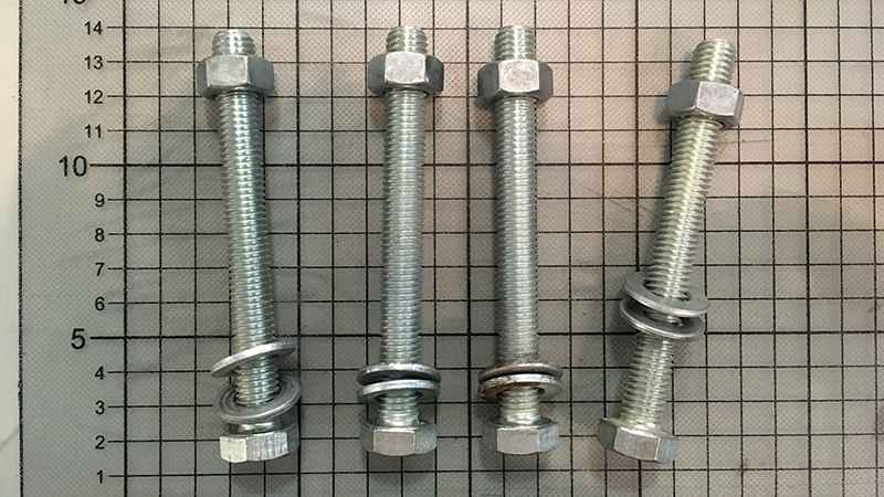
The bolts are 110mm long and the diameter is 10mm. As you can see I also found some washers to protect and support the top and bottom surfaces of the mold.
I met Ingi before leaving Fab Lab and asked for a few recommendations regarding the injector as he has been around Fab Lab Barcelona for long enough to have seen someone using it.
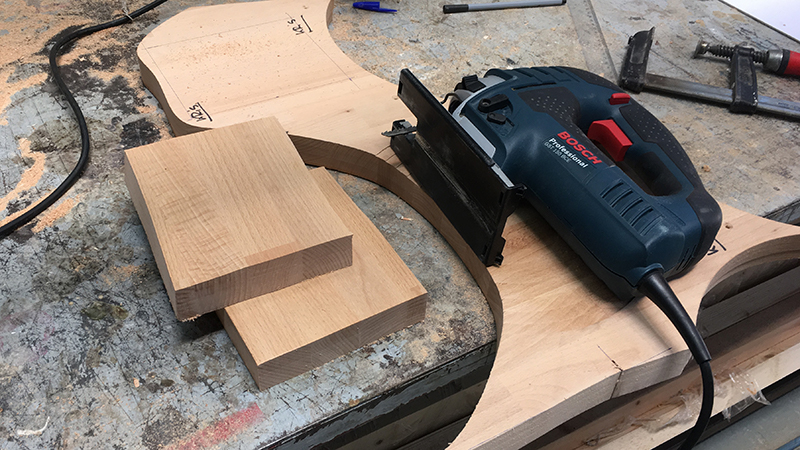
I told him about my idea to make the mold out of MDF. Ingi suggested to try high density wood instead. I found a piece in the scrap box.
Then I had a long night thinking what would be the best way to connect the mold to the injector nozzle. My initial thought was to use nothing but a hole in the wooden mold and pressure-fit it to the nozzle.
I remembered the scene from the mold design video by Precious Plastic where they actually connected the mold to the injector and were both hanging on the handle to press the plastic into the mold.
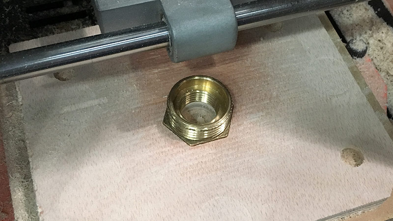
Therefore I understood that pressure-fit is not going to be enough and I went to Servei Estacio to look for some threaded plumbing parts. I found what I was looking for.
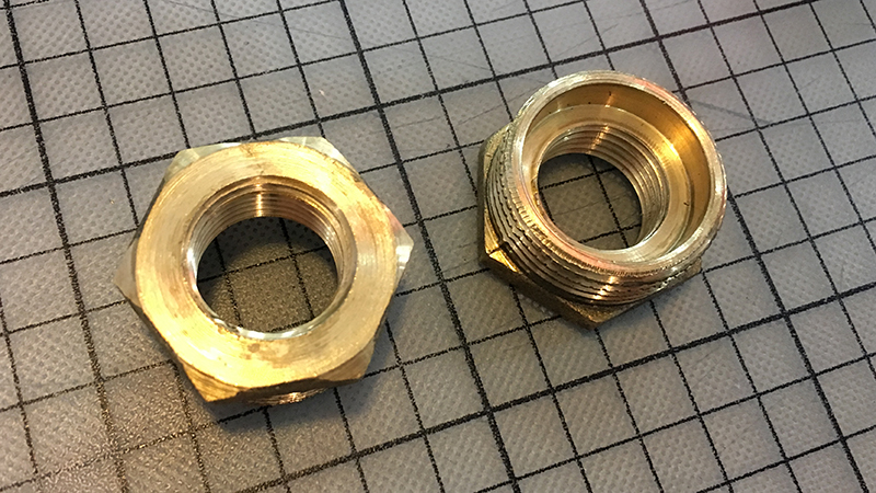
I also made a test to check if the thread fits onto the injector male nozzle. It did.
At this point I had all the parts to start design the mold around them.
Design
I was ready to follow the advice of the Precious Plastic YouTube tutorial and was up to make a 3-part mold in Fusion 360. First step was to change the thickness of my uMap case to 2.5mm as it is the least recommended thickness for the Precious Plastic Injector machine.
Then I made a new project file for the mold. First thing after importing the housing design was to set the source material (high-density wood scrap) thickness which is 32.5mm. Then some other measurements as the lenght and diameter of the screws as well as offset that I want to have around the part in the mold.
Then I started to model the base of the mold that would include cavities for connecting the mold to the injector nozzle and holes for the fastener bolts.
I tried to cut by using the uMap housing, but quickly realised that it might be too detailed for the very first try. I went on to simplify. I reduced the design to not contain any holes on the sides and no lips for fitting both parts of the final box together. That would be just enough for the first try.
I imported the reduced design into the mold design and cut the top and bottom parts of the mold by using the housing design as the tool. To do that you can use the Modify / Combine tool in Fusion 360. Select the target body or component, then the tool to be used. You can also choose what operation to perform with the tool. Would it be join or cut? In our case it is cut. Below you can see a video of the result.
Looks like a simple task to mill this, but I foresee problems with the detail level of the outcome. But identifying problems and limitations is my main purpose of the task.
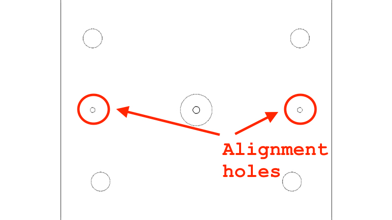
It also looks that I will have to mill from both sides of the top mold. The most important part is the cavity for the injected object, but on the other side there is the connector for the injector nozzle.
Which means I have to add alignment holes that will span the longest midline of the design. I added two 3.1mm alignment holes that cut through all parts of the mold. I chose this diameter as I used the same diameter tools for the production of my double-sided PCB. See the following image.
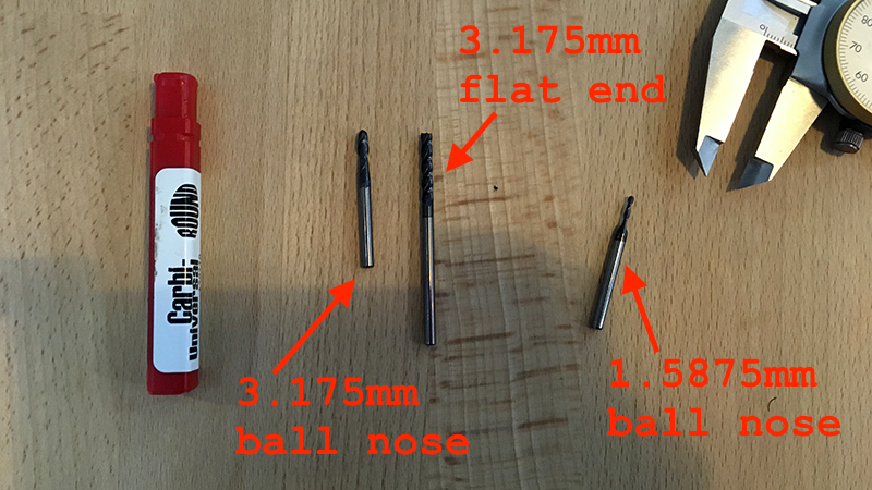
I started to become worried about the milling process, whether the tools are going to cut it. At the lab I was able to find the following tools for Roland SRM-20.
1.5875mm (1/16)ball nose (2FL)3.175mm (1/8)flat end (2FL)3.175mm (1/8)ball nose (2FL)
The maximum cut depth for the bottom part of the mold is 14mm. The smallest tool I found can cut only half of that. There were two possible paths at this point.
- Simplify the design even more.
- Increase complexity of the mold design.
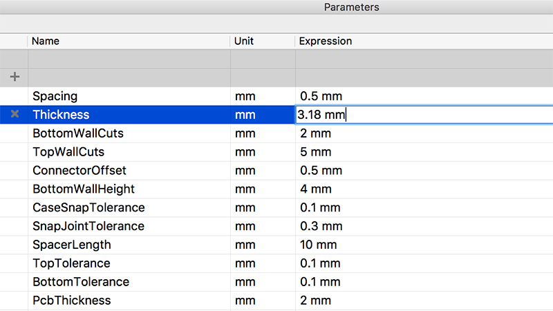
Since this was supposed to be an experiment, I decided to go with the first one which means I would increase the thickness of the object to 3.175mm in order to match the longer tools at hand.
The 3.175mm ball nose tool was just long enough for my purpose, even though I could access a longer version of it. However, I went on to increase the thickness of my object. I increased the thickness of the object to 3.18mm and imported it into the mold design again.
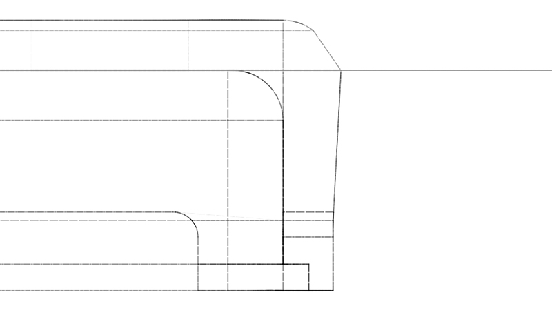
Something had to be done in order to make it easier to remove the object from the mold after. First thing to be done was to add a draft angle for the walls to be molded. The easiest way to do that was to select the connecting edges of the object on both parts of the mold and offset them a bit.
Leave a draft angle of
5degto be able to get a part out in case the plastic shrinks against the mold.
The following image shows how it looked like after using the chamfer function. It is not perfect, but hopefully will work to an extent.
Another thing that I wanted to add is an ejector hole. For that I decided to use a bolt and design the hexagonal top to fit the surface of the interior. During injection phase the bolt would remain inside. By hitting it on the other side after injection, one could remove the part much more easily.
The dimensions of the bolt found are as follows.
- Diameter:
4mm - Length (without the hexagonal head):
40mm - Hex head diameter:
7mm - Hex head thickness:
3mm
Below is where you can see it integrated into the mold design. The Fusion360 render engine also did a good job to project my expectations.
For the rather detailed hexagonal head of the bolt I might use a smaller tool, such as the 0.8mm (1/32) flat end one. For that to work as expected, I had to add 0.8mm filets on the sharp hexagonal edges.
At this point I was able to start to lay out the parts for milling. I am going to use methods and software described in the Molding and Casting week.
Milling
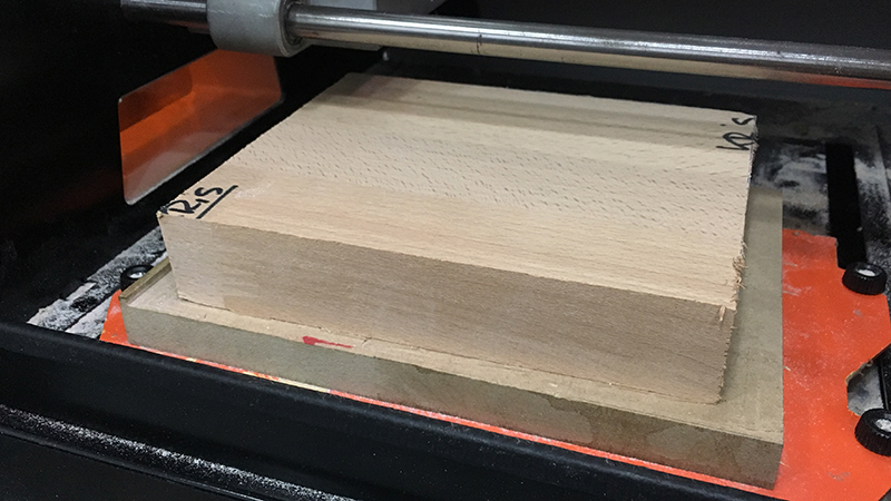
Once the design in Fusion 360 is done, one can export .stl files for importing them into another software. I took advantage of the knowledge that I gathered during the molding and casting week and went on to use the Modella Player 4 software to create strategies for the Roland SRM-20 machine. For that I needed to remind myself the dimensions of the material I will be using.
- Width:
170mm - Height:
140mm - Thickness:
32.5mm
I also had to cut the material pieces out from the leftover material that I found at the lab.
Material Settings
Then I created strategies in the Modela Player 4 software that was available on one of our lab computers. After opening the .stl file of one of my designs, the first thing is to set the material with the Set / Material menu command.
I had to rotate the model 90deg around the Z axis to make the horizontal edge longer as the vertical one since the bed of the Roland SRM-20 machine is set up that way.
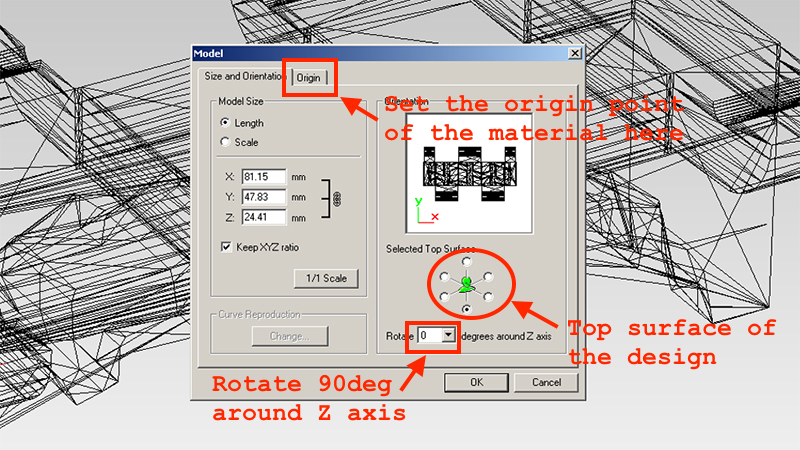
If your model is double-sided, you can select which of the surface is the top one. Select the origin point of your material as well.
Modela Player 4 mirrors the bottom surface if you chose it to be on top.
The limitation is that you have to do this for every part of the design separately and from scratch.
Tool Settings
I had the 3.175 tool set up for milling, one thing I had to adjust was the material settings for it. It was configured to cut modelling wax, I was going to cut Wood (Hard).
To adust the tool settings, one can use the Options / Add/Remove Tool menu option. It will open a dialog window with all the tools installed. I selected the 3.175 tool and clicked on the Cutting Parameters button to open the cutting parameters dialog for the tool.
I had to chose Wood (Hard) material from the Material drop-down menu. It would display the default values for cutting one’s desired material. One can do adjustments if the wood is harder or softer than the projected default.
The Set Parameters button has to be pressed to add the material cutting parameters to the tool. Now the tool can be used to cut your desired material.
Toolpath Generation
The design of my mold looks like a sandwitch and the middle part of it is going to be a double-sided part. For that to work, alignment tabs have to be placed and for that we need a drilling strategy.
In Modella Player 4 a separate tool has to be set up for drilling. First I tried to use the same 3.175mm flat-end tool that I cnfigured for hard wood, but Player 4 did not allow me to use it.
I went to the Add/Remove Tool dialog once more to add a tool for drilling. I copied the 3.175mm tool, changed its type to Drill and added hard wood as the main material for it to cut.
To create a new toolpath (or Process) in Modella Player 4, one has to click on the New Process button on the top right part of the window. Player 4 will ask you to specify the type of operation you want to create. I selected Drilling which is the 4th entry in the menu.
You will be prompted to select the cutting surface, leave the default value (Top [+Z]) there. Click Next. Next you will be prompted to select the tool you wish to use for milling. I selected the 3.175mm Drill tool from the menu. Clicked Next once more.
At this point you should be able to see a menu where you can select the cutting area and specify drill points. For each drill point you can specify coordinates and depth. I went with 5.5mm for each drilling point since my alignment tools are 10mm long.
I would reuse the drilling strategy for my double-sided parts (which is only the middle part of the design), however I tried it out with the bottom part of the design first to check for potential adjustments.
Creating Roughing and Finishing processes was the next thing to do. I chose the 3.175mm flat-end tool for the purpose. You can read more about setting up and using this tool in my Molding and Casting documentation page.
Cutting
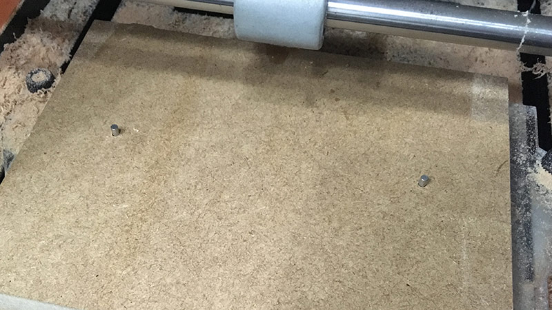
One problem I faced was the way to attach the material to the bed of the machine. There was no decent double-sided tape around, so I used a thinner one that was at hand.
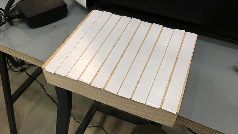
I started with the bottom part strategy also to test the drilling strategy first before applying it to the double-sided part. For the drilling part I realized that I forgot to add depth for the second hole in the strategy. I fixed that in Modella Player 4 right away for the next cut.
The roughing part went slow but good. I wanted to finish cutting the mold in one day and wanted to skip the finishing part at first, but the closer the day went to an end (the lab was closing at 6pm) the more I understood it is not going to happen. So I ran the finishing strategy and I believe the material has moved and at some point the milling went wrong and I ended up with the machine stopping and the bottom part of the mold damaged.
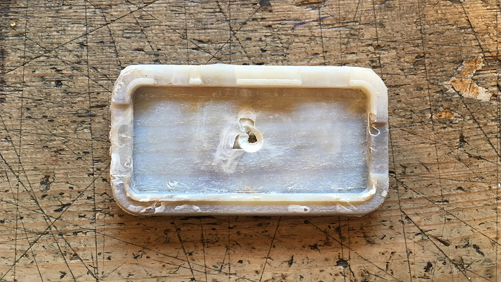
I found a thinner material for the top part of the mold that I designed for the purpose of pressing the nozzle bit in place. I had to repeat the loop of editing the design, setting the thickness to 12mm, exporting it, and generating roughing and finishing strategies for it.
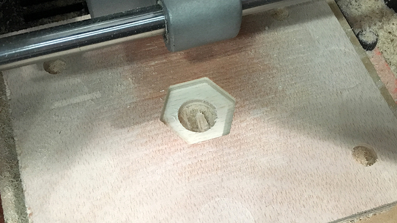
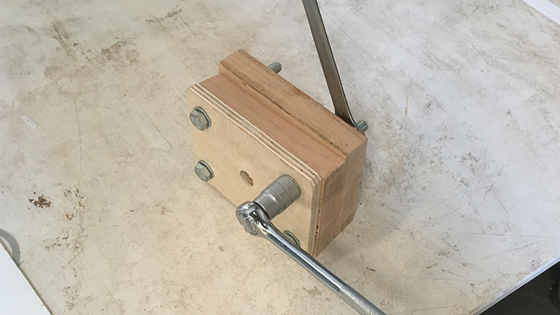
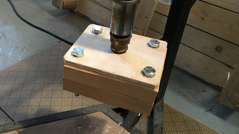
As you can see the nozzle bit fit perfectly into the mold. I tried to attach it with the top part to the Precious Plastic injector right away to see if I can celebrate an intermediate success this day. I was able to do so.
I am not sure if this will be enough to withstand the pressure, but this is why I am doing the whole thing this week, to test if there is a cheaper way to make a mold for injection molding.
At this point I had to leave the lab and I realized that I need one or two more days to finish it. It was a bit of a rush, but I learned a few things on the way.
Housing Redesign
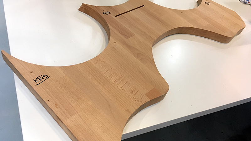
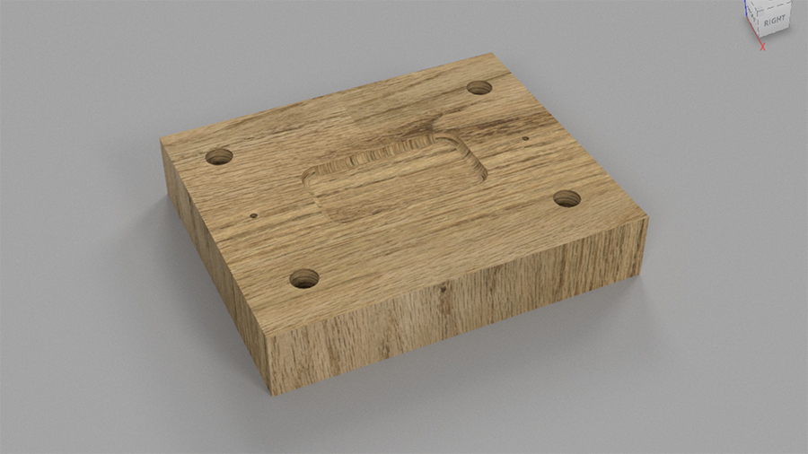
After the fail there were two days without the possibility to mill again. It was enough time to redesign the uMap case so it takes into account some of the most important injection molding and milling limitations. Below you can see the redesigned case.
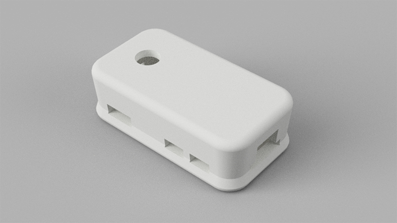
As you can see it is slightly inset towards the middle. This is because I took into account the draft angle of 5deg to make it easier to remove the object from the mold. In order to achieve this I learnt the sweep function in Fusion 360. Watch the video below to see how I made the walls with the sweep function.
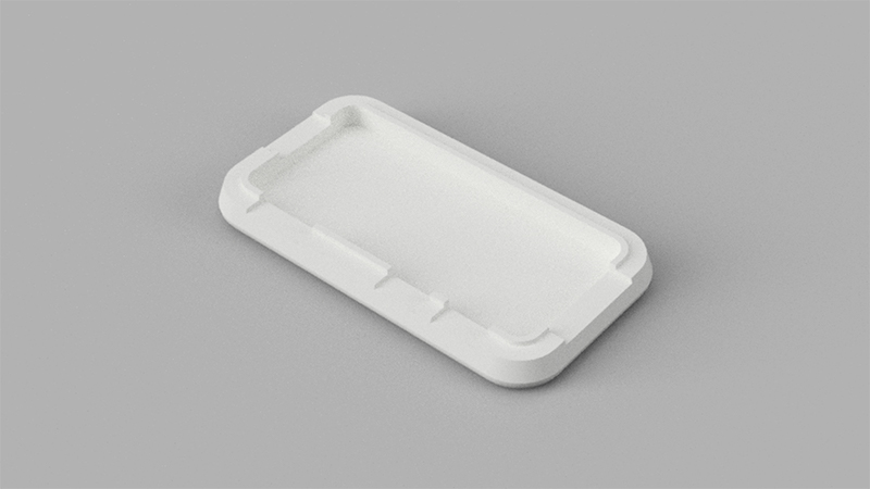
Using this method as a base I designed a new housing where the uMap circuit was sitting in nicely. I decided to first try to prepare the bottom part of the housing since I made it he most detailed.
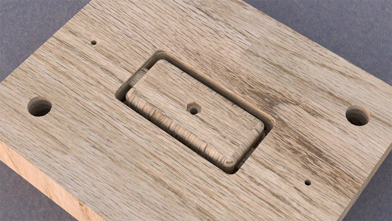
Can the final object have details that are as small as one millimeter?
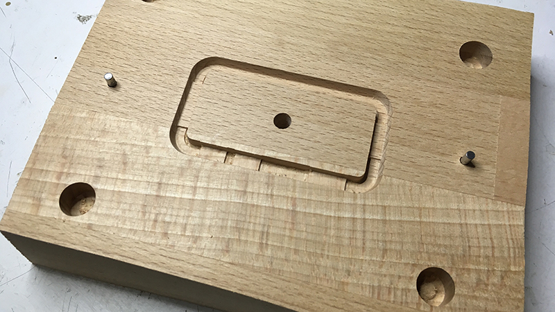
below you can see an image of the bottom part of the case. You might notice the thin groove along the inner edge of the wall.
Mold Redesign
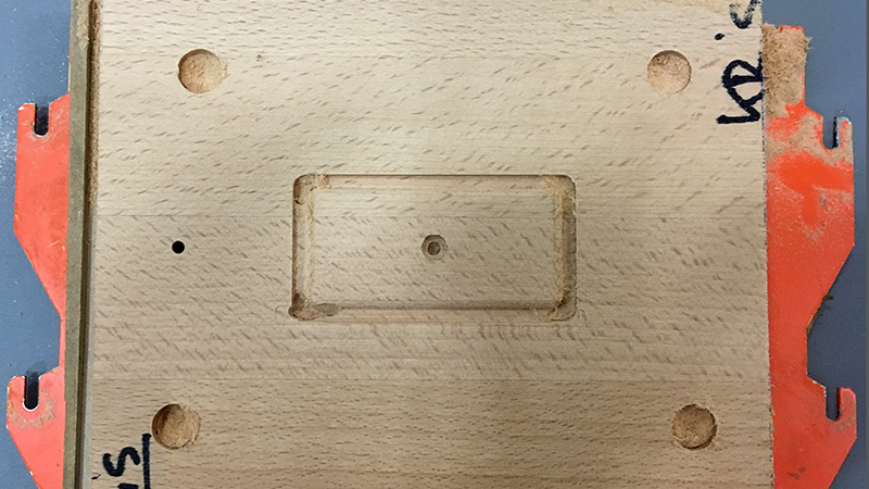
I did not redesign the mold from scratch. I could take the intermediate pieces that had the alignment for the bolts and thread. All I had to do was to position the bottom part of the housing in a way that I do not have to mill any extra surface material away which would be the case if I would include a groove to block molten plastic to escape the mold.
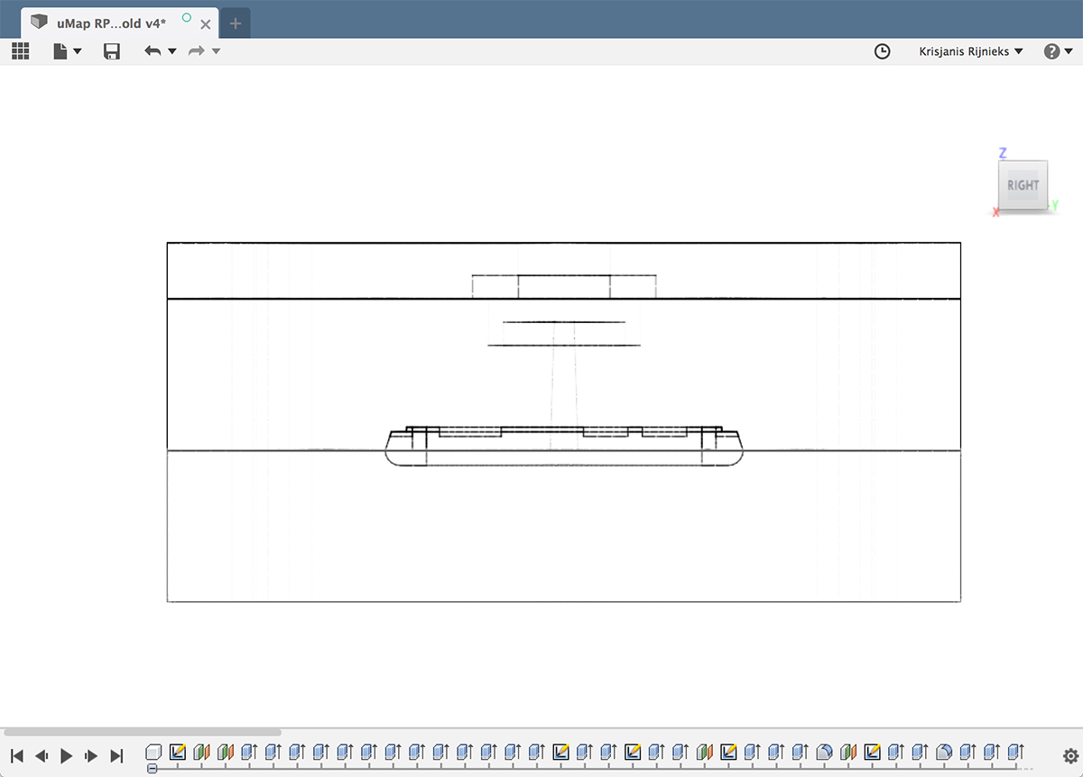
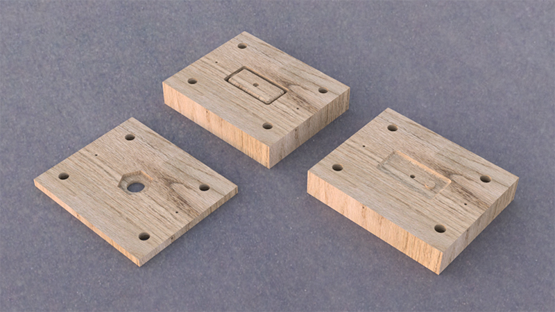
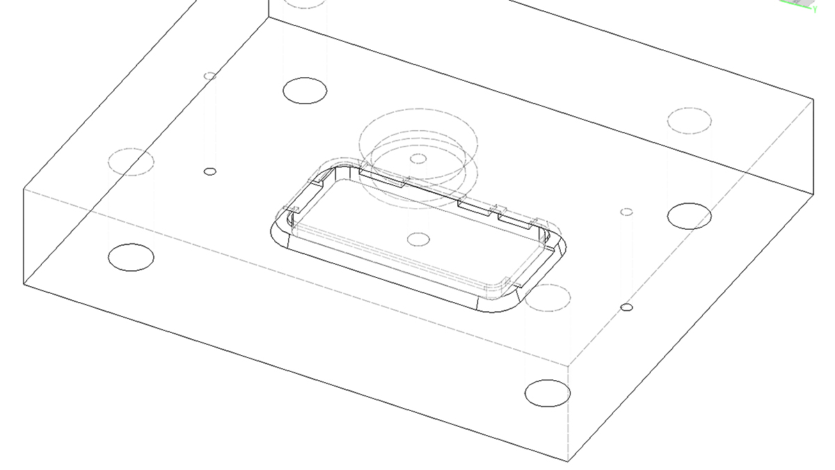
I used the Modify / Combine / Cut operation in Fusion 360 to create negatives of the model in the mold top and bottom bodies. I ended up with having a relatevely easy to mill bottom part and a bit more complicated top part where I would need to use double-sided milling to get things done right. You can see an image of the bottom part of the mold.
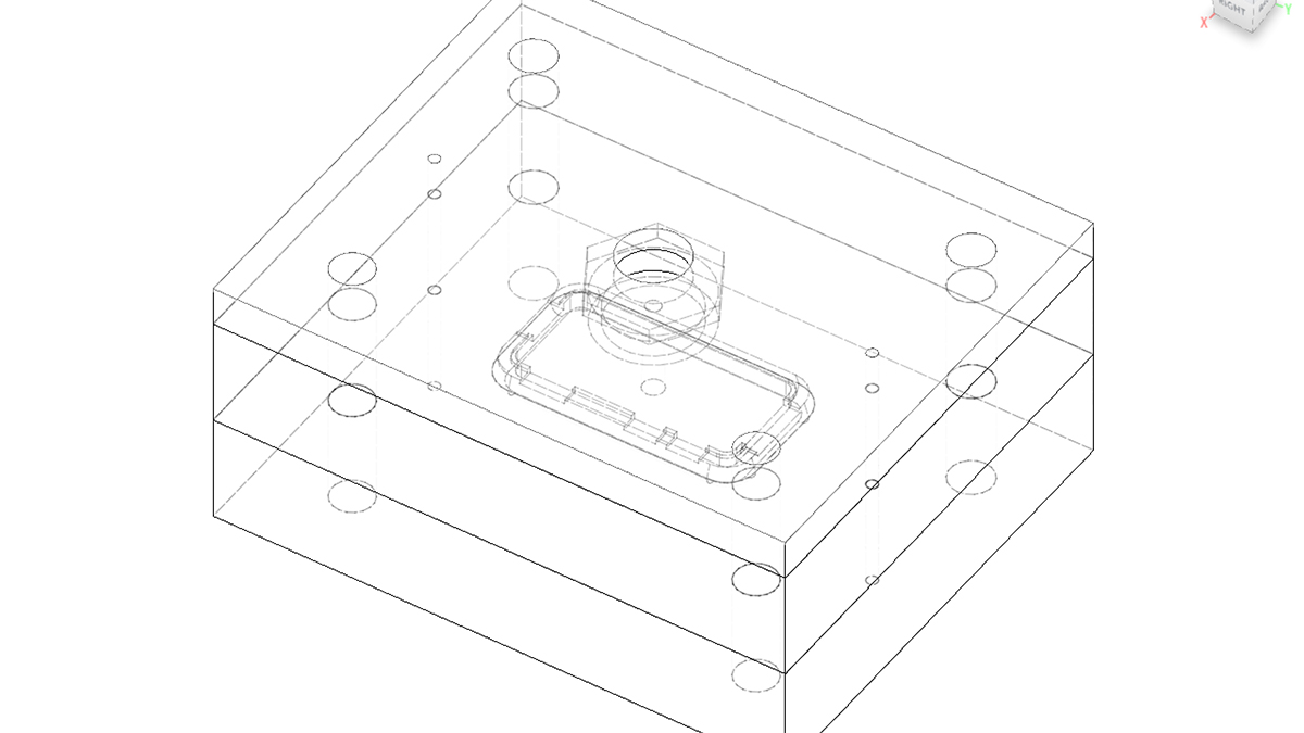
The top part of the mold was a interesting challenge for me. After spending some time for thought I realised that it would be much nicer if I would hide the sprue connection inside the housing. It would potentially lead to problems cutting the plastic coming from the sprue, but if things go well, would lead to much nicer finishing.
Then there is the very top part which would clamp the injector nozzle thread and hold it down once exposed to pressure. The thread would be in-between the top and clamp parts of the mold. The thread is also the main reason why I had to design the top part to be milled using the double-sided approach. Below you can see all parts of the mold connected.
Milling the New Mold
I tried to use Fusion 360 to create toolpaths for milling first. It went well until I realized that the Roland post processor for Fusion 360 does not support SRM-20. Apart from that there were a few other issues that I could not solve as fast as I would want to, thus I went bac to generating milling strategies with the Modella Player software.
After a few times of using Modella Player, the way it is organised starts to make greater sense. For the mold I was going to mill, all four basic operations would be used.
- Surfacing
- Roughing
- Finishing
- Drilling
I used the surfacing strategy with 3.175mm flat endmill (I wish I would have had something thicker) for the connection between the top and bottom parts of the mill. The surface had to be as straight and smooth as possible to avoid molten plastic flowing outside.
The following are milling strategies that I used for the bottom part of the mold.
- Surfacing (
3.175mmflat endmill) - Roughing of the mold pocket (
3.175mmflat endmill) - Finishing of the mold pocket (
3.175mmball endmill) - Roughing of the clamp bolt holes (
3.175mmflat endmill) - Finishing of the clamp bold holes (
3.175mmflat endmill)
For the clamp part of the mold I flipped it upside down and used the following strategies.
- Roughting the hex pocket for injector nozzle connection (
3.175mmflat endmill) - Finishing the hex pocket for injector nozzle connection (
3.175mmflat endmill) - Roughing of the clamp bolt holes (
3.175mmflat endmill) - Finishing of the clamp bold holes (
3.175mmflat endmill)
The most complicated part was to create strategies for the top pocket with the 1mm details deep inside the mold. The following is what I used.
- Surfacing with
3.175mmflat endmill - Roughing with
3.175mmflat endmill - Finishing with
3.175mmball endmill - Finishing with
0.1588mmball endmill - Finishing with
0.79mmball endmill - Roughing of the clamp bolt holes (
3.175mmflat endmill) - Finishing of the clamp bold holes (
3.175mmflat endmill) - Drilling alignment holes with
3.175mmflat endmill
I did use the same drilling strategy for the alignment holes to drill into the sacrifying layer to be able to insert the alignment pins.
The following strategies were used for the clamping part of the mold. Here the 3.175mm endmills were too fat, thus I realized that I have two 3mm endmills that I always cary with me in the wallet.
- Roughing with
3mmflat endmill - Finishing with
3mmflat endmill - Roughing clamp screw holes with
3.175mmflat endmill - Finishing clamp screw holes with
3.175mmflat endmill
That’s it! All parts of the mold are ready.
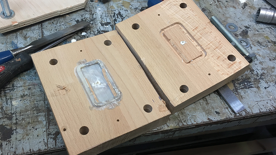
Below you can see an image of all parts milled just before putting them together to test the injection part.
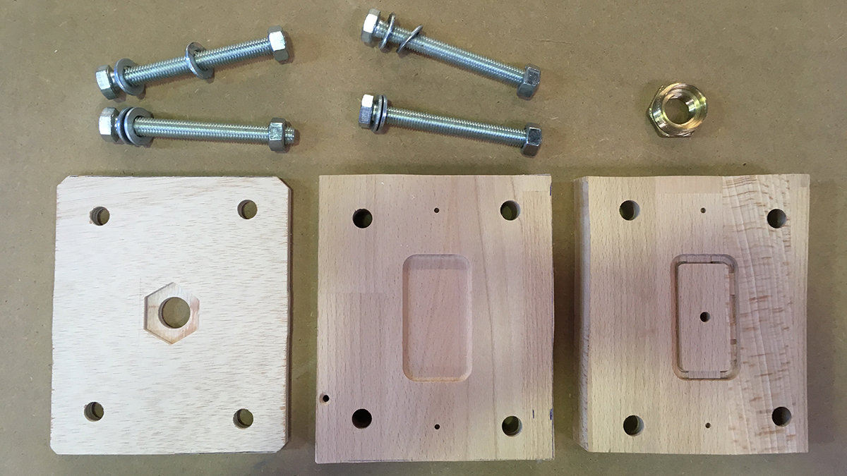
And one more image that illustrates the process of putting all the parts together.
Injection
Before doing the actual injection I wanted to test the machine itself. I got the concepts of how the Precious Plastic injector works from the YouTube video that you can find earlier in this page, but I had to touch it and try it out to fully understand and feel how it works.
There are two temperature controllers on the machine. One of them heats up the top part of the tube, another the bottom one. One has to set the temperature of the one closer to the nozzle higher than the ones on the top. I chose 210degC for the top ones and 220degC for the one on the bottom.
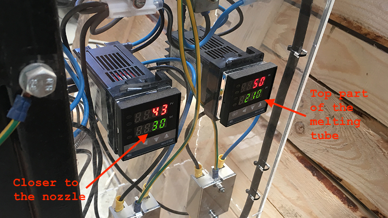
The top (red) number of the temperature controllers indicate the actual temperature of the tube and the bottom one (green) indicates the target temperature in degrees Celsius.
I gathered some PLA scrap at the 3D printing room of our lab and tried to quick-shred it enough so it would fit in the pellet syphon of the injector.
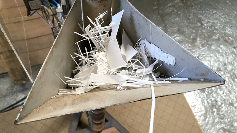
I had to iterate a few times to get it right, but I could get all the shredded PLA into the tube and start heating it up. After 5 minutes of waiting it smelled like the plastic is molten enough to try pushing it through the nozzle.
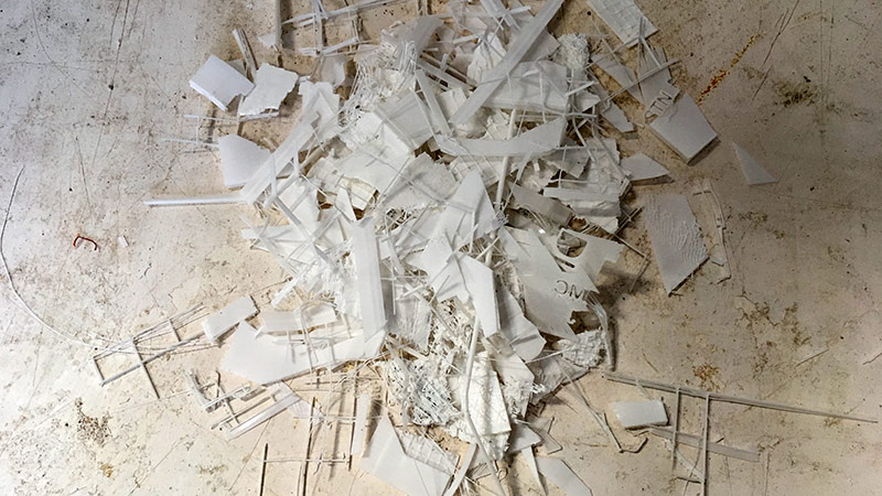
And as you can see it worked out well and created an alien-creature-looking object on the base of the injector machine.
After making sure that the plastic is melting and it is possible to press it out through the nozzle, I was ready to connect the mold to the nozzle.
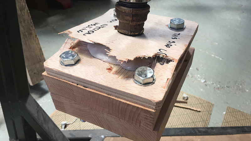
I made a little event out of the injection process. Many fellow Fab Academy students were interested into it and I was able to gather a group of people around me to help execute and document the process. It did fail the first time as you can see in the video below.
The following is a closeup of what actually happened.
Luckily I had a replacement clamp part and I could use it to repair the mold and try again. The second attempt worked fine and I was able to open the mold to see what the result looks like after cooling the mold down a bit.
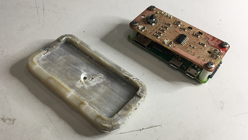
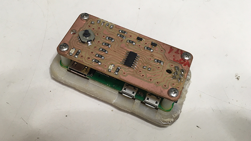
And finally it was possible to see that the injection went well and we got an actual plastic part waiting for us inside the mold!
Unfortunately the mold did not survive, but it was expected since that was the very first attempt to create a mold like this for me and people at the lab. All in all I register this experience as a success. Below you can see several hero shots of the final result.
We celebrated the success with a sip of champagne at the lab. Thanks everyone for joining the experience.
Conclusions
Injection molding is complex only because there are a lot of variables to consider. However, once the variables are known and converted into constraints it actually makes it easier to make design decisions.
For a designer who knows that her object will be injection-molded it is better to know the limitations as it will affect the complexity and thus the cost of the production process. Here is a list of things one should consider when designing a mold.
- Consider draft angle of
5deg. 2.5mmminimal thickness.- Avoid straight walls.
- Add fillets everywhere.
- Prefer round shapes.
Generally the idea is to keep things as simple as possible. For snap-fits to work, one has to carefuly choose the right type of them to make them work. Sometimes choosing the right tolerance between positives and negatives could be the best way to do.
As for the result, it was the first iteration. I was hoping for more, but expecting less and the final result lands in-between the two poles.
It is possible to create details
1mmin size with the Precious Plastic injector.
I left a straight wall on the inside of the cavity and it seems that it was the main reason why the mold got destroyed. The plastic adhered to the straight wall and took the wood with it while removing the object.
Ejector pins seem a good idea to employ in the future designs. Another thing to keep in mind is to add pockets where a chisel or similar object could fit to make the process of opening the mold easier.
My short-term goal after finishing this assignment is to create a wooden mold that could survive ten injections. I have to modify the design to avoid straight walls as much as possible and add tolerances.
For the mold, implementing an ejector is a good idea. It should have extra features for making it easier to open. I will try to find a bit stronger wood.