
Week 12
There are too many devices one can try out and in the context of my final project something that would give me some extra feedback when the joystick buttons are pressed would make sense. I decided I would go for a simple vibration motor and try to hook it up to my joystick board to provide feedback whenever one of the 5 directional buttons are pressed.
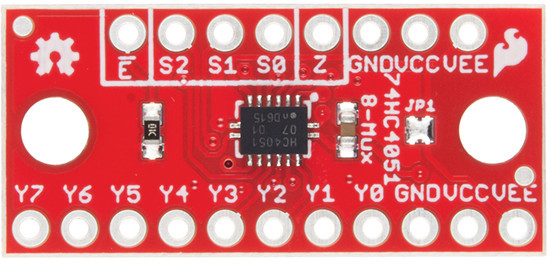
For the project this week I will need more digital pins than the ATTiny44 can offer, thus I started to look for a multiplexer. I was not sure which to choose from the list on DigiKey, I used Google and found a breakout board from SparkFun which features the 74HC4051 8-channel analog multiplexer/demultiplexer. I thought it would also give me the possibility to clean up the PCB design a bit.
The speciffic part was not available on DigiKey, thus I had to choose another one. I went for the Texas Instruments SN74LV4051ADR after checking its datasheet and making sure that it is what I need.
The multiplexer will let me use one pin of the ATTiny44 for all digital sensors and actuators I want to use in my project. The Texas Instrumants SN74LV4051ADR offers 4 I/O pins, each of them can be connected to one of eight I/O pins on the other side by setting the bits on the 3 select lines of the chip. From binary, 3 bits provides us with 8 combinations as 2 ^ 3 = 8.
How about a challenge, I thought. What if I use the ATTiny85 instead of ATTiny44, since the ATTiny85 is smaller. Let’s try to do that. Below is a brief outline, what I want to accomplish this week.
- Redesign PCB to use ATTiny85.
- Make it as a shield for Raspberry Pi.
- Connect SMD version of the 5-way switch.
- Integrate a vibration motor.
- Test it with Raspberry Pi Zero.
There is a lot to do, so let’s get going.
PCB Design
Before starting the design process in Eagle, I want to check the Raspberry Pi Zero GPIO pin layout to be able to design against that. Below you can see an image of thet (borrowed from Shahbaz Ahmed’s Blog).
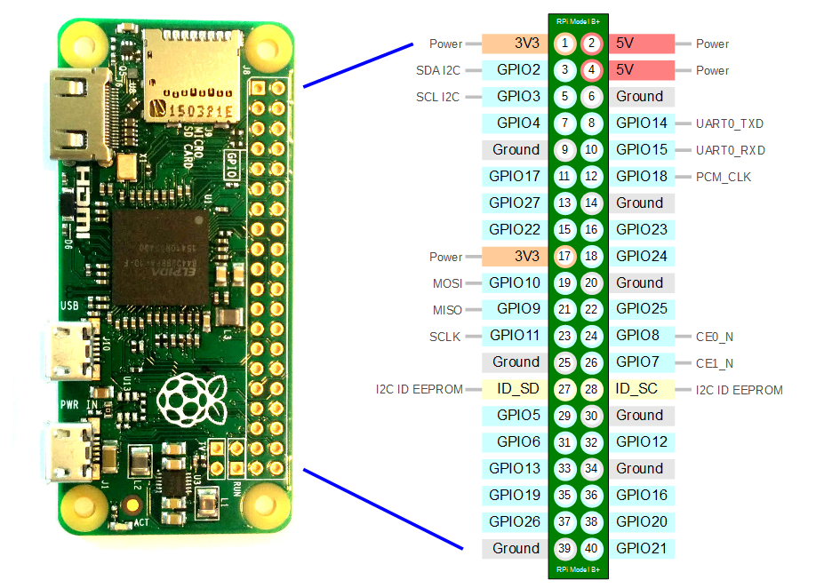
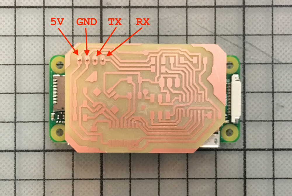
All I need from these pins are the 5V, Ground for power and TX, RX pins for serial transmission. I will need a 4-pin header to connect my custom PCB to the Raspberry Pi. If we look at the previous board designs with the FTDI connector, we can see that two of the FTDI connector pins are not connected and thus not used. For our Raspberry Pi connector we will not solder them to the board at all.
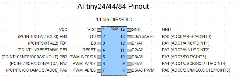
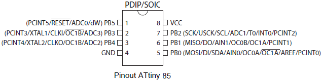
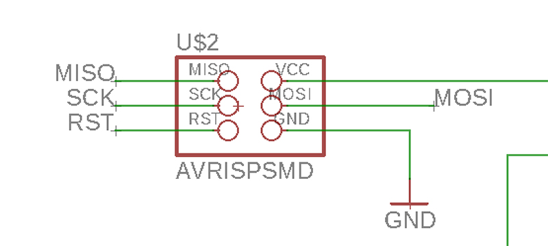
Another thing is the mappings from the ISP connector to the ATTiny85. For that I will need a pin comparison between ATTiny44 and ATTiny85.
Then, let’s take a look at the wirings from the ATTiny44 of the board that I have to the ISP connector.
Now having all of these on the same page, we can build a table with mappings and their differences. I will skip the VCC and GND here.
| Chip | MISO | MOSI | SCK | RST |
|---|---|---|---|---|
| AT44 | PA5 | PA6 | PA4 | PB3 |
| AT85 | PB1 | PB0 | PB2 | PB5 |
At this point I understood that ATTiny85 does not have enough pins for my purpose.
So I skipped the idea of designing a new board around ATTiny85 and kept ATTiny44 as my chip-of-choice. With that in mind I started to draw the schematic in Eagle. Below is a list of main components that I added to the project.
- ATTINY44-20SSU chip (library: Atmel_By_element14_Batch_1-00)
- SN74LV4051ADR multiplexer (generic 4051D, library: 40xx)
- AVRISPSMD ISP connector (library: fab)
- PINHD-1X4 header (library: pinhead)
- COM-10063 (JOYSTICK_MINI) 5-way switch (library: SparkFun-Switches)
- PINHD-1X2 header for connecting the vibration motor (library: pinhead)
- 1K pull-up resistors for the buttons
- A 10K resistor for the RESET connection
I discovered the INVOKE command in Eagle that unhides the hidden pins of a chip. However, below you can see the final schematic for the PCB of the week.
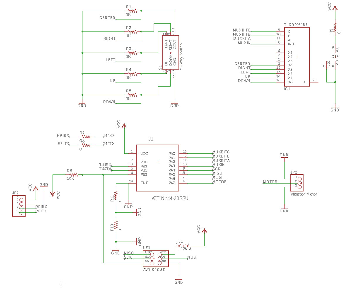
As you can see I integrate the SparkFun 5-way switch directly, I added a muxer and connectors for the vibration motor. Below you can see how the PCB design looks like.
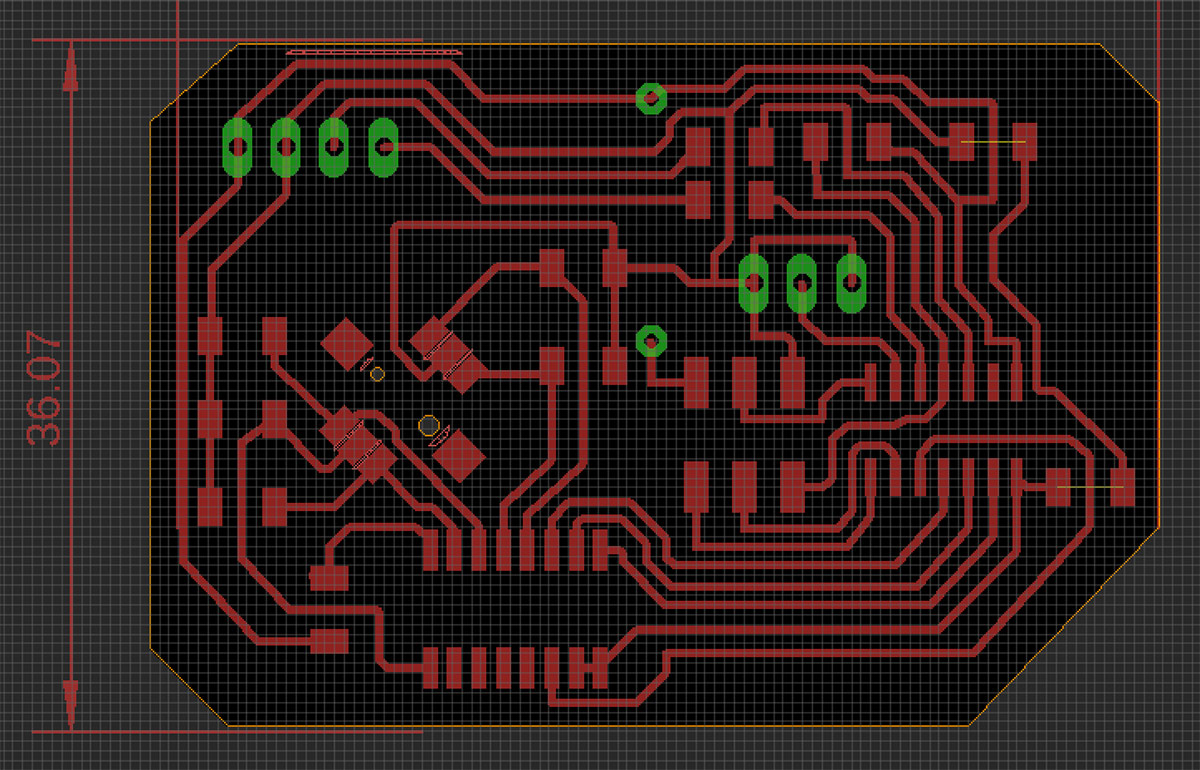
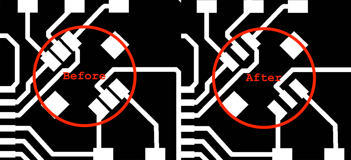
There were some parts in the PCB design that did not pass the DRC (design rule check). I solved them in the PNG image creation phase in Photoshop later. I added extra spacer pixels inbetween the pads that were too close.
I used default settings for the Roland SRM-20 millng machine in Mods and was able to mill the traces, drill holes and cut the board without problems.
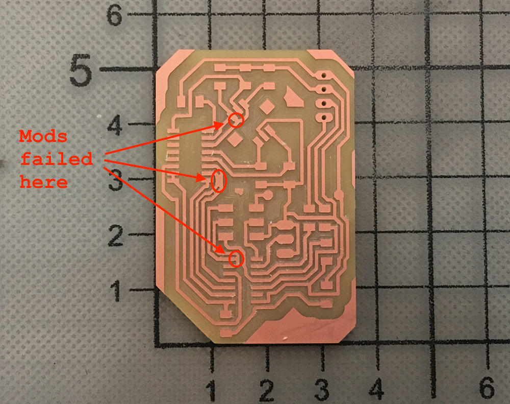
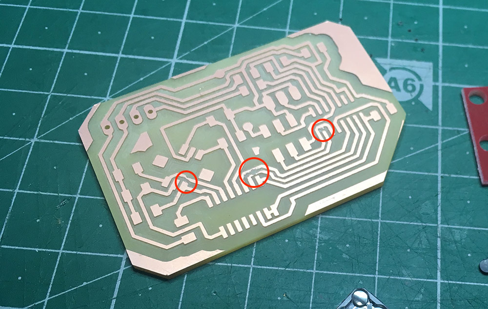
The image above demonstrates that the board is sitting nicely on top of a Raspberry Pi Zero board. There is a 4-pin header between them. Just after adding them to my documentation page, I started to notice places on the PCB where Mods did not really create toolpaths to mill through. I will have to use a dremel in order to fix that.
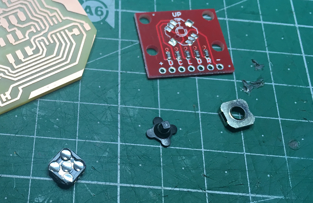
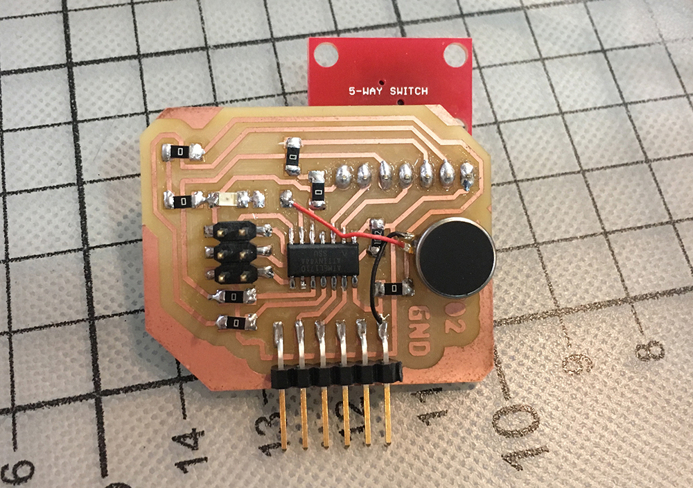
After fixing the PCB with the dremel, I went to remove the 5-way switch from the breakout board since the SMD version of the switches were not there yet. I used a hot air gun (probably too much of it) as the 5-way switch revealed its internals by falling apart. I got stressed at first, since I had only two of them at the point, but it was relatively easy to figure out how to put it together again. It was also possible to see that there is not too much in it and it would be possible to build one from scratch.
I went on to solder the parts. I used flux to cover the PCB pads and it did make the task of soldering much easier. Below you can see the fully assembled board on top of a Raspberry Pi Zero.
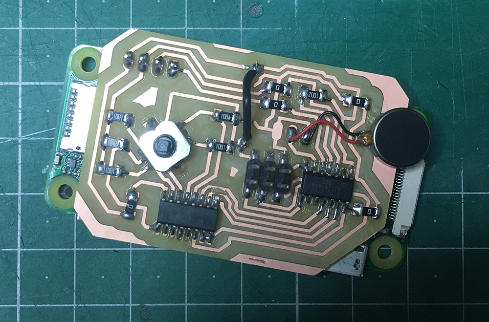
I started to feel weird about the fact that I went on and soldered the PCB on the Raspberry Pi. It was supposed to be a shield. The purpose for me to solder it was to get the board closer to the surface of the Raspberry Pi to reduce the thickness of the full device. I started to look for headers that would be as short as possible.
In order to program the board, I will have to use the Raspberry Pi to power it up. To make sure things run as expected, I will install the latest version (release date 2018-04-18) of Raspbian Lite on it. I am using Etcher for that purpose. It takes .zip with .img files as an input and burns the filesystem on the SD card.
I was able to boot it up and the ISP programmer was showing a green light which would mean that it is able to sense the ATTiny44 chip on the other side. I uploaded a test code which would turn on and off the vibration motor connected to pin PA7.
#define MOTOR_PIN 7

void setup() {
  pinMode(MOTOR_PIN, OUTPUT);
}

void loop() {
  digitalWrite(MOTOR_PIN, HIGH);
  delay(1000);
  digitalWrite(MOTOR_PIN, LOW);
  delay(500);
}
It worked perfectly and it generated the feeling as if there would be a phone ringing (silent mode) somewhere in the room. Next I wanted to trigger the motor whenever one of the buttons would be pressed. For that I needed a bit more complicated code.
Since I am using a multiplexer in my design, what I had to do was to tell it to make a connection with each of the pins where it has the button pins connected in order to read their values. The mapping between the muxer and the buttons is as follows.
14 (Y1) UP
13 (Y0) DOWN
12 (Y3) RIGHT
15 (Y2) LEFT
1  (Y4) CENTER
The input pin of the muxer is connected to pin 10 (PA3) of the ATTiny44. The muxer control bit pin mappings listed below.
A 11 (PA2)
B 12 (PA1)
C 13 (PA0)
In order to access the button direction pins, we will need to use a combination of bits to open the connection. In order to do that, I had to look at the sn74lv4051a datasheet (on page 12).
direction   C B A
UP (Y1)     0 0 1
DOWN (Y0)   0 0 0
RIGHT (Y3)  0 1 1
LEFT (Y2)   0 1 0
CENTER (Y4) 1 0 0
Now it was possible to write the code. In the process I realized that the communication pin (mux pin 3) is not connected. It happened because I thought the INH pin is the communication pin. Luckily there was one free ATTiny44 pin on my board and I went on to connect a jumper cable between mux pin 3 and ATTiny44 PB0 (Arduino 10).
I used the following code and could not get it working anyway. Then I measured the voltage between the muxer pins and the buttons, it appeared that the button does not work as expected. I checked all the directions–nothing. There are two things that might have gone wrong: I destroyed the button while unsoldering; I did not connect it correctly (maybe I should stay with pull-up resistors instead of using pull-down’s).
To get the concept working, I got the board of the input week and added the vibration motor there. Instead of the LED I was trying to turn the motor on and off. It did work, but it seems that the board stops working because of the voltage fluctuations that are caused by running the motor.
Conclusions
It was an interesting journey this week. I managed to get the output device (the vibration motor) working. Adding button to the board was an extra challenge. The fact that it is not working is a good one as I have to design a new board (shield) anyway.
Adding more components to the board (multiplexer and 5-way switch) makes the wiring less manageable and I feel like it is time to try to make a double-sided board. This is going to be one of my final project challanges. Also trying to transform the board into a Raspberry Pi shield was a challenge.
The process would go faster and maybe I would get the 5-way switch working if the parts would arrive on time. The actual 5-way switches take 2 weeks to arrive from Mouser. All in all without failing there is less certainty about the rightness of the design decisions. Now I feel more confident about the way the shield should work.