
Week 10
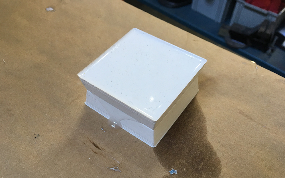
We do molding and casting this week. My goal of the week is to create a case that I could use as a starting point for my final project.
Notes from the Lecture
OOMOO silicon high resolution.
Drystone - cement matrix. Low viscosity. Make very hard parts. Easy to work with.
General recommendation is to use OOMOO for the mould and Drystone for the casting.
Dusting - with a talcum powder. It helps with surface tension. Used in metal casting.
Aluminum casting. High-temp casting. Can EXPLODE !!!
Additives can improve different properties of a material used for casting.
It is a good idea to test the casting material first, find out how to cast it, then make the mould.
Where to buy Smooth-On materials in Spain.
FormX Spain S.L.
C/ Roc Boronat, 39, Local 1 (Pople Nou)
Barcelona, Parada de metro Llacuna - L4 08005
Crystal Clear from Smooth-On is dangerous http://www.formx.es/.
Use protection: gloves, glasses, etc.
3-axis machining can be used to create the mould.
Rough cut - chip removal, good for removing large parts of material.
Finish cut - used in the finish, not efficient for removing large amounts of material.
Carbide Depot - place where to buy 3-axis machining tools for SRM-20, for example.
Carbide Endmils - extra long endmills.
Design around the tool is the recommended approach for the week.
Flat-end’s are generally better for material removal. Most of the time it is better to use a flat-end mill for milling curved surfaces if one uses all 3 axes of the machine.
Depth of cut - be aware of that to not crush your job and the machine.
General workflow is the following.
- Create a positive in wax.
- Create a negative in silicon.
- Use another kind of silicone to create silicone positive at the end.
This is the wax block we are going to use for creating the mold with a milling machine. Its dimensions are 150x100x30mm.
One of the possible approaches for achieving a double-sided mold.
Design walls that are NOT 90deg, leave a RAMP
Painting the inner surface of the mold is a good way to avoid bubbles on the surface.
Vacuum forming machine is another possible approach.
Notes from the Demo
The maximum milling depth should be 35mm. One can use high-density foam for creating molds as well. Here the material is concrete, coated with lack-paint.
The tool that we are going to use for milling on SRM-22 is 3mm in diameter (the shaft is also 3mm). It is the only one that is long enough for the task. 0.79mm tool can be used for smaller details, but you have to take into account the V shape between the end of the shaft and the tip of the tool.
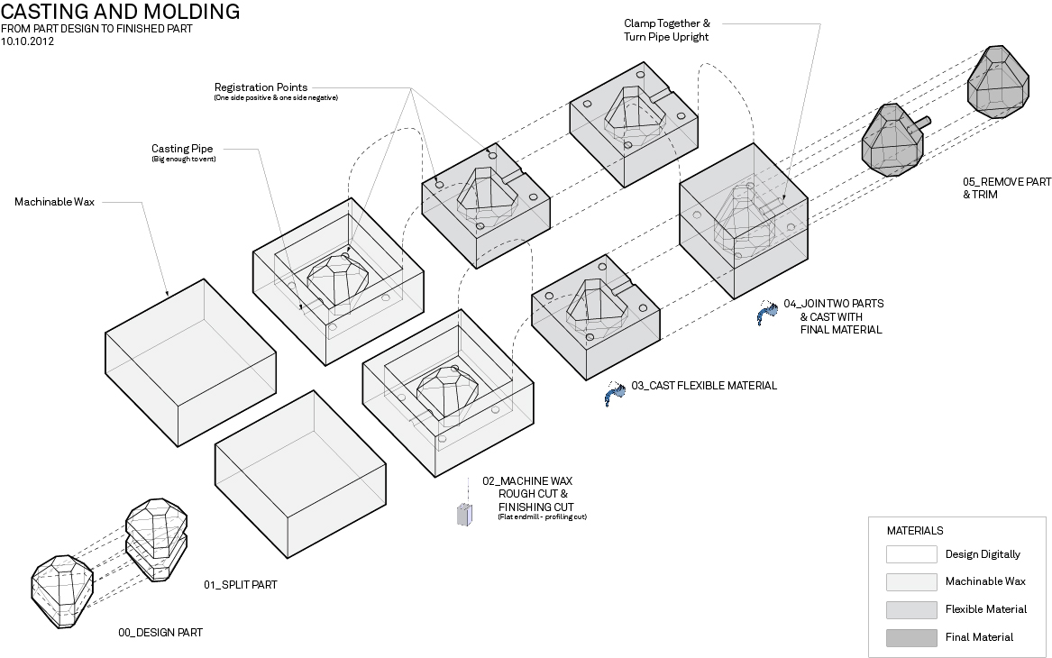
The diagram below (from cba.mit.edu) shows the overall workflow of two-sided casting and molding.
We can use Modela Player 4 for milling the wax mold. But one can use Fusion 360 CAM as well.
It is important to set the origin to left-bottom-top of the material stock.
Notes on Injection Molding
Got link from Joris.
The problem is that this mechine costs 4000, but the one of Precious Plastic 150.
Creating a Mold
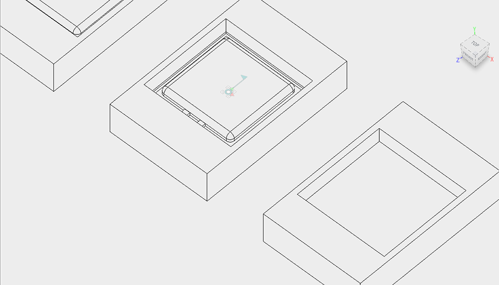
I ussed Fusion 360 to create a mold. I used my experience gained during previous assignments and created a positive 3D model first. The challenge was to figure out mold models for two sides, since the I wanted to create a double-sided object.
After creating the model (and not being sure if it will work), I decied to look for help on YouTube and found some videos with tips and tricks for creating molds in Fusion 360.
The interesting part in the video above is the usage of the Boudary Fill tool to create a negative to calculate the volume of material (silicone in this case) that one is going to use for creating the silicone mold.
While milling the mold, I began to think more about the fact that injection molding with the Precious Plastic approach (which means using their open source injection molding device for melting used plastic bottles and injecting them into an aluminium mold) is what I actually want. I started looking for YouTube videos that would discuss how to do that with Fusion 360. I found the following one which involved a few advanced things (as drilling holes for the water cooling) that could be avoided at least for the first iteration.
The video here is Part 2, if you are new to Fusion 360, it makes sense to watch Part 1 also, since it contains some valuable design tricks. Other advanced things include creating threads, which I am not sure if it is really needed.
First, I decided to make a double-sided mold as an experiment for my final project. I modelled a half of the product casing in Fusion 360 and tried to figure out how to convert it in a positive mold for milling in wax. It was a struggle and I had a 75% sense that it is not going to work.
You can find the design files in my molding and casting GitLab repository.
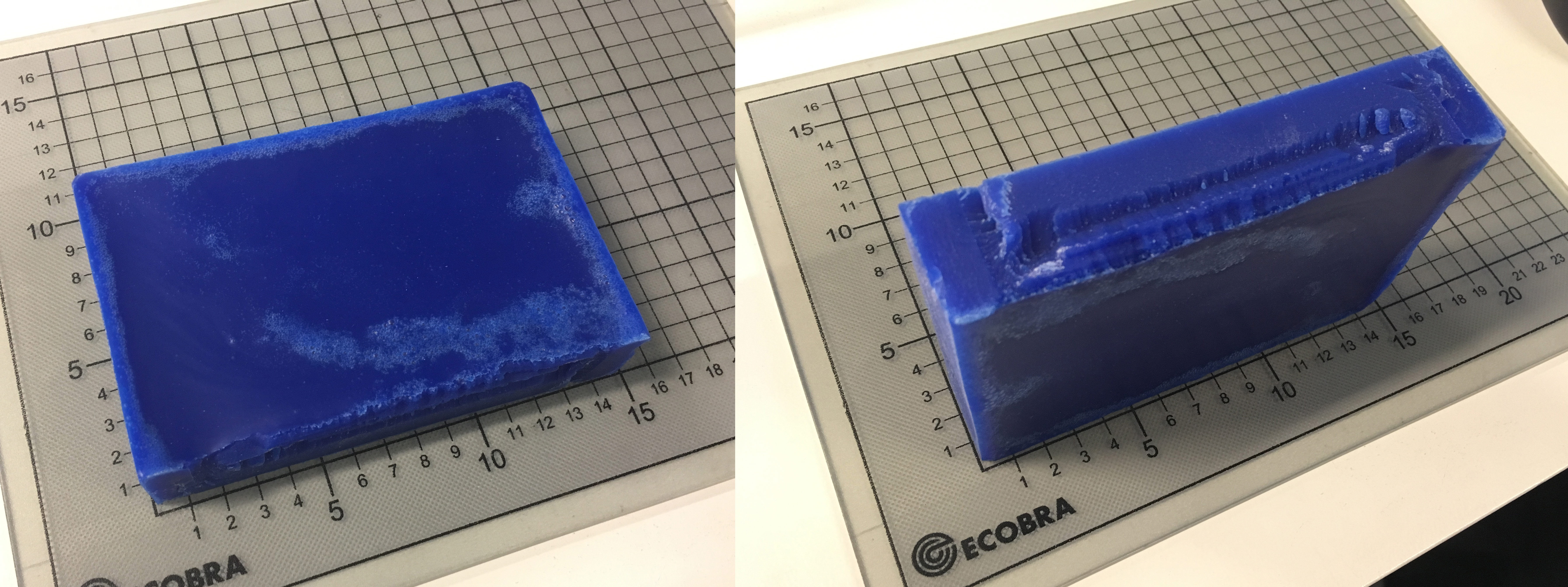
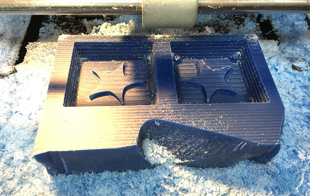
The milling went well, except there were parts where the toolpath was not calculated because of the wrong choice of the endmill. The problem was I used the same flat-end mill also for the finishing operation.
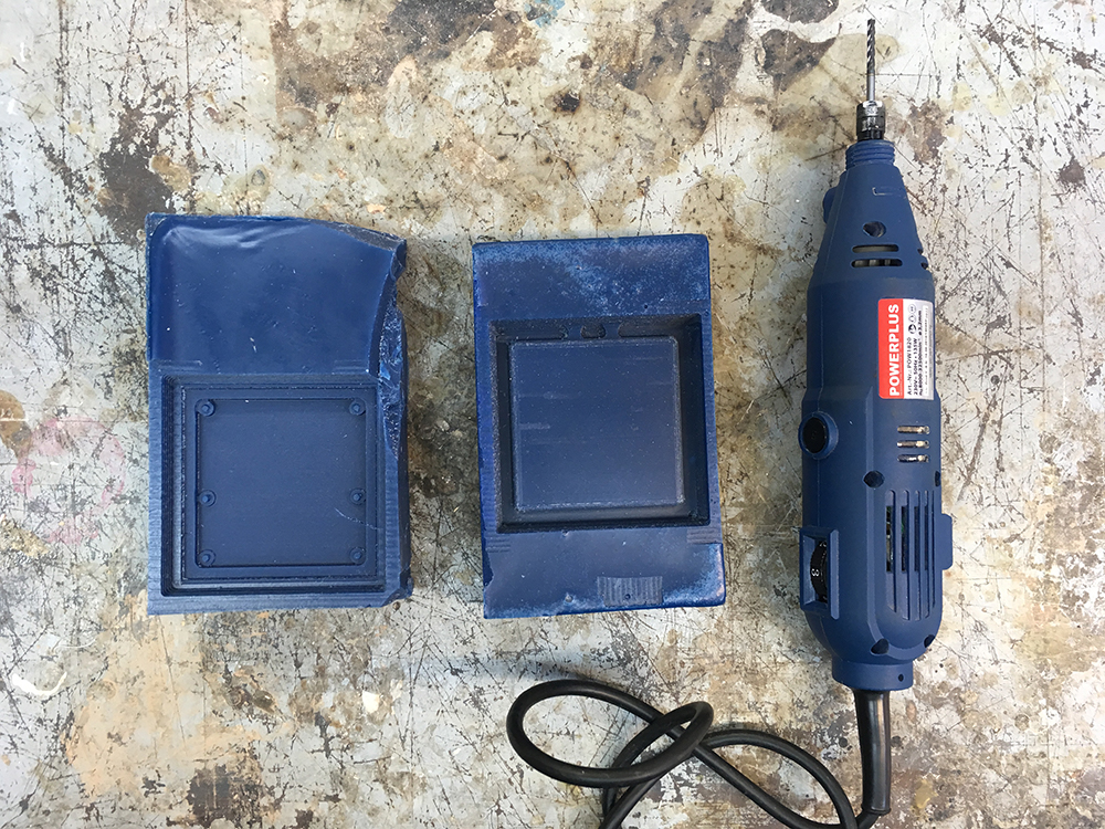
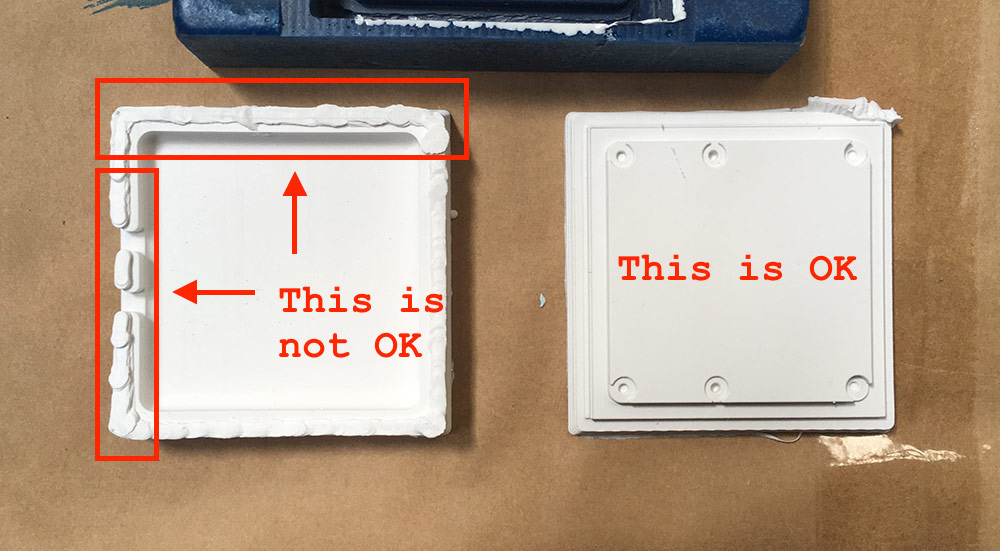
Even though the milling of the positive mold failed, I decided to move further with casting a negative with silicon, just to try out the process. As expected, the outcome was not a success.
Since the failure, I thought of choosing something rather simple and practical. My thoughts were around small things, such as key rings or something that would keep my cables organised. Or something that can be reused for many things. It should be something that would definitely work.
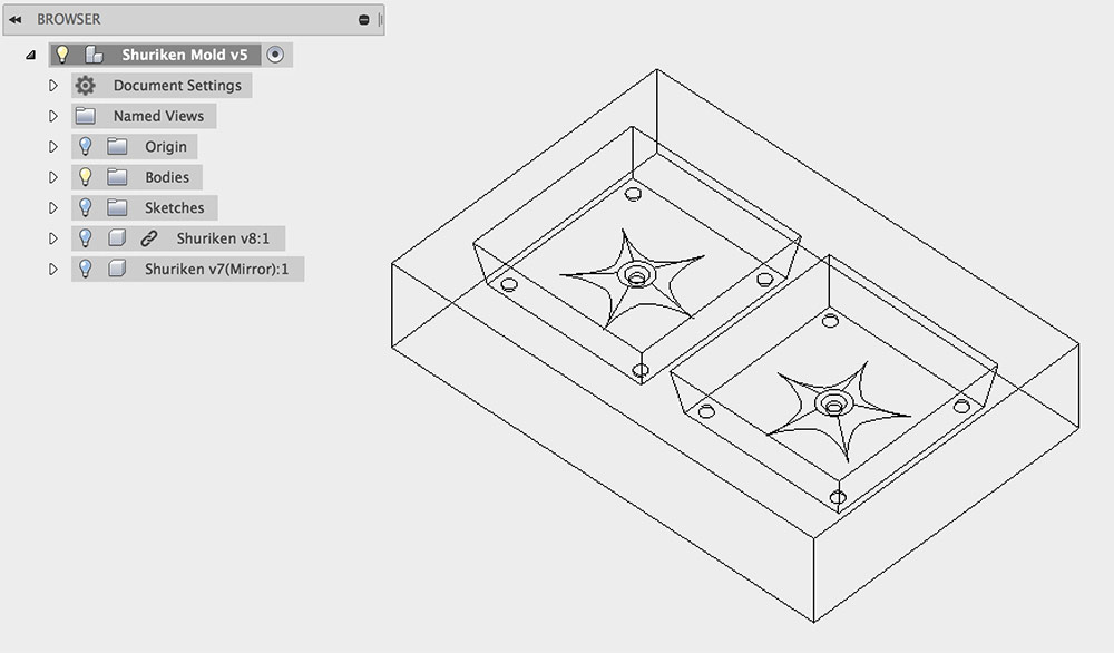
Creating the Parametric Shuriken
I decided to go for a parametric shuriken modelled in Fusion 360. This time I wanted to be smart, thus I decided to create the design of the shuriken as a separate project and to import it into the mold design for further processing.
A few new Fusion 360 things while modelling the shuriken and creating the mold. I learned about the spline tool. The shoulders of the vectors of the spline can be treated as lines, thus one can apply constraints to them and their endpoints.
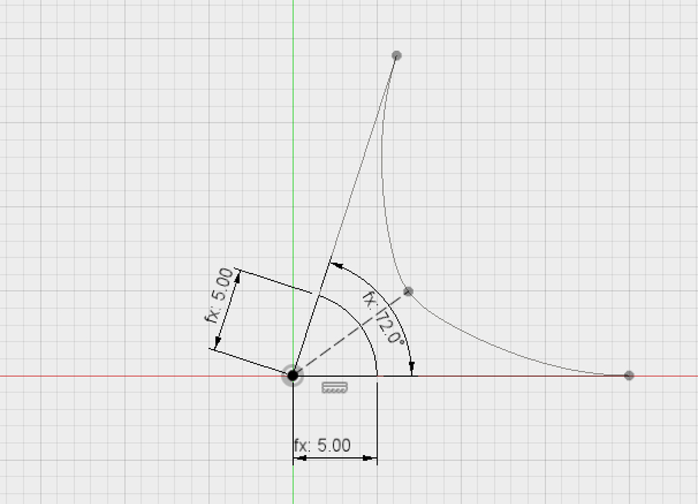
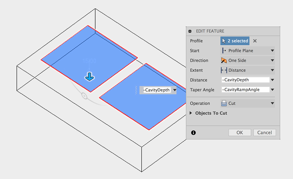
While making the mold, I found a nice way how one can specify the angle of the inwards extruded ramp. In the extrude parameters one can specify the taper angle and it can be a parameter.
You can find the design files on my molding and casting GitLab repository.
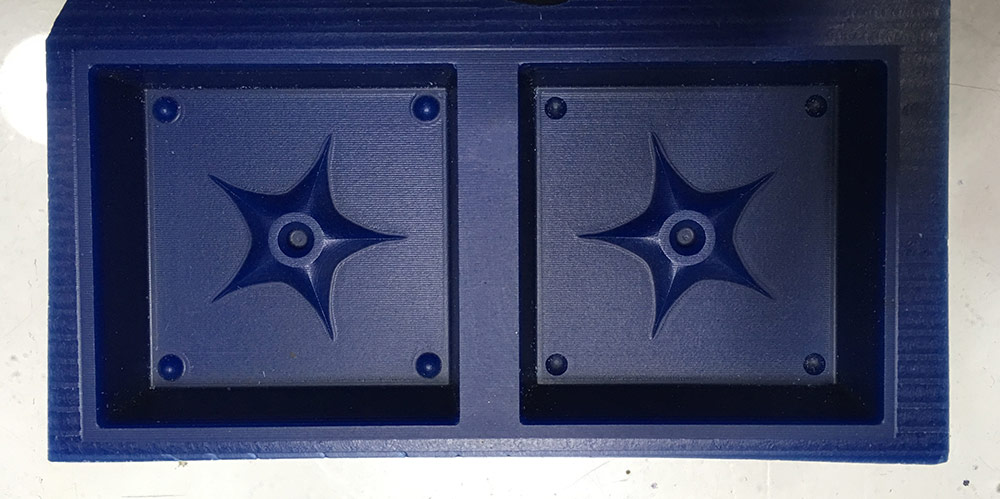
Make sure you have registration points if designing a double-sided mold!
After extruding the registration points, I tried to add a casting pipe. It did not look too good and I predicted problems with removal of them. I figured that I will cast each of the sides separately and then try to glue them together with silicon glue.
After exporting the mold as an .stl file, I went on to use the Modella Player 4 to generate the toolpaths for the SRM-20. The first thing after importing the .stl file one should do is to set model orgin. You can do that by entering the Set → Model menu.
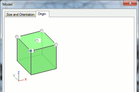
Setting the origin of the model should be the first step in Modella Player 4!
Once that is done, one can start adding operations. I started with the surfacing operation as it is much nicer to work with a flat surface. The following are the operations that I created.
- Surfacing (3.175 flat endmill)
- Roughing (3.175 flat endmill)
- Finishing (3.175 ball endmill)
I had to add a new tool in order to generate the finishing toolpath. Somehow the 3.175 ball endmill was not in the presets. The process is relatively painless. One has to specify the diameter of the tool and the type. Choose cemented carbide as the material of the tool. Then the speeds of the axes have to be set by clicking on the Cutting Parameters button. The general rule is that Surfacing and Roughing speeds should be slower and one can go faster with the Finishing.
Once the toolpath operations are there, click on the Send to Machine button to export toolpaths to a file. Transfer the resulting .prn files to the computer controlling a SRM-20. Use VPanel to calibrate the machine. Make sure you set origins for all axes. Then launch cutting operations one by one.
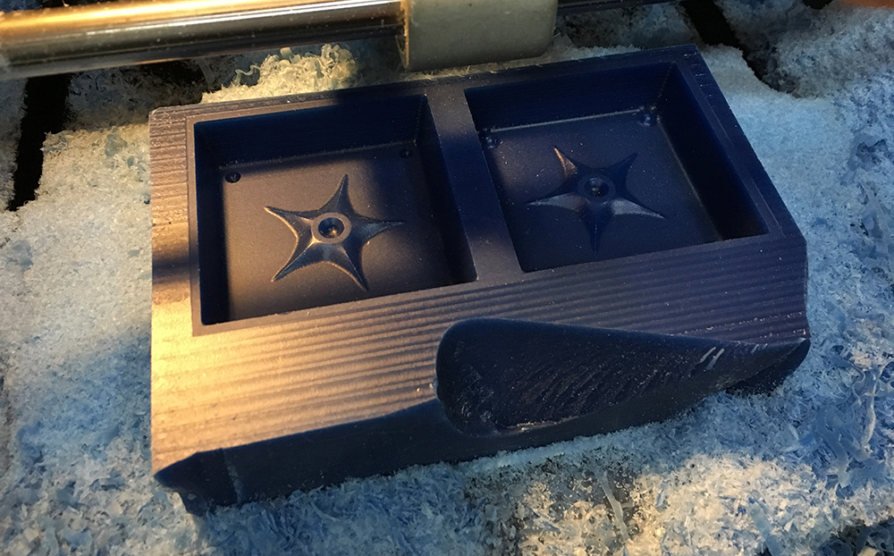
Surfacing.
Roughing.
Finishing.
In my case I trusted the default settings while generating the toolpaths on the Modella Player 4. Thus the cutting depth was too high and I had to go 20% of the speed in order to not to break the machine. During the Finishing phase I could go 150% without problem.
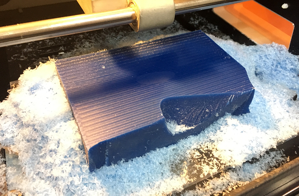
There were some parts where the 3.175mm tool could not get through. Thus I had do create another milling operation with a 1⁄16 ball-end tool. I had to add it to Modella Player 4 before I could generate the toolpath.
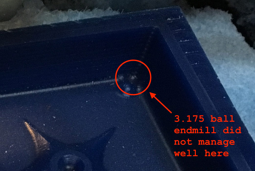
To add it, I had to convert the 1⁄16 inch value to millimeters. 1⁄16 is 0.0625 inches or 1.5875 millimeters. The rest of the settings I had to take from another machine where the tool was already set up.
1⁄16 ball end tool did it well (as you can see in the photo above).
Creating the Negative Shuriken Mold
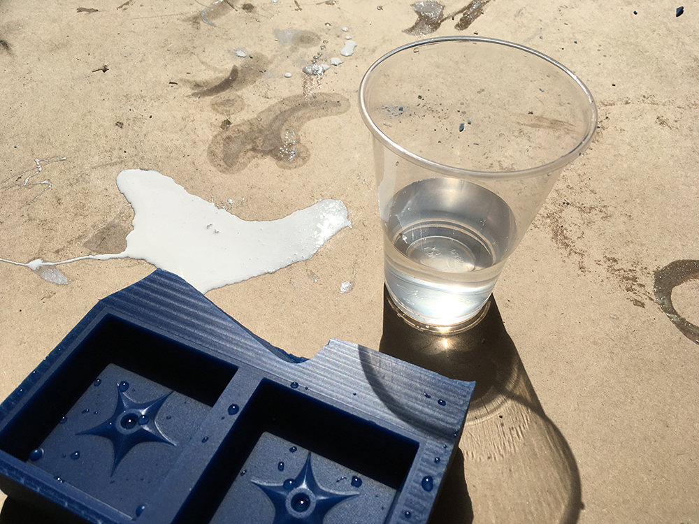
In order to know how much silicone to mix, pour water into the negative wax mold and collect it for optical measurement in a cup.
We used Formsil 25 as the material for creating our silicone molds at the Fab Lab Barcelona. It has two components: A and B. B is the catalyst that has to be added to the main part in order for it to cure. The proportion of the mixture is 95% A and 5% B (as stated on the packaging).
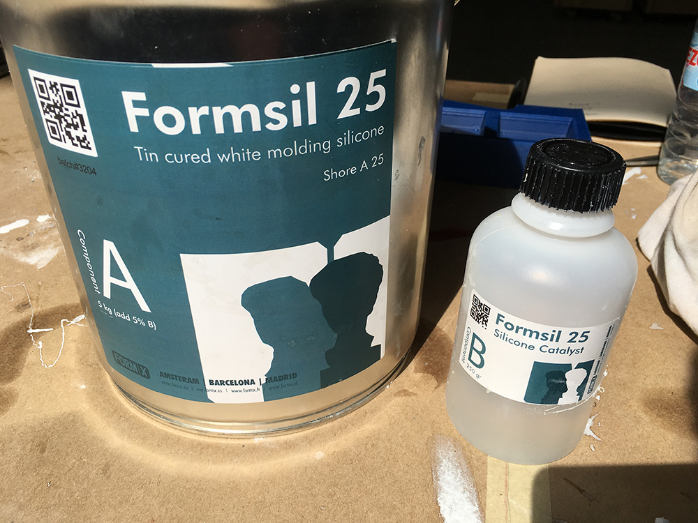
Use scales to measure the right amount of catalyst (Formsil 25 component B) to add.
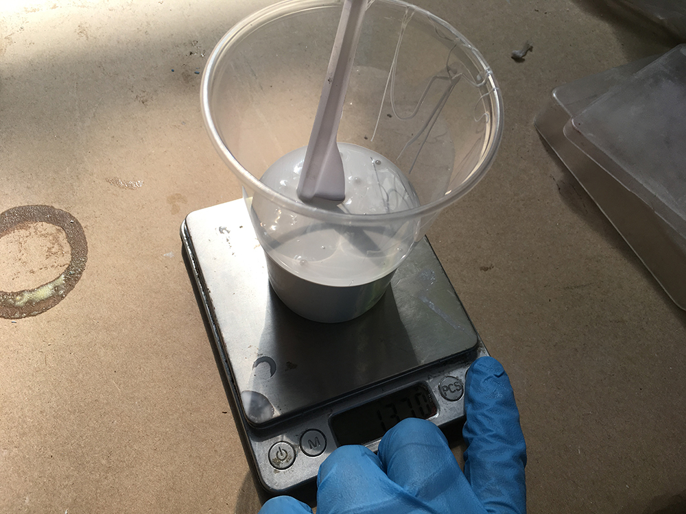
Mix it thoroughly for 15 minutes.
The following video shows how we were told to pour the liquid silicone into the positive wax mold to create a negative silicone mold.
Using the improvised vacuum chamber to minimise bubbles in liquid silicone.
After repeating the vacuum process for about 10 times, I was ready to put my mold next to the others to let it cure.
One day passes here.
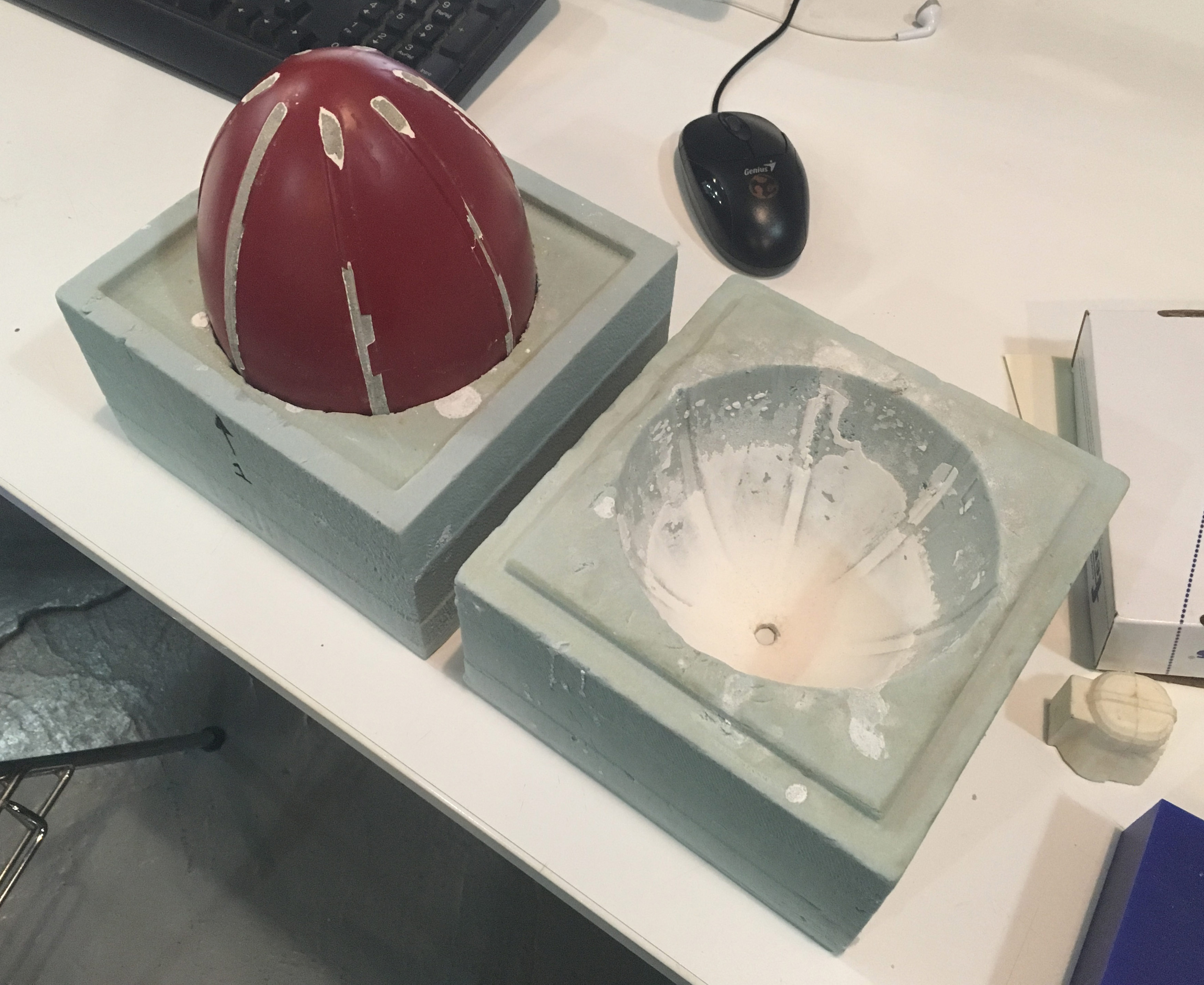
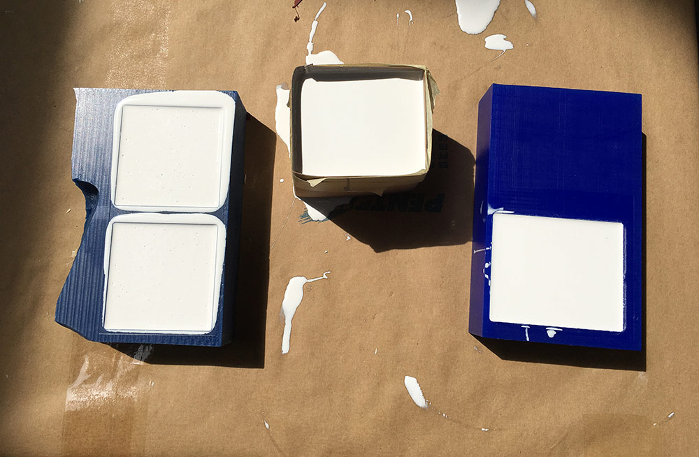
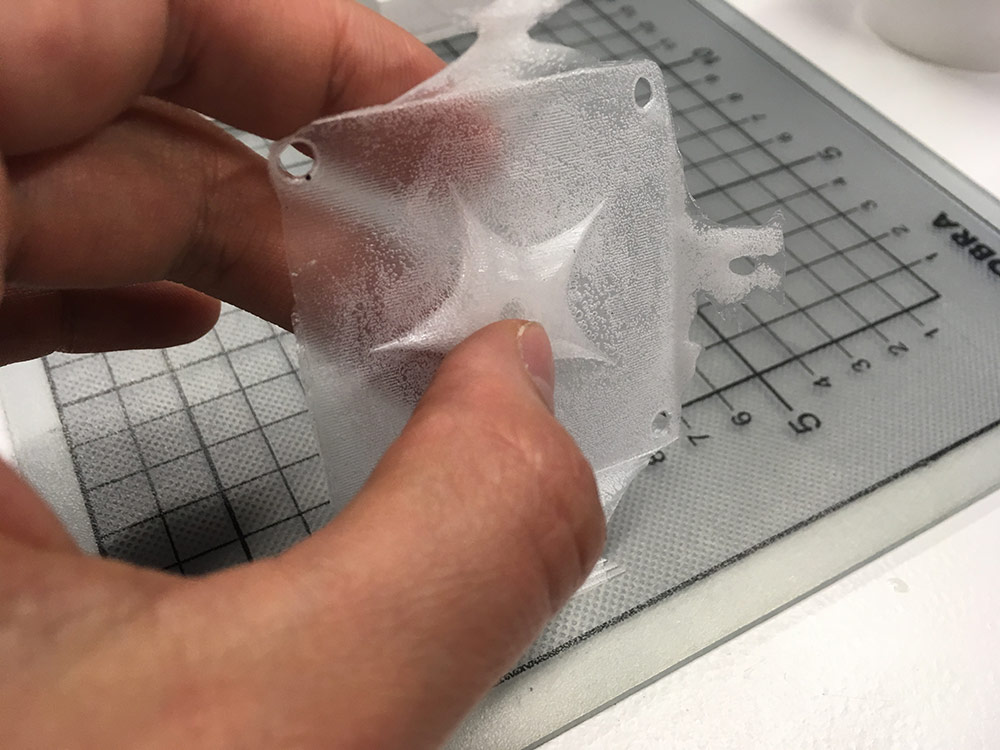
The following image shows the silicone molds I got after coming to the lab the next day. I was very sattisfied and thought that all is going to be good at the end.
Casting the Shuriken
What Are You Waiting For? Make It Now! The box said. I used the high strength liquid plastic from Smooth-On to make my shuriken.
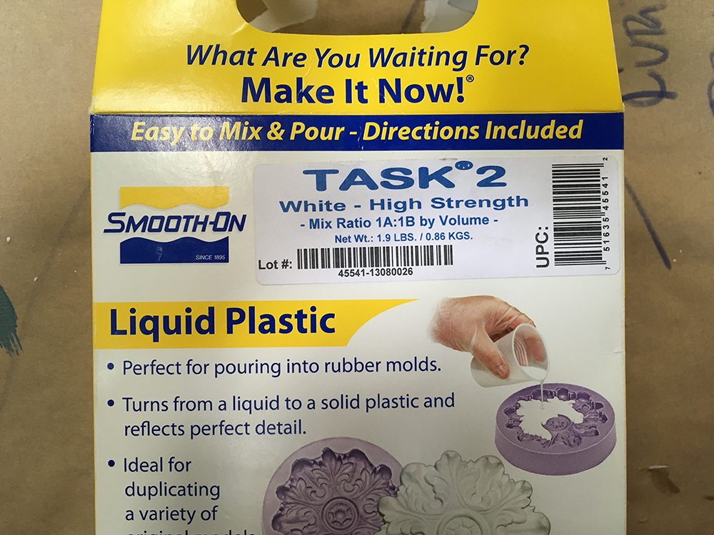
Inside the box one can find two containers (Part-A and Part-B). On the box there is a sticker telling you to mix both in a proportion of 1A : 1B (by volume). Inside though I found an instruction telling me otherwise (this is why this iteration fails later).
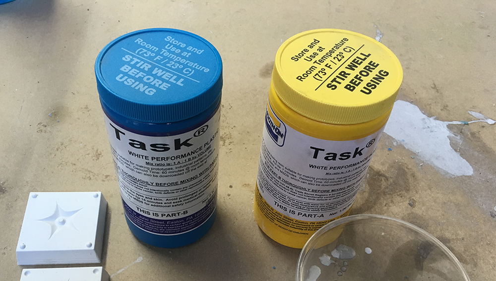
One has to mix it thoroughly for 10 minutes. And then pour it into the silicone moulds.
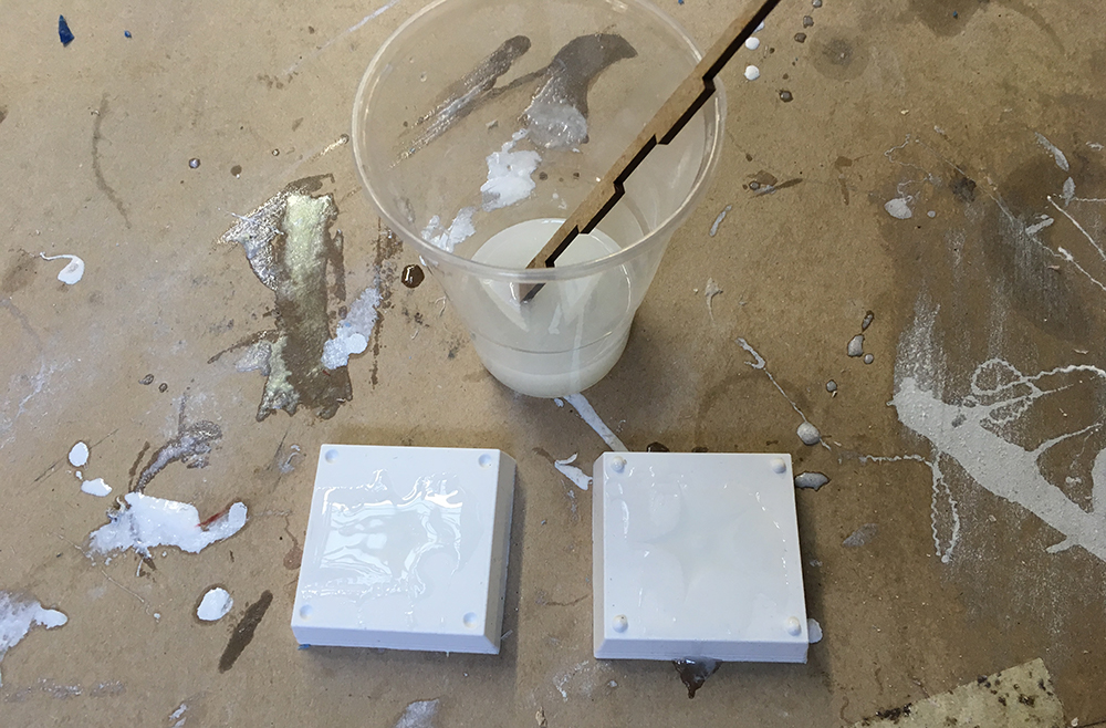
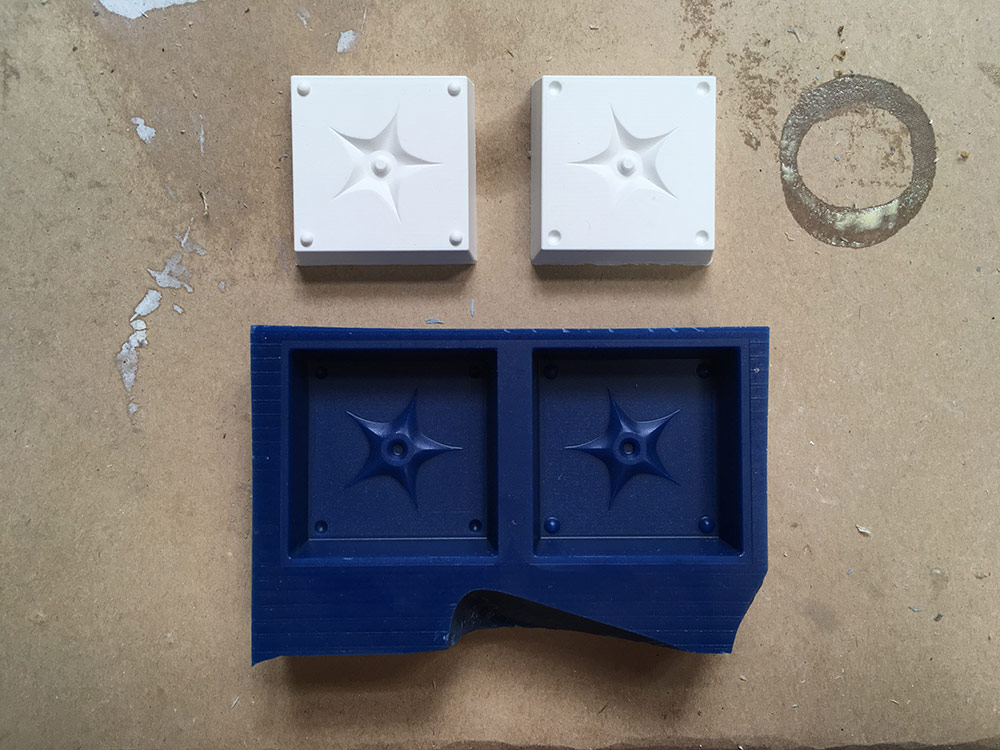
After waiting for a few minutes, I connected the two parts of the mold to connect the both parts.
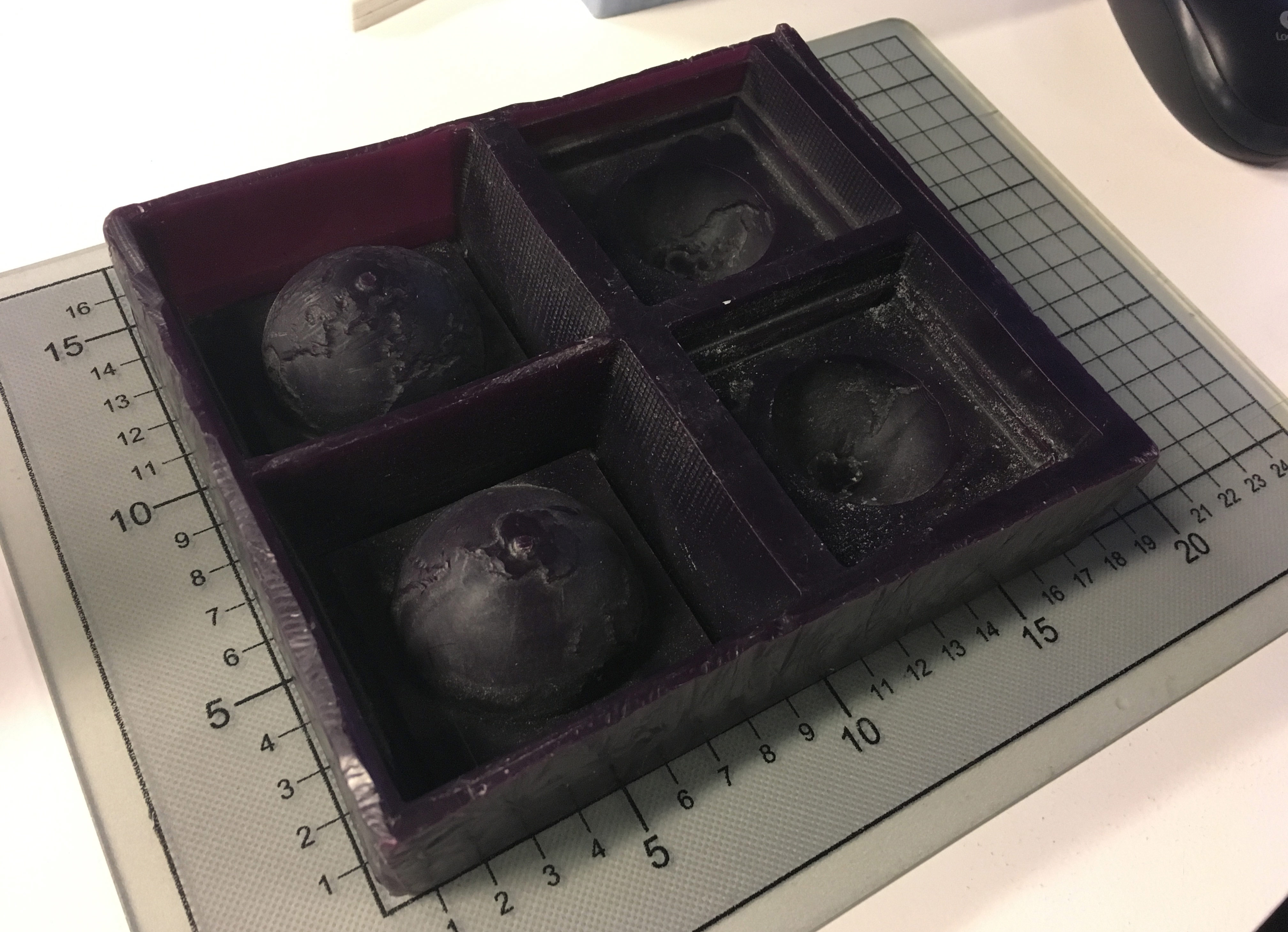
This is how the shuriken came out. You can see that the material got where it should not have went (outside the actual negative cavities). Another thing that you can see is that probably the material was not mixed well before pouring it into the silicone mold.
This is where I decided to stop. You can find all the project files in my Fab Academy GitLab molding-and-casting repository.
About the TASK 2 Resin
Smooth-On TASK 2 resin is low viscosity, high performance casting resin with superior physical and performance properties compared to Smooth-On Smooth-Cast Series general purpose series resins. You can read more about it on the Smooth-On product page.
The TASK 2 resin does not need vacuum degassing.
The mixing proportion is 1A:1B. One should manage to do the mixing in less than 7 minutes. To fully cure the part, one should wait 60 minutes according to the Technical Overview sheet.
Safety. Is important. One should read the Safety Data Sheet before using any of the molding chemicals.
Conclusions
I was looking for ways how to make this assignment compatible with my final project and the initial idea was to try to make housing for electronic parts in it. During my first attempt to do so, I realized that it is not going to work and probably molding and casting in the form we are doing at the Fab Academy is not going to be useful for me.
What I would have liked to look into during this week (or it could be even two weeks) is injection molding and I did watch several videos about it to understand how to make a mold for injection molding in Fusion 360. It does not seem as unrealistic and I am looking forward to try that out soon.
After the first idea of making a case failed, I decided to make something simple and I realized that it is not too simple to cast small and detailed objects. I learned to create a mold and cast an object from modelling it in Fusion 360 all the way to the actual casting process. Too bad that it did not work perfectly, but what I lerned is the process and I could use that for bigger and less detailed objects somewhere.