
Week 13
This week we do things related to interface and application programming. Since my final project has a part where that is needed, to finish this week I will build it, which is a web-based interface for my projection mapping device. I am going to build on top of my solution from the last (Output Devices) week where I created a Raspberry Pi joystick shield for minimal projection mapping capabilities on the fly. The idea is that one can do minimal adjustments with the joystick device and do full project setup by using the web-interface. To get a better sense of what kind of projection mapping I am talking about, below you can see a video to see how my projection mapping workshops look like.
I am building open source projection mapping software ofxPiMapper that runs on the Raspberry Pi minicomputers and as my final project I want to integrate that into a little box that one could use for projection mapping installations. The box would have a physical interface and also a web-based interface, which would become accessible once a computer gets connected to the WiFi network a Raspberry Pi creates around it. The WiFi connection and web interface becomes useful in scenarios when the device is connected to a projector that has no human access.
On the low level there is a C++ application running on the Raspberry Pi that takes care of the projection mapping. A WiFi access point daemon has to run in parallel to open a WiFi network arount the device. Web server is being launched to host the web-interface. The web interface would forward user interface events to the projection mapping application.
The Interface
My project this week is to create a browser-based projection mapping interface based on three.js; it would work as a remote control interface for the projection mapping device running on the Raspberry Pi. Additionally it would have physical search functionality to help identify the device.
The flow of how it works is the following.
- User connects to a WiFi network that a Raspberry Pi spawns.
- User opens the web interface in a browser by using the IP address of the Raspberry Pi
- The interface loads projection mapping project and related assets (images and videos)
- User does projection mapping
Before I start with the WiFi access point configuration, I will make sure that an interface is visible in the web browser. I will start out with a simple HTML page and include the three.js library there.
A few words about threejs. It is a 3D graphics framework for web browsers written by Mr.doob. His real name is Ricardo Cabello and he is a non creative junior developer from San Francisco CA (as stated in mrdoob Twitter profile). At the time of writing this, threejs has 41,175 stars on the threejs GitHub repository which is 175 times more than my projection mapping project ofxPiMapper has. It has 236 stars at this point.
I started out with downloading the threejs release r92 and taking the three.min.js file out of the build folder. I made a basic HTML file to load threejs and put some basic code on top of it. Below is the structure of my HTML file.
<!doctype html>
<html>
<head>
    <title>uMap Interface :: Welcome!</title>
    <meta charset="utf-8">
    <style>
        body { margin: 0; }
        canvas { width: 100%; height: 100% }
    </style>
</head>
<body>
    <script src="assets/three.min.js"></script>
    <script src="assets/main.js"></script>
</body>
</html>
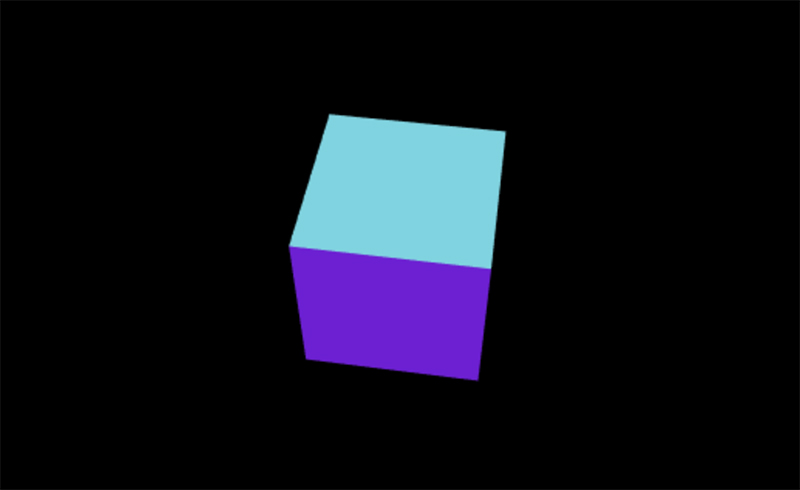
I the assets/main.js file I pasted the example code that you can see on the threejs GitHub repository description. It worked and I could see a cube with colored faces spinning in my web browser.
The next challenge would be to try to construct 3D meshes from scratch and I dived into the documentation and examples of the project. Some time ago I did a demo for an electricity company in Latvia called Latvenergo. It is producing energy locally and also buying it from Russian GazProm (they have a branch in Nigeria that is called NiGaz). With that on my toolbelt I thought it will not take me more than a week to accomplish what I want.
I wanted to replicate the way I construct projection mapping surfaces in ofxPiMapper. What I do there is I create 2D meshes on the Z0 plane. All of the meshes are made out of triangles, the quad mesh also has a perspective warping functionality. In the near future I want to change this so any triangle mesh can benefit from perspective warping.
However the first step with threejs was to figure out how to make a mesh from scratch and display it on the Z0 plane in the browser. In the threejs documentation I found a page about the Geometry class that recommended to use the BufferGeometry class for serious projects. Since my project is serious I decided to save time and dive directly into the features of the BufferGeometry.
An efficient representation of mesh, line, or point geometry. Includes vertex positions, face indices, normals, colors, UVs, and custom attributes within buffers, reducing the cost of passing all this data to the GPU.
This is how you can create a simple quad located on the Z0 plane.
var vertices = new Float32Array( [
    -1.0, -1.0,  0.0,
     1.0, -1.0,  0.0,
     1.0,  1.0,  0.0,

     1.0,  1.0,  0.0,
    -1.0,  1.0,  0.0,
    -1.0, -1.0,  0.0
] );

var geometry = new THREE.BufferGeometry();
geometry.addAttribute( 'position', new THREE.BufferAttribute( vertices, 3 ) );
In the code above two triangles with X, Y and Z coordinates are added in order to form a quad. This made a a spinning red plane that covered almost the whole area of my browser screen.

One of the next things I wanted to do was to add a texture instead of the red color. I went on to explore the Materials part of the threejs documentation. I landed in the Textures page and realized that I need an example.
After checking many texture related examples, I could not find a basic way that would let me specify individual UV coordinates. I used Google to find related information and found this article on StackOverflow which gave me good overview of what I have to do to achieve what I need.
The most important part was to create arrays for vertex and uv coordinates as well as indices that would define which of the quad vertices to use to form triangles. Below you can see the core part of the code to make it work.
var geometry = new THREE.BufferGeometry();

var vertices = new Float32Array( quad_vertices );
var uvs = new Float32Array( quad_uvs);
var indices = new Uint32Array( quad_indices )

geometry.addAttribute( 'position', new THREE.BufferAttribute( vertices, 3 ) );
geometry.addAttribute( 'uv', new THREE.BufferAttribute( uvs, 2 ) );
geometry.setIndex( new THREE.BufferAttribute( indices, 1 ) );
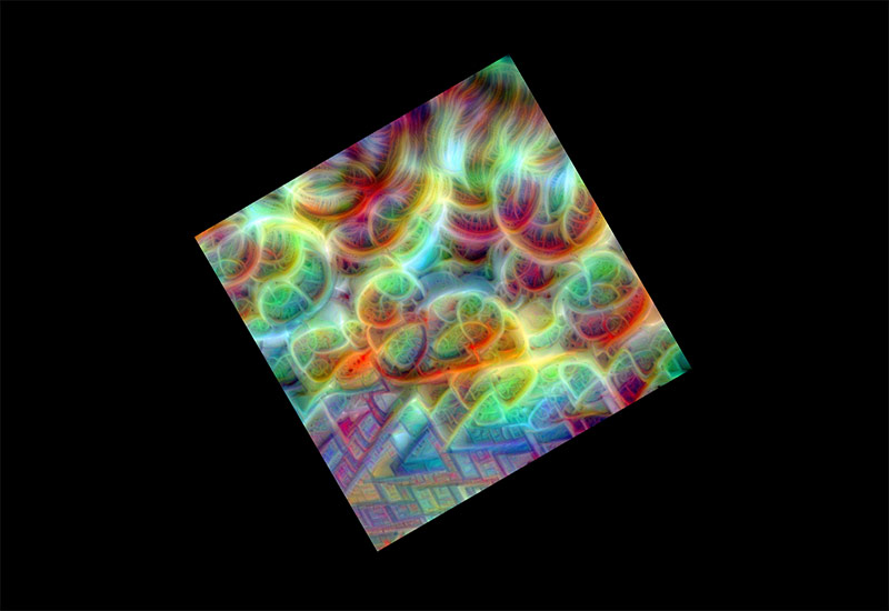
I got a rotating plane with a texture on it. The texture is from the collection of neural network dreams by Gene Kogan.
Next thing I wanted to achieve was to be able to move the vertices of the quad. In order to do that, it appears, that in threejs BufferGeometry object one has to replace the vertex array in order to achieve effects. Which means one has to keep a global copy of the coordinates and animate them before adding to the BufferGeometry again by using its addAttribute() method.
vertices[0] += 0.1;
geometry.addAttribute( 'position', new THREE.BufferAttribute( vertices, 3 ) );
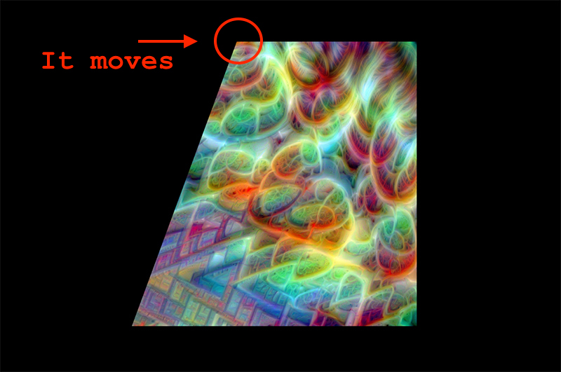
An alternative would be to use the getAttribute() method to copy the stored vertices, do changes on the copy and copy it one more time to the BufferGeometry object. If we keep a global copy, we need to copy it to BufferGeometry only once. At this point the top left vertex of the quad is moving.
Now it is time to use mouse to grab the corners and move them around. In order to do that we are going to use sprites. Sprites are two-dimensional objects in 3D space that always face the camera. In older 3D video games they were used a lot to save processing power. Now they are useful for building 2D interfaces in 3D space. To add sprite handles to the 3D scene, I used the following code.
var handles = [];
var handleTexture = textureLoader.load('textures/handle.png');
var handleMaterial = new THREE.SpriteMaterial( { map: handleTexture, color: 0xffffff } );

for(var i = 0; i < vertices.length; i += 3){
    var x = vertices[i];
    var y = vertices[i + 1];
    var z = -100;

    var handleSprite = new THREE.Sprite( handleMaterial );
    handleSprite.position.set(x, y, z);
    handleSprite.scale.addScalar(handleScale);
    handleSprite.vertexMapping = i;
    scene.add( handleSprite );
    handles.push(handleSprite);
}
What happens above is that on top of the scene, we create another container handles that we use to keep track of the handle sprites only. After creating the handleTexture and handleMaterial, we dive into the array of the vertices of our surface and jump through it with threefold steps i += 3. For each step we get x, y and z.
A handleSprite is created and we apply position, scale and vertexMapping to it. vertexMapping assigns the handle to a position in our vertex array so we can later access the globally stored coordinates of it. Lastly for this block we add the handleSprite to our 3D scene and the handles array.
In order to move the handles along with the vertices, I used the DragControls class by zz85 and mrdoob that comes as a module for threejs. It is a simple way to enable click-and-drag functionality in threejs. Below is the code.
dragControls = new THREE.DragControls( handles, camera, renderer.domElement );
dragControls.addEventListener( 'drag', function( event ){
    var i = event.object.vertexMapping;
    var position = event.object.position;
    vertices[i] = position.x;
    vertices[i + 1] = position.y;
    geometry.addAttribute( 'position', new THREE.BufferAttribute( vertices, 3 ) );
});
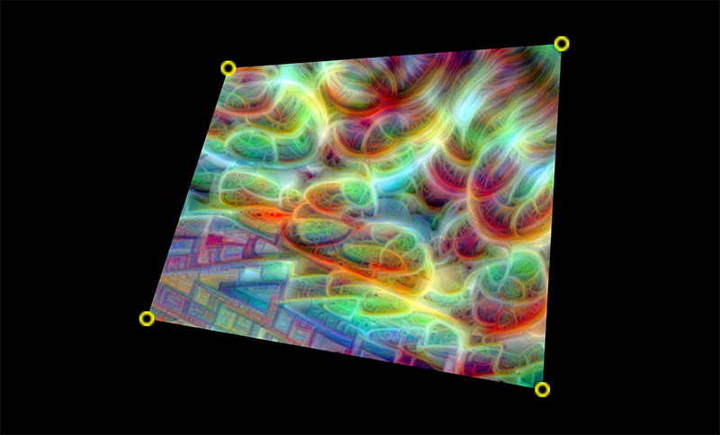
Notice the var i = event.object.vertexMapping; line where we get the position in the global vertex array that is related to the specific handle that we are detecting via the drag event. We set the global vertex position through vertices[i] and then add the updated array as an attribute to the geometry object of our surface. It works! Look at the image below.
With this done, the next step is to optimize code to load existing ofxPiMapper configuration which is an XML file. The ofxPiMapper software creates a file called ofxpimapper.xml where it stores information about the current projection mapping composition. The structure of it looks as the one following.
<surfaces>
    <surface type="1">
        <vertices>
            <vertex>
                <x>50.000000000</x>
                <y>50.000000000</y>
            </vertex>
            ...
        </vertices>
        <texCoords>
            <texCoord>
                <x>0.000000000</x>
                <y>0.000000000</y>
            </texCoord>
            ...
        </texCoords>
        <source>
            <source-type>video</source-type>
            <source-name>gene-nsynthesis-loop-b.mp4</source-name>
        </source>
        <properties>
            <perspectiveWarping>1</perspectiveWarping>
        </properties>
    </surface>
</surfaces>
The top level of the XML structure is the <surfaces> tag. It holds an array of <surface> elements each of which have a defined type, an array of vertices, texture coordinates, source and additional extra properties. For my first prototype of the web interface I need the following data from the XML file.
- Number of surfaces
- Vertices for each surface
- Texture coordinates
- Source type and path to it
ofxPiMapper has a feature that is called generative or FBO sources. The visual content is generated by an algorithm (not an image or video file). There is no file to load, and it would take too much resources for the JavaScript engine to visualize those in the browser. I can imagine a way it would work, but it is out of the scope of this course. Therefore I will focus on image and video sources.
To load and parse an XML file I will need a few extra JavaScript libraries. Threejs is already a pile of code, thus let’s see what is there to reuse. There is the FileLoader class for loading files available. For parsing XML we won’t need an extra library since there is the DOMParser which is available in all major browsers.
Below is how to use the FileLoader to load an XML file. In this case we define the event handlers separately, but one could also specify them inline as anonymous functions for the loader.load().
function opmOnLoaded ( data ) {
    console.log( data );
}

function opmOnProgress ( xhr ) {
    console.log( (xhr.loaded / xhr.total * 100) + '% loaded' );
}

function opmOnError ( err ) {
    console.error( err );
}

loader.load(
    'ofxpimapper.xml',
    opmOnLoaded,
    opmOnProgress,
    opmOnError
);
This works, now XML has to be parsed and transformed into data structures that can be easily used by JavaScript. What I am aiming for is a multidimensional array of objects. JSON or JavaScript Object Notation is the preferred data format in JavaScript. It takes less space compared to XML documents and is still relatively easy to read for humans. Below is what I want to get.
var surfaces = [
    {
        vertices: [
            { x: 10.0, y: 0.1 },
            { x: 100.0, y: 5.3 },
            ...
        ],
        texCoords: [
            { x: 1.0, y: 0.1 },
            { x: 1.0, y: 0.1 },
            ...
        ],
        source: {
            type: 1,
            name: 'movie.mp4'
        },
    }
];
To get it parsed we are going to define the contents of the opmOnLoaded() function. It takes data as its parameter, it contains the contents of the .xml file. I created a few data types to be used.
function Vertex (x, y, z) {
    this.x = x;
    this.y = y;
    this.z = z;
}

function TexCoord (x, y) {
    this.x = x;
    this.y = y;
}

function Source (type, name) {
    this.type = type;
    this.name = name;
}

function Surface(vertices, texCoords, source){
    this.vertices = vertices;
    this.texCoords = texCoords;
    this.source = source;
}
By doing this I make it easier to understand the data structures in case the loaded project file is relatively large. Using custom parsing code that translates DOM objects into my data structures, I am calling the create() function that I made as a separate module that creates 3D mesh objects out of the surface data. I will stop adding big chuks of code here, please browse to the end of the page in order to see the link to the full source code.
There were some problems I experienced along the way. First of all, the values coming from XML had to be parsed as float values using parseFloat() function.
var domSurface = doc.getElementsByTagName('surface')[i];

var vertices = [];
for ( var j = 0; j < domSurface.getElementsByTagName('vertex').length; j++ ) {
    var vertex = new Vertex(
        parseFloat(domSurface.getElementsByTagName('vertex')[j].getElementsByTagName('x')[0].firstChild.nodeValue)*.1,
        parseFloat(domSurface.getElementsByTagName('vertex')[j].getElementsByTagName('y')[0].firstChild.nodeValue)*-.1,
        0.0
    );
    vertices.push(vertex);
}
Another thing was that the y axis was flipped. In openFrameworks the default drawing area is made so that the x value increases from left to right and the y value increases from top to bottom. The origin of the coordinate system is in the top left corner of the window.
In threejs the origin is in the center of the screen. The x axis points to the right, but the y axis goes up. I had to multiply the value of the y axis by -1 in order to make it work. I also had to scale it down by 10 (by multiplying with -0.1) times to match my current 3D scene settings.
I managed to get it working and the surface became visible in the bottom right part of the browser window. The handles were there and it was possible to warp the quad surface.
Next step is to make it so that the coordinates of the vertices are being sent to the application. Before I do that, I wanted to arrange things so that I do not have to scale the incoming coordinates. In order to solve that, I was hoping for the features of the OrthographicCamera. I also wanted to move the origin of the canvas to the top left corner of the browser window and flip the y axis to point downwards.
Both of the things were possible with the following lines of code.
camera = new THREE.OrthographicCamera(
    0, window.innerWidth,
    0, -window.innerHeight,
    0, 1 );

camera.rotation.x = Math.PI;
In the code above we create a orthographic camera by specifying the left, right, bottom and top values for the frustum area. In the previous attempts the loaded surface appeared in the bottom right quadrant of the view. This means that we need to specify y0 as the bottom and negative value or -y800 as the top.
Frustum is a three-dimensional part of a 3D object. In 3D graphics it is part of 3D space where calculations take place in order to generate image for a virtual camera or in other words your screen.
One more thing had to be done since now the camera was looking at the 3D surfaces from the back side. The material had to be adjusted in order to display texture on the back side of the mesh. In order to do that, I had to specify the side property when creating material for a surface mesh.
material = new THREE.MeshBasicMaterial( {map: texture, side: THREE.BackSide} );
It is the THREE.BackSide that tells threejs to display texture on the back side of a mesh. In the case of a closed 3D object it would mean that it would be invisible from the outside, but become visible once the camera would be positioned inside the object.
To complete the loop, I had to move forward. Next step is to configure the Raspberry Pi to spawn a WiFi network and host the interface that loads the configuration file of an actual ofxPiMapper installation. Let’s start with configuring the WiFi.
I was using a Raspberry Pi 3 here, since I had one with installed Raspbian Jessie and a working ofxPiMapper installation in front of me. First, I used SSH to connect to it.
ssh pi@192.168.1.140
I made sure that ofxPiMapper is installed and running by navigating to its installation directory under /home/pi/openFrameworks/addons/ofxPiMapper and made sure that I have the latest version by running git pull. After I entered the example_basic directory and recompiled it.
cd example_basic
make
It takes more or less time, depending if you have compiled it before. In my case I did, thus after a minute it was done. If the compilation is successful, one can see the following message with instructions how to proceed.
compiling done
to launch the application

cd bin
./example_basic

- or -

make RunRelease
Running it was a success and I could move to the next step. In order to make an access point out of a Raspberry Pi one does not need extra peripherals. There is a WiFi chip on the Raspberry Pi 3 which also has the ability to serve as an access point.
First of all, we need extra software. In order to transform the Pi into a working access point, we will need two packages: dnsmasq and hostapd. While connected to the Raspberry Pi via SSH one uses the following to get them installed.
sudo apt-get install dnsmasq hostapd
We have to edit the dhcpd config file in order to disable dynamic host configuration protocol for the wireless interface.
sudo nano /etc/dhcpcd.conf
Add denyinterfaces wlan0 before any interface lines you may encounter. Then open the network interfaces configuration file.
sudo nano /etc/network/interfaces
Configure our wireless network around the wlan0 network interface.
allow-hotplug wlan0
iface wlan0 inet static
    address 172.24.1.1
    netmask 255.255.255.0
    network 172.24.1.0
    broadcast 172.24.1.255
#allow-hotplug wlan0
#iface wlan0 inet manual
#    wpa-conf /etc/wpa_supplicant/wpa_supplicant.conf
What we do here is we specify the IP address of the Pi to be 172.24.1.1. The other parameters define our network even further, but I won’t cover these details here.
Notice that I commented out the wpa-conf line. It is used to load wpa_supplicant.conf file that describes a network we would like to connect to. In our case we want to spawn a network instead, thus we do not need to be configured as client.
Next we configure hostapd (Host Access Point Daemon) to spawn our network. This is the part that we would like to change later if needed, mainly the network name or SSID, password, etc. In order to be able to do that, we will create the configuration file on the /boot partition, which is formatted as FAT32 and thus readable (and writeable) by most operating systems, including Windows and Mac OS, not just Linux, since Raspbian is Linux and its main partition uses ext file system.
sudo nano /boot/hostapd.conf
Fill it with the following content.
# This is the name of the WiFi interface we configured above
interface=wlan0

# Use the nl80211 driver with the brcmfmac driver
driver=nl80211

# This is the name of the network
ssid=opm

# Use the 2.4GHz band
hw_mode=g

# Use channel 6
channel=6

# Enable 802.11n
ieee80211n=1

# Enable WMM
wmm_enabled=1

# Enable 40MHz channels with 20ns guard interval
ht_capab=[HT40][SHORT-GI-20][DSSS_CCK-40]

# Accept all MAC addresses
macaddr_acl=0

# Use WPA authentication
auth_algs=1

# Require clients to know the network name
ignore_broadcast_ssid=0

# Use WPA2
wpa=2

# Use a pre-shared key
wpa_key_mgmt=WPA-PSK

# The network passphrase
wpa_passphrase=fablabbcn

# Use AES, instead of TKIP
rsn_pairwise=CCMP
Now we have to tell hostapd where the configuration file resides. In order to do that we have to edit the /etc/default/hostapd file and set up the DAEMON_CONF variable.
sudo nano /etc/default/hostapd
Uncomment the line starting with DAEMON_CONF so it looks like the following after.
DAEMON_CONF="/boot/hostapd.conf"
One last thing before we reboot. We have to configure dnsmasq to assign IP addresses to the computers that connect to the WiFi access point we will create in 5 minutes. To do that, backup existing /etc/dnsmasq.conf file first. Create a new one and open it right after.
sudo mv /etc/dnsmasq.conf /etc/dnsmasq.conf.bkup
sudo nano /etc/dnsmasq.conf
Fill it with the following content.
# Use interface wlan0
interface=wlan0

# Explicitly specify the address to listen on
listen-address=172.24.1.1

# Bind to the interface to make sure we aren't sending things elsewhere
bind-interfaces

# Forward DNS requests to Google DNS
server=8.8.8.8

# Don't forward short names
domain-needed

# Never forward addresses in the non-routed address spaces.
bogus-priv

# Assign IP addresses between 172.24.1.50 and 172.24.1.150 with a 12 hour lease time
dhcp-range=172.24.1.50,172.24.1.150,12h
Now it is the time to try if it works. If in case it does not, do not worry, there is still the keyboard and screen connected to the Raspberry Pi directly or the wired ethernet connection that can help you to get things working again. Also, if it is hostapd related, one can edit the hostapd.conf file located on the SD card of the Raspberry Pi. Let’s reboot and see what happens.
sudo reboot
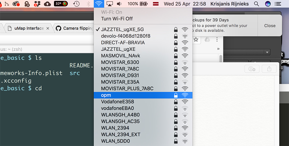
In my case it worked without problem and I could see the opm network on the list of available WiFi networks.
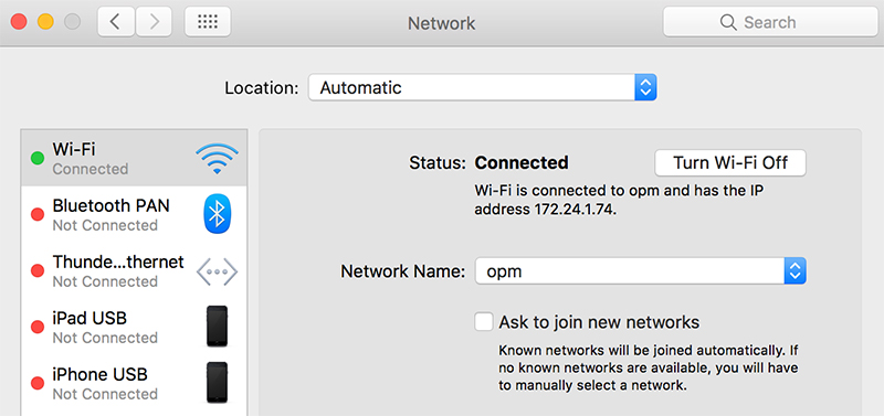
The access point was set up with the password fablabbcn, let’s try to connect using that. It worked and in the network settings I could see that my computer has the IP address 172.24.1.74 assigned by the Raspberry Pi.
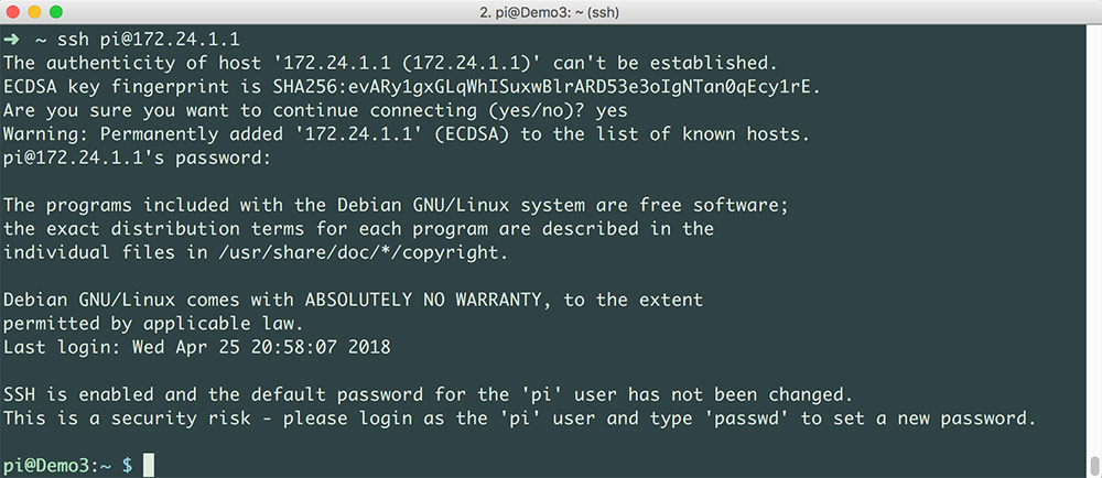
Since we are on the same network with the Raspberry Pi now, let’s try to SSH into it. From the Raspberry Pi network interface configuration above, the IP address of our Raspberry Pi is 172.24.1.1.
ssh pi@172.24.1.1
We are in!
Now we are ready to host our projection mapping web interface. First thing is to copy it to the Raspberry Pi. There are many ways to do it, scp is one among them. scp stands for secure copy, it is a command line utility for copying files over network. Its authors are Timo Rinne and Tatu Ylonen.
Run the following from the directory that you want to copy over to the Raspberry Pi. In my case it is called umap-interface. It will ask for the password of the user pi on the Raspberry Pi.
scp -r ../umap-interface pi@172.24.1.1:/home/pi/
Now we are ready to host our interface. In order to do so we can use the web server that comes with python: the SimpleHTTPServer. To launch it run the following on the Raspberry Pi.
cd /home/pi/umap-interface
python -m SimpleHTTPServer 8080
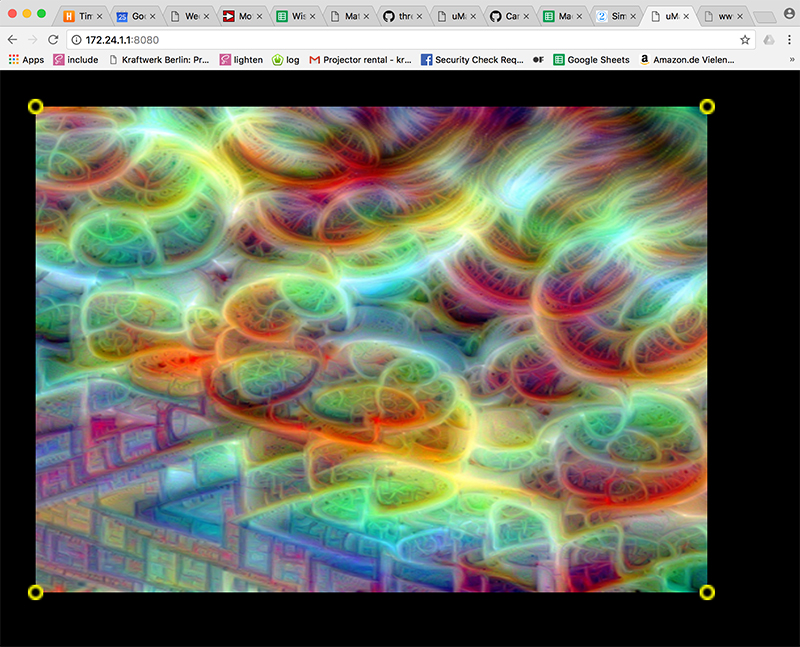
Now the interface is accessible, use the following in the web browser of your computer to access it.
http://172.24.1.1:8080/
I could load the page and start to play around with the interface.
In order to load the actual ofxPiMapper configuration file we will need to create a symbolic link in the web server directory that points to the file outside of it, since it is not possible to access files outside the hosted directory.
rm ./ofxpimapper.xml
ln -s /home/pi/openFrameworks/addons/ofxPiMapper/example_basic/bin/data/ofxpimapper.xml ./ofxpimapper.xml
Since we are not that far and are not loading the actual textures yet, I am not configuring the path to the place where the actual image and video sources are located. This should be enough for the web interface to be able to load the actual .xml file.
The next challenge is to send updates to a running ofxPiMapper instance. For that we will not use the example (thus we will change the symbolic link once more later), but the example_remote-server. It has an integrated TCP server waiting for incoming TCP messages. Instead of using it directly, I am going to tweak it for this assignment. But before I will try to connect to the existing one.
My guess is that WebSockets can be used to connect to it. I decided to give it a try. After reading a bit I realized that I can not connect to a raw TCP server with WebSockets client from the browser. Thus I took a look into the addons page of openFrameworks and found ofxLibwebsockets. The 145 stars on GitHub convinced me to give it a try.
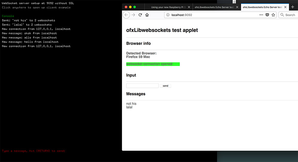
First I cloned it to my desktop computer to see if I the examples of it compiles there. It did and I was able to launch the example_server_echo.
Then I used scp to transfer ofxLibwebsockets to the Raspberry Pi.
scp -r ./ofxLibwebsockets pi@172.24.1.1:/home/pi/openFrameworks/addons/
Established a SSH connection, navigated to a directory with an example in it and tried to make it.
ssh pi@172.24.1.1
cd openFrameworks/addons/ofxLibwebsockets/example_server_echo
make
In about a minute I got a success message.
compiling done
to launch the application

cd bin
./example_server_echo

- or -

make RunRelease
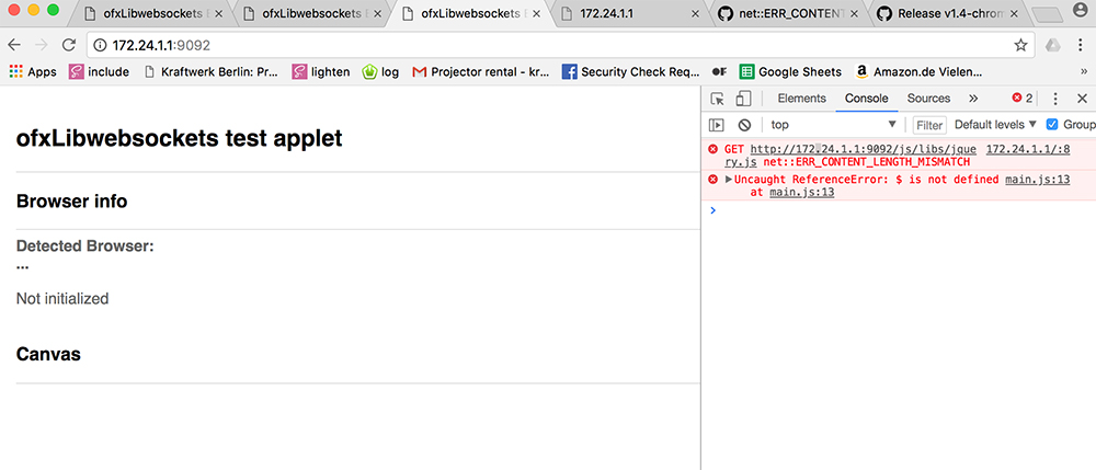
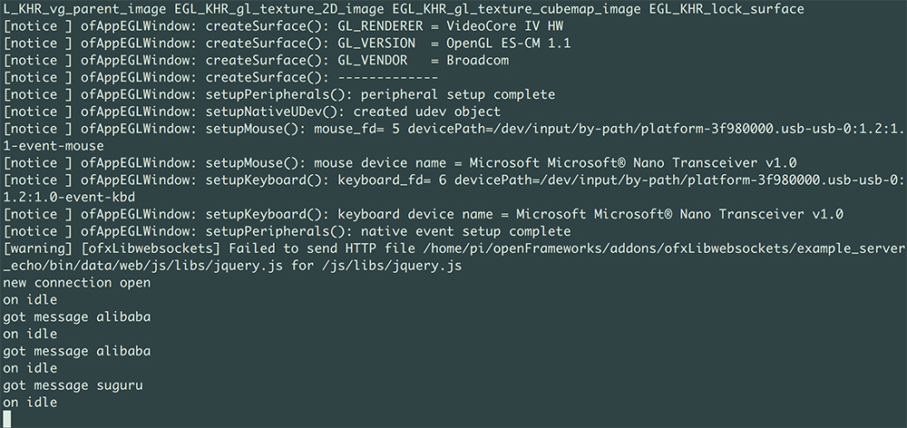
I tried to run it and open the web interface by using the IP address of the Raspberry Pi.
http://172.24.1.1:9092
The page opened, but for some reason jQuery refused to load. I was trying to replace the file with a newer version of jQuery, but no success. Somehow the current version has problems with serving files that size. It would have problems loading threejs as well.
Then I tried the JavaScript console of the browser and was able to send messages from the browser to the application running on the Raspberry Pi.
That worked. And sending messages of that size is what I need. What I decided to to was to serve the web interface using python.
I proceeded with building the webSocketsMapper openFrameworks application. First I wanted to get it so far that it compiles on my Mac and is set up for WebSockets connection as well as can receive messages.
Another thing I did to make the process easier, was to use the project on my computer as the git repository for project residing on the Raspberry Pi. I did this also because the ethernet connection did not work as expected and I could not access internet from the Pi, only my Mac computer over WiFi. This is how you can clone a git repository over SSH.
ssh://user@server:/GitRepos/myproject.git
Make sure that Remote Login in the sharing preferences of your Mac is turned on.
Later I solved the issue with my Raspberry Pi not being able to get a valid IP address from my Mac computer sharing a network connection over an ethernet cable. All I had to do was to open the /etc/network/interfaces configuration file and update the eth0 interface options.
sudo nano /etc/network/interfaces
...
auto eth0
allow-hotplug eth0
iface eth0 inet dhcp
This made it possible for the Raspberry Pi to be connected to the internet via the ethernet connection and be able to spawn a WiFi network at the same time. It would be also possible to bridge those, but not this time.
After many iterations of writing and testing code on my Mac and my Raspberry Pi, I managed to get it all working. One of the major issues was that the ofxLibwebsockets was conflicting with ofxJSON once I added ofxJSON to the C++ project in order to be able to parse incoming JSON messages via WebSockets. The fast solution to this was to not use ofxJSON and use XML instead.
The next problem was that the application on the Raspberry Pi was crashing at random points of time. It was related to ofxPiMapper functionality and I solved it by adding a few checks before selecting surfaces and moving vertices.
int surface = xml.getIntValue("surface");
int vertex = xml.getIntValue("vertex");
float x = xml.getFloatValue("x");
float y = xml.getFloatValue("y");

if(mapper.getSelectedVertex() != vertex){
    mapper.selectVertex(surface, vertex);
}

mapper.moveSelection(ofx::piMapper::Vec3(x, y, 0.0f));
Some time after this fix I still got a crash because of a segmentation fault. I am still looking for its origin.
Below you can see a video of the working solution. Notice how fast it is. Recently I also made a TCP remote control solution for ofxPiMapper. It seems that the WebSockets solution has a better latency than I monitored in raw TCP one.
The last remaining thing for this week is to get a message from the web interface to the board. I am going to add a button to the web interface and toggle the vibration motor whenever the button is pressed.
However it is not much different from reading input from a board using the serial connection. Here I add a link to Week 11 (Input Devices) where I describe how to connect a ATTiny board to the computer to control my projection mapping software.
Conclusions
Interfacing with electronics is very interesting and for most part it is just enough using serial communication to do so.
I was excited to get more experience with threejs to build the web-based projection mapping interface. There is still a lot to be done, but I managed to lay out the foundations for my future work regarding this.
There were a few problems related to WebSockets that I encountered along the way. I believe I already mentioned above, but it seems that it would make sense to use the web sockets C++ library directly in my projection mapping software code rather than trust outdated wrappers. Therefore on the application side I need plain web sockets functionality that does not include serving the web interface HTML files.