
Week 04
During the fourth week of the Fab Academy course we finally got to use some of the machines. We started out with examining the vinylcutter and were introduced to the way lasercutting happens at the Fab Lab Barcelona. The topic of the week was computer-controlled cutting.
The assignment for the fourth week consisted of two parts: a group assignment and an individual one. The group assignment was about characterizing the laser cutter and for the individual one everybody had to cut anything with the vinylcutter and design, lasercut and document a press-fit contstruction kit.
Group Assignment
This is our group: Dorota Orlof, Marta Bocos, Joris Navarro and me.
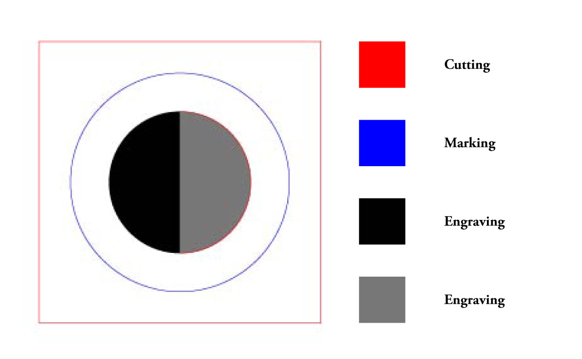
Dorota designed a simple test design which included lines to be cutted, marked and areas to be engraved. For engraving we went with an area that is black (0x000000 as color HEX code) and gray (0x888888 as color HEX code). You can see an image of the design below.
We created a Google Document for team documentation where we wrote down the lasercutter specifics. The model of the lasercutter we characterized is Trotec Speedy 400. It is forbidden to use any USB file transfer devices with the computer connected to the lasercutter to avoid computer virus infection risk. The Fab Lab Barcelona cloud is the recommended way of transfering files between our computers and the lasercutter computer.
There is Rhinoceros installed on the lasercutter computer. An important thing we noticed first was that it does not support SVG files. We had to save our test file again in either Adobe Illustrator (AI) or DXF (AutoCAD Drawing Exchange Format). Rhino on the lasercutter computer works in tandem with the Trotec Job Control application which is used to actually send jobs to the Trotec Speedy 400 lasercutter machine.
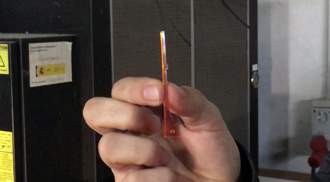
Before sending the files, one has to turn on and calibrate the machine. Due to a laser lens that was recently replaced, we had to use a custom calibration tool as the lens was not purchased from Trotec. It seemingly has the same parameters, but the resulting laser beam appears not to be focused in the same way as using the original lens. Below you can see the original calibration tool in action, but we later used a different one.
You can see the custom caliber in the image below.
When the laser is set up and we have chosen the X/Y origin point by using the push-button interface on the lasercutter itself, it was time to return to the computer screen, open the design in Rhino, go to File → Print and select Trotec Engraver as our printer. We set the scale to 1:1, which is recommended in most cases. Also, one should set the working area setting to window, that allows to move the working area relative to the design in Rhino.
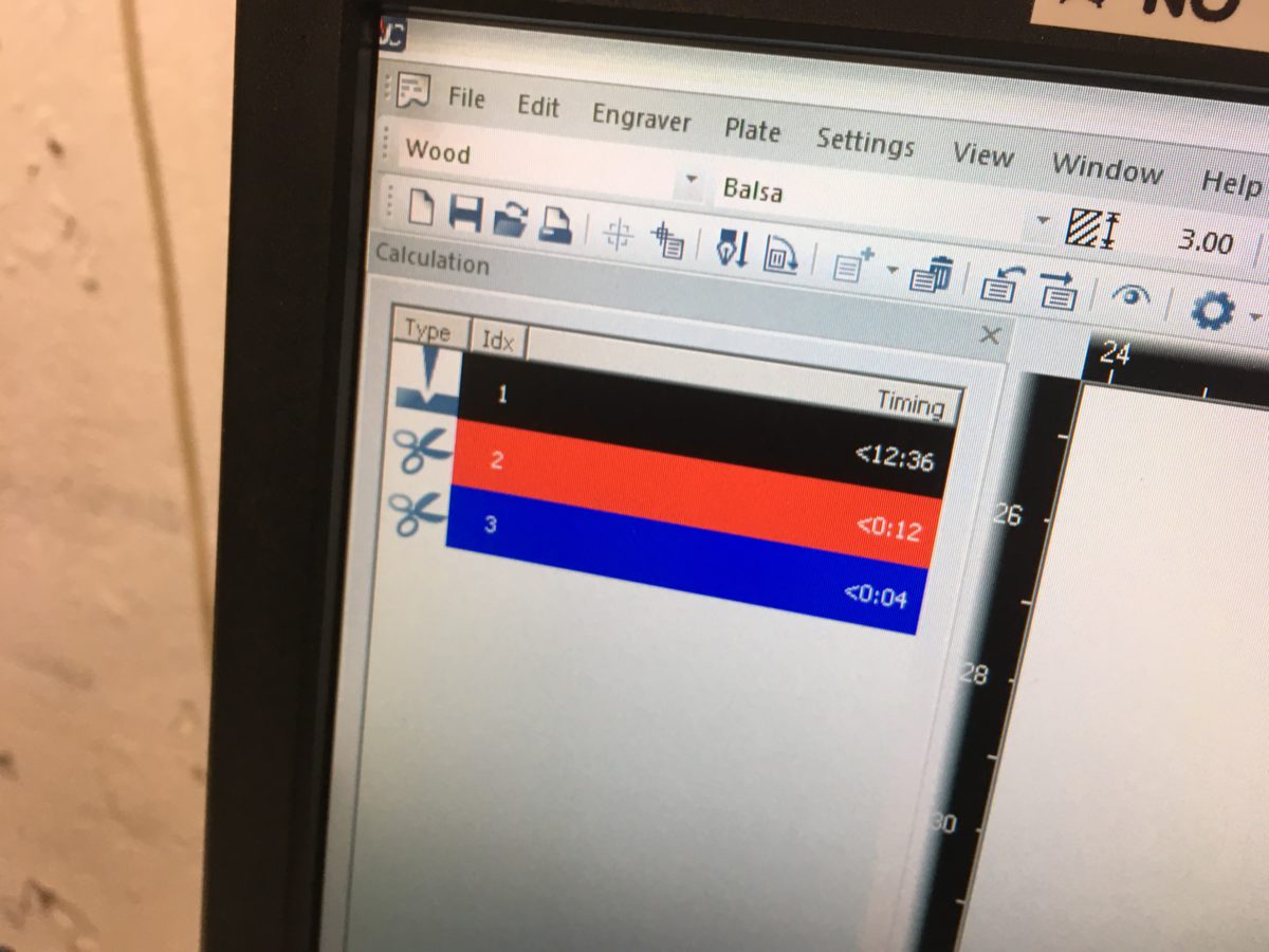
Setting up our job in Trotec JobControl software is the next step we have to do. Mapping colors of the design to specific lasercutter operations is essential. In the image below you can see that we mapped black to engraving, red and blue for two different types of cutting.
For each of the operations we have to specify additional parameters. There are three main parameters we have to play with when using the lasercutter.
- Power
- Speed
- Frequency
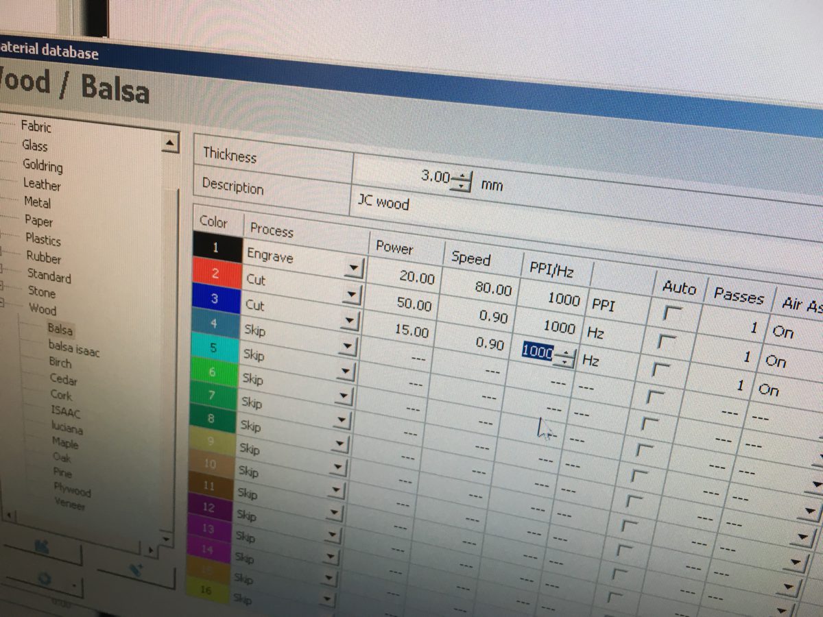
In the image below you can see how we specify the parameters for each of the color-mapped operations. This has to be done for every material separately. Each lab has presets, but it is recomended to experiment with values yourself for best performance and understanding.
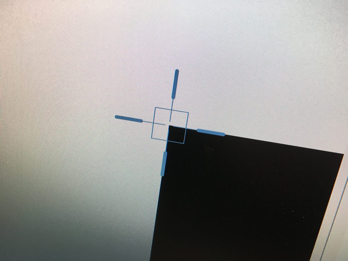
Before hitting the play icon to send the job to the lasercutter, it is a good idea to align the imported Rhino job to the lasercutter virtual origin placeholder. See how it looks like in the image below.
Send the job to the lasercutter by pressing the play button and change your body location to one that is closer to the lasercutter. It should be done not only because it is interesting to see how the lasercutter does its job, but because of safety. You should be present at the lasercutter while the job is running.
We tried to cut three different materials.
- Plywood
- Acrylics
- Cardboard
We spent most of the time cutting plywood as it was the first material and we wanted to get the laser settings close to perfection. Then we started to run out of time as the lab was being closed. You can see how we organized the test-cuts on a piece of plywood.
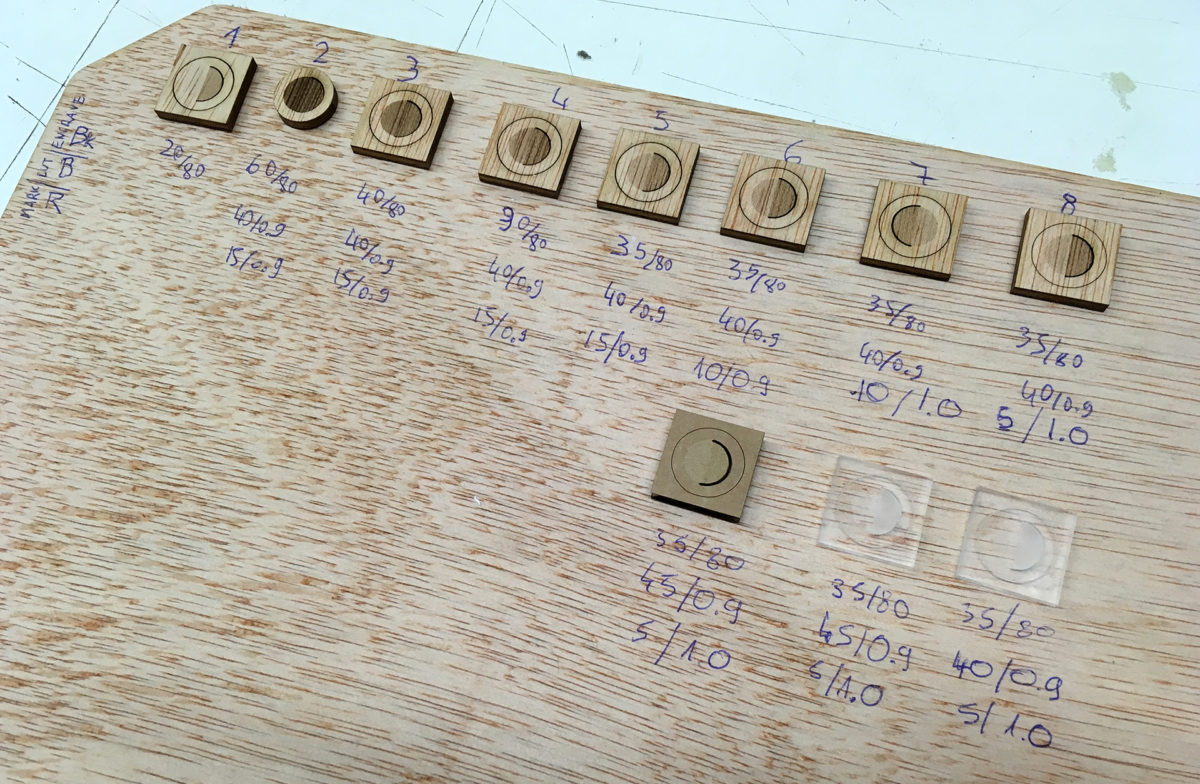
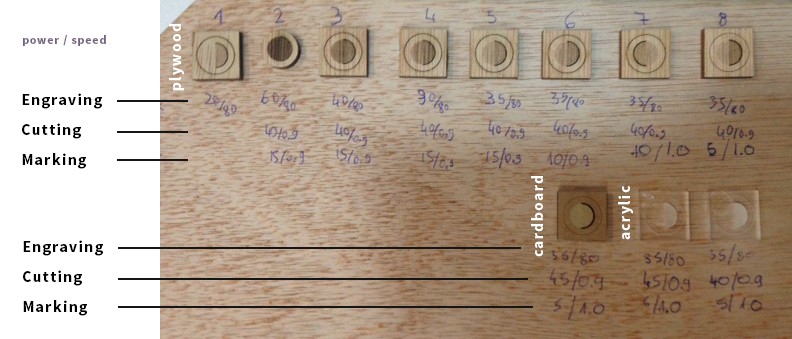
Under each of the test pieces you can see handwritten text, these are the parameters. The first line is engraving power and speed, the second is cutting power and speed, third is marking power and speed. It happened that the settings that we arrived at while cutting plywood, did work for an acrylics and cardboard sheet of the same thickness as well.
| Operation | Power | Speed |
|---|---|---|
| Engraving | 35 | 80 |
| Cutting | 40 | 0.9 |
| Marking | 5 | 1.0 |
We did increase the cutting power for acrylics as we thought one needs a bit too much force to break the piece out of the base sheet. 45% worked well.
Vinylcutting
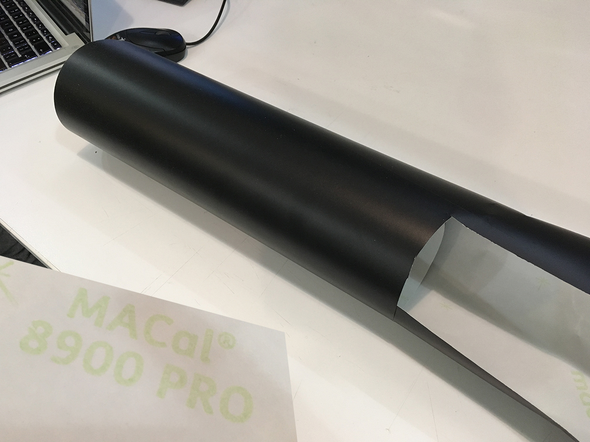
For me vinyl cutting started with a piece of leftover material (MACal ® 8900 PRO). The PRO extension made me feel good and expect a rather professional outcome. Thanks Coral for giving the leftover piece to me.
At Fab Lab Barcelona the CutStudio software is used to operate the Roland GX-24 Camm-1servo Desktop Sign Maker machine (vinyl cutter). The process starts with uploading your design file to the IAAC Fab Cloud or the data storage device of your choice.
The CutStudio supports .eps and.ai file formats. You have to make sure that you use the Adobe Illustrator 8 format for both, .eps and .ai. CutStudio does not let you to import later versions. I found that out by reading a topic on the Roland online forum and doing a few experiment cycles to find out which version actually works. After opening CutStudio, go to File / Import to import your design file.
Make sure you use Adobe Illustrator 8 format for both, .eps and .ai files.
Once the design is visible on the CutStudio canvas, one have to take it into account that the origin of the canvas is the left bottom corner.
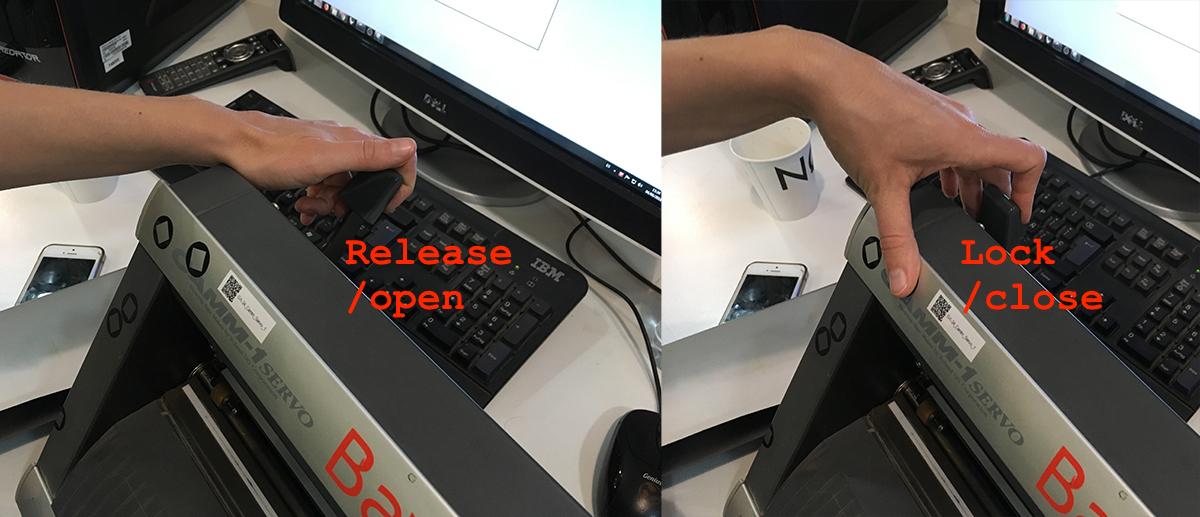
On the machine there are wheels that are there to hold the material down. You can lift them up by using a handle on the left back side of the machine.
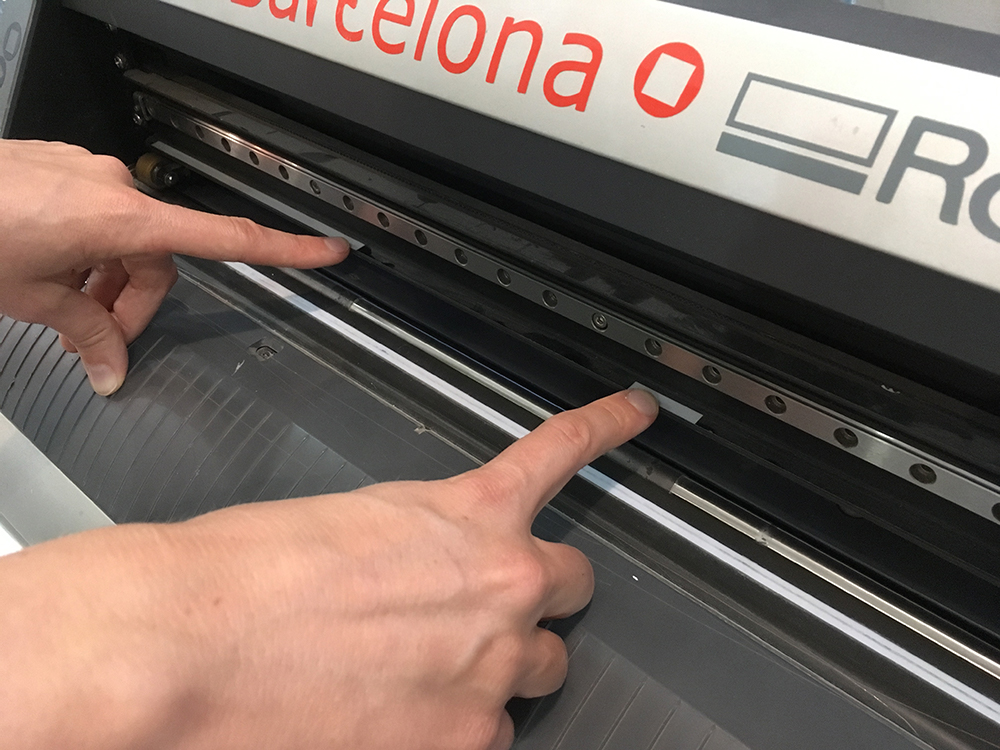
On the cutter axis there are white marks that show the areas where the wheels are OK to be positioned. Depending on the size of the material, the wheel position can be adjusted.
In my case the piece of the material is rather small. There are three options in the machine interface for calibrating it against the material.
- Roll. Machine will measure the width of the roll.
- Edge. Detects the edge of the material.
- Piece. Machine will measure the width and the lenght of the sheet.
In my case I went with the Piece option. The size of my sheet was 281x134mm.
And here another video from a different angle.
You should do a test cut before sending the job. Press (and hold a second or so) the Test button on the machine. It should cut a circle. You should be able to easily remove it by using your fingernails or a scalpel.
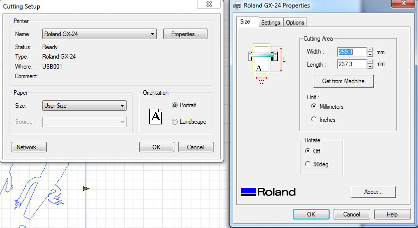
Back to CutStudio to send the job to the machine. Go to File / Cutting Setup, then Properties and use the Get from Machine button to get material dimensions from the machine that you just calibrated. Hit OK.
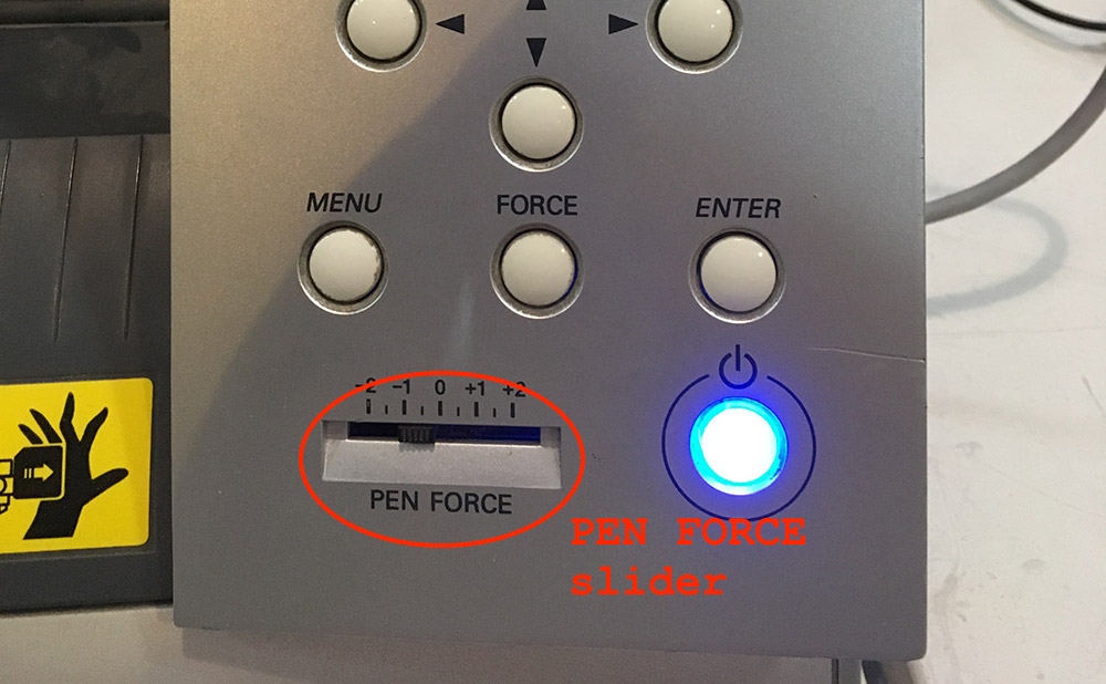
Use the arrow keys on the machine to get a better view. If the blade did not cut through, use the PEN FORCE slider to add a bit more force. In my case it took only one adjustment cycle until I was able to remove the test cut piece.
After doing the test cut, it is a good idea to reset the origin of the machine. That can be done by using the arrow buttons on the machine first to adjust the position of the blade (take into account that the origin of the design is left bottom corner) and use the Origin button (press and hold for a second) to set the origin.
Next, back to the CutStudio, go to File / Cutting to send your design to the machine. Enjoy!
Designing Press-Fit Kit
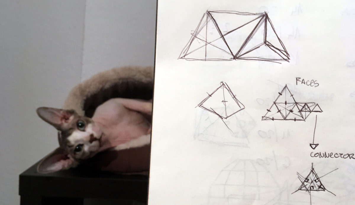
Since I had to prepare a projection mapping workshop for 20 participants and each of them was supposed to have a surface object, this task was a perfect match with my actual intentions. I started sketching and quickly decided that triangles are going to be the base primitives I will continue working on. Below you can see my sketch with a lazy cat in the background.
Since trying out different CAD software last week, I have had a few thoughtful moments where I was thinking about FreeCAD’s OpenSCAD integration. I have not used OpenSCAD for some time, I believe it is a powerful CAD tool and therefore I will chose it as my software of choice for this task.
I will design two main parts.
- Face Triangle
- Connector
The Face Triangle is going to form the faces of my triangle objects. It will have three tabs in the center of each edge for attaching a Connector. The Connector is going to be build around a triangle that one would get by connecting the center points of each edge of the Face Triangle.
In OpenSCAD I am going to start out with defining main variables for my design.
edgeLength = 100;
materialThickness = 4;
cutDepth = 5;
tolerance = 0.025;
It is a good idea to keep the OpenSCAD CheatSheet open. My goal is to create each part in its own file. As a result I will have two design files and one for the variables.
I had to remember a bit of trigonometry to calculate the essential variables for the main triangle and the connector design.
triangleHeight = edgeLength * sin(60);

// Distance from triangle center to one of its vertices
triangleRadius = triangleHeight / 3 * 2;

// Distance from origin to connector vertex
connectorRadius = triangleRadius / 4;

// Distance from origin to middle of edge of the connector
connectorRadius2 = connectorRadius * sin(60);
I defined two reusable modules, one for the face and another for connector cuts.
module cut(angle, radius){
    rotate([0, 0, angle])
    translate([0, radius])
    square([materialThickness, cutDepth * 2], true);
}

module face(verts, radius) {
    n = len(verts);
    angleStep = 360 / n;
    difference(){
        polygon(verts);
        for(i = [1:n]){
            angle = i * angleStep - angleStep / 2;
            cut(angle, radius);
        }
    }
}
All of that I placed in a config.scad file to be loaded from face.scad for the main face design and connector.scad for the connector design.
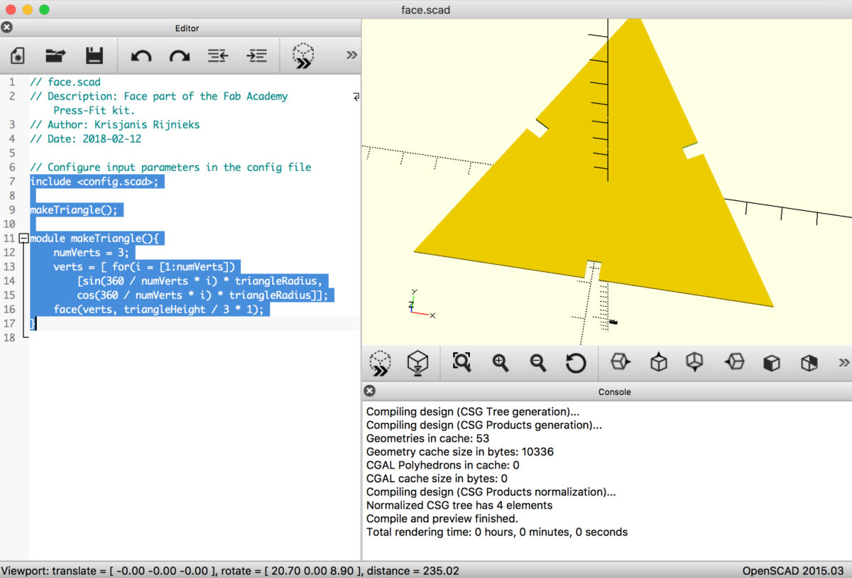
// face.scad
include <config.scad>;
makeTriangle();
module makeTriangle(){
    numVerts = 3;
    verts = [ for(i = [1:numVerts])
        [sin(360 / numVerts * i) * triangleRadius,
        cos(360 / numVerts * i) * triangleRadius]];
    face(verts, triangleHeight / 3 * 1);
}
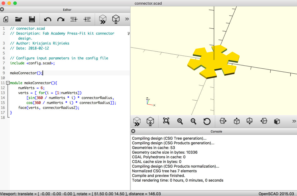
// connector.scad
include <config.scad>;
makeConnector();
module makeConnector(){
    numVerts = 6;
    verts = [ for(i = [1:numVerts])
        [sin(360 / numVerts * i) * connectorRadius,
        cos(360 / numVerts * i) * connectorRadius]];
    face(verts, connectorRadius2);
}
In order to export for lasercutting, I used File → Export → Export as DXF. You can find the full project source code on my Fab Academy Git Lab page.
Cutting the Press-Fit Kit
For cutting the press-fit kit I used the Trotec Speedy 400 lasercutting device. At the Fab Lab Barcelona one has to use the combination of Rhino and Trotec Job Control to get the job done.
Most importantly, one has to export DXF files from OpenSCAD. Once that is done, the resulting files have to be transferred to the computer connected to the lasercutter.
Create a new project in Rhino and import the files one-by-one. Select all and type Make2D to make shapes two-dimensional.
OpenSCAD does not connect the lines, use the Join command to close the polygons.
Select the shapes you want to cut and select the desired color of your lines in the panel to the right. Then Ctrl + P to open the printing dialog.
Set the size of the area you want to cut and position it by using the Window positioning option in Rhino print dialog. Click Print to send it to Trotec Job Control.
In Job Control make sure you are connected to the laser and positioned it where the top-left corner of your design should be. Use the red laser marker to move the cutter. Then drag and drop incoming print job so the top-left corner snaps to the cursor.
Before sending the job to the laser, make sure you have calibrated it and adjusted the material settings. For the material settings I used the following.
- Power: 80
- Speed: 0.75
- PPI: 1000 Hz
I used a 5mm thick plywood for my parts.
After 5 iterations I also managed to adjust the tolerance of the snap-fit parts. If you visit the file repository, you will see that OpenSCAD config file has integrated tolerance variable and it is set to -0.2. It is a negative value because the laser beam eats 0.1mm of the material when it cuts. To compensate, I move the negative snap walls 0.1mm more inwards.
module cut(angle, radius){
    rotate([0, 0, angle])
    translate([0, radius])
    #square([materialThickness + tolerance, cutDepth * 2], true);
}
Note the materialThickness + tolerance part. In the case of negative tolerance the width of the square being drawn there is actually smaller than materialThickness.
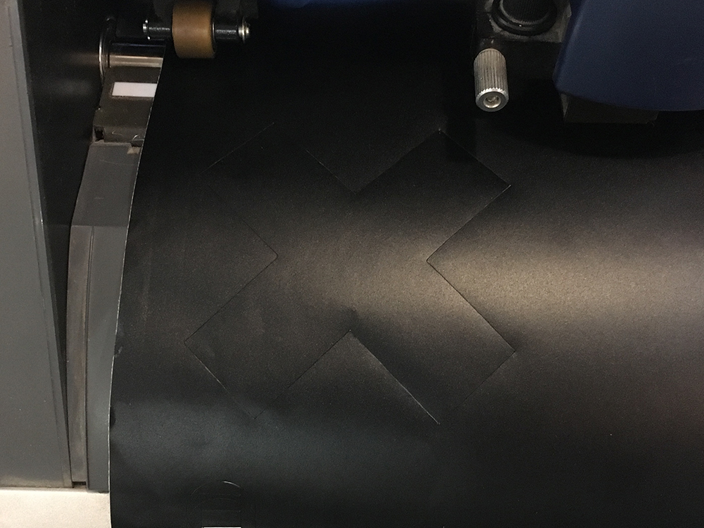
I cut 9 triangles and 16 connectors. Tried to make different abstract objects from the parts. You can see them in images below.
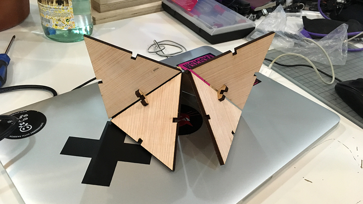
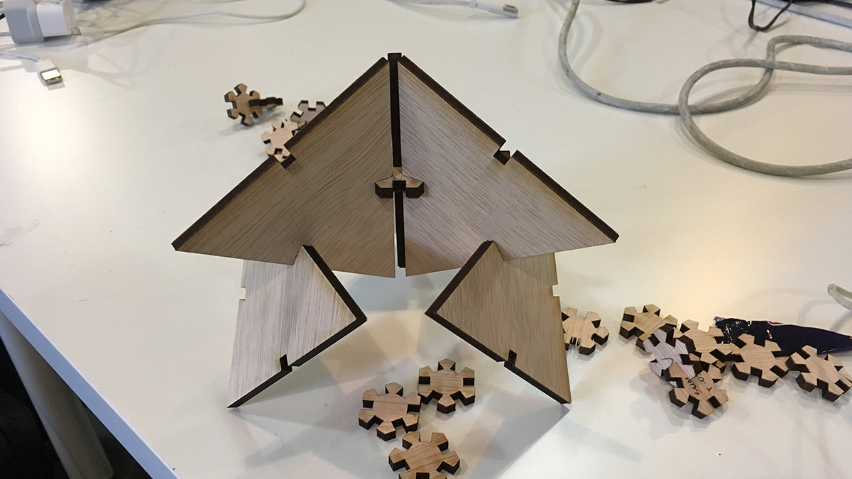
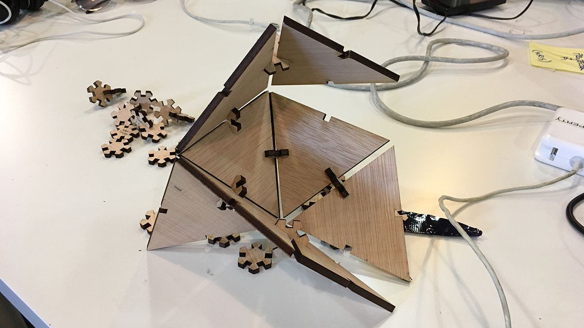
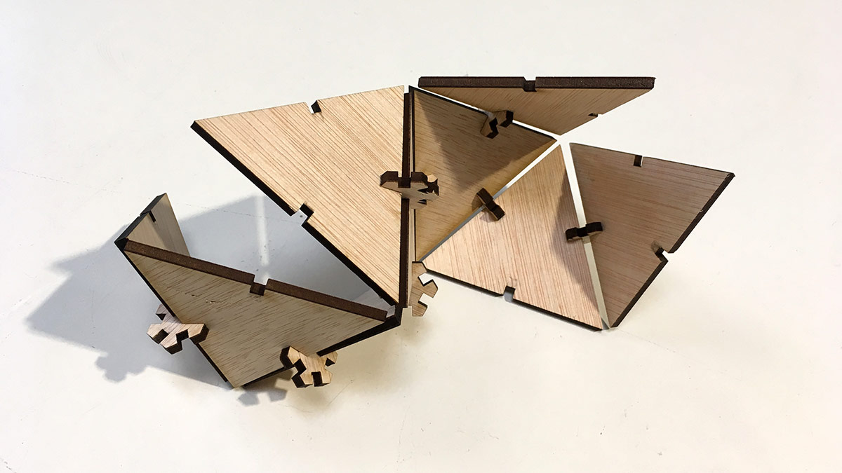
Furthermore I realized that I will use the kit for my final project to demonstrate projection mapping capabilities of my uMap device.
Conclusions
I have never used a vynilcutter before thus it was interesting, although I did not have too much time to spend for it. I have done lots of lasercuting in the past, but mostly with Epilog lasers, thus it was interesting to learn to handle Trotec.
All in all this week was not exactly what I was mostly interested in as for the course in general and its relation to my final project. I may use lasercutting to cut some parts for the electronics housing part, but I also want to keep things simple and I believe the less parts a thing has, the more durable and easier to maintain it is.
I had a hard time figuring out what would be my extatic interest during this week, thus I focused on getting a level deeper into OpenSCAD. The thing I designed is partly useful.