interface and application programming
.
lecture / slide: Fabacademy 2015 05.06D Lesson14: Interface and Application Programming MIT CBA Interface and Application Programming.
topics: languages, device interfaces, user interfaces, graphics, multimedia, math.
assignment: write an application that interfaces with an input &/or output device!.
experimentation: I was looking for a template code or something that would help me approach the idea of moving the deltabot in space and Arduino and Processing are my prefered tool in this case. I need to make and interface in Processing that will send out serial values that can be read in Arduino IDE to be translated into Servo positions. Also I gave a first go to using Firmata but I think I will stick to the serial communication due to it's easier use and more reliable connection. Basically I will use the computer mouse as an input to drive the machine and I reckon that building a delta robot is more than anything else about the correct interfacing. Here my intention of workflow: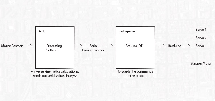 First tests: A simple interface based upon Processing Examples Sketches (Mouse 1D and Serial Write). Still running with Arduino UNO, the mouse movement along an axis translates into servo movements:
I put together a simple first version of a delta robot to understand the right movements. It still runs on the same sketch and basically just moving along the z axis due to the parallel movement:
Kinematics of a Deltabot are pretty complex and not easy to understand if your background is not necessarily mathematics or related fields:
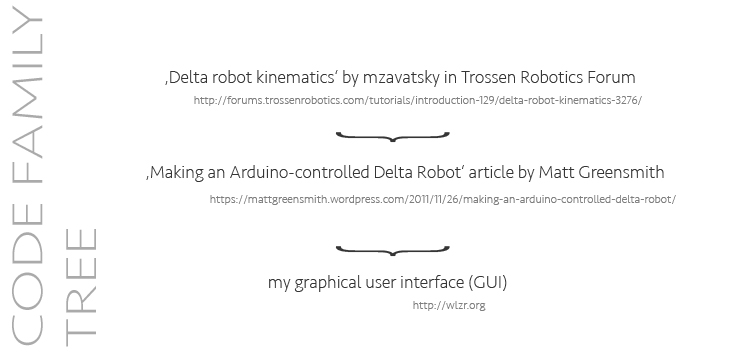
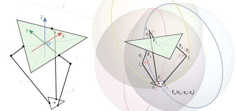 I found some articles that were dealing with the mathematical calculations of a deltabot and would work in Arduino/Processing eventually using serial communication. Matt Greensmith used the delta bot kinematic calculations from the Trossen Robotics Forum and added a controlP5 interface that works just perfectly! Just insert your dimensions, servo reaches, USB ports etc and you are ready to go! See here the "family tree" to understand where things were coming from (simplified):
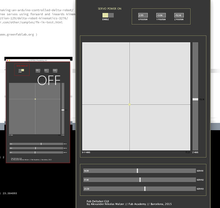
 Seeing here the slightly adapted GUI by Matt Greensmith to controll my first machine! It is initially based upon a sketch from Principia Labs that I can't locate anymore in the internet but it uses controlP5 library to have a graphical user interface (GUI) in Processing and calculating in the background the calculations from the Trossen Robotics Forum. At the end, Processing sends out x,y,z Values via serialWrite and Arduino is listening via serialRead and with the servo.h library translating to Servo positions. It works!
See here screenshots of my "final" graphical user interface, it changes some details when turned on and off and connects all the values within the script. You can either change specific positions in x,y,z (top right, just click it and type it in) and the script will calculate necessary servo movements. Second option: drive x,y via a 2D screen + z slider or third, controll each servo on its own:
 GUI in use, see the values in the monitor sent out by Processing in the back:
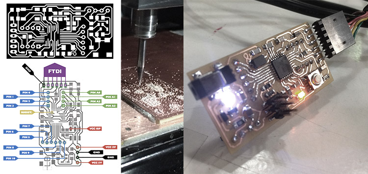
Board: Since I will not be able to use an Arduino Board for my final project I made an Barduino board. Find the schematics for Eagle in the links below and make sure to have a 1/100th inch Millbit ready and select it in FabModules. For the means of speed I chose to run first with 1/64th inch millbit using offset -1 for cleaning the board and then run a second iteration with the 1/100th inch millbit with only one offset. This will save time, just make sure to only reset the z when changing the millbit. Once the board is milled - as always - make a list, get some tape and collect the parts according to the schematics. Solder them to the board and programme it with the FabISP board that we have made earlier (not shown in the photo). Connect also the FTDI cable and burn the bootloader.
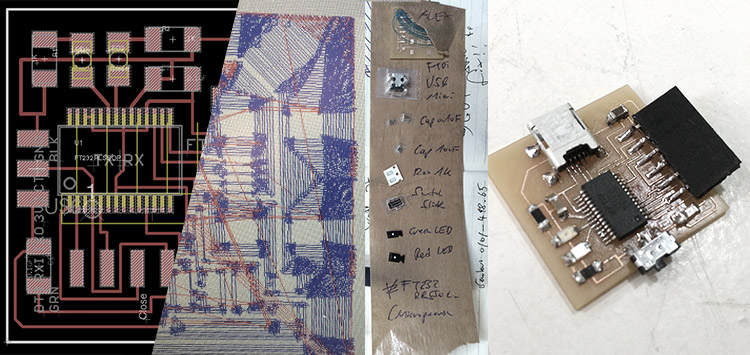
 Instead of using the FTDI cable we also made the modified version for the FTDI chip that has been modified by our friend and colleague Yani in the FabLab Barcelona. It saves you 18 Dollars on the cable and you can programm any board with a Mini USB cable (Let's say for the future all you need is the FabISP to burn the bootloader and the FTDI board + two USB Mini cables).
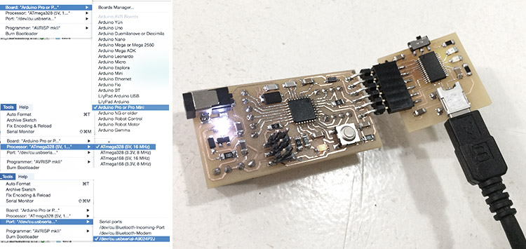
 Connecting both boards to your computer, opening Arduino Software. Check your USB port and it's ready to be programmed as a Arduino Pro or Pro Mini with ATmega328 (5V and 16Mhz). The pins are done via through-hole pins on the bottom, just make sure to connect accordingly to the pin out diagram.
 Since my Barduino wouldn't run even if I tried fixing it with Ferdi several times I was happy enough to be able to use the one from my friend Milena. I programmed it via Arduino IDE as a Arduino Pro / Pro Mini. And now - finally - the GUI can communicate to Barduino! No Servos are connected yet but PIN13, one of the LED on the board is turning on and off when power for the servos are enabled (part of the script):
First tests with the new setup (Barduino + GUI). It works!
Transparent machines love the darkness (the machine was hanging at this point to take nice pictures of it, thus shaky):
.
files: Files wlzr Fab Academy '15 // w15.
bookmarks / links: Arduino Simple Servo Control tutorial Arduino - Interfacing Arduino and Processing (Firmata) Sparkfun Connecting Arduino to Processing NYU Physical Computing - Controlling a Servo Motor from a Processing Program Sparkfun - Serial Communication Matt Greensmith Making an Arduino-controlled Delta Robot Matt Greensmith Making an Arduino-controlled Delta Robot controlp5 a GUI (graphical user interface library for Processing.
global review: Fabacademy 2015 05.13B Review14: Interface and Application Programming-

Any content on these pages by Alexander Nikolas Walzeris licensed under a Creative Commons
Attribution-NonCommercial-ShareAlike 4.0 International License