Electronics Design

The assignment this week is to make a design for an electronics board and then make it with the Roland Modela mill. For the design, we used Eagle. The nice thing about Eagle, is that it lets you work from schematic level, all the way to board design and trace files that can be fed into the Modela.
Eagle is not a straightforward piece of software. For one, you need to use the right libraries for the components, because package designs can vary quite a bit as I found out. Luckily, Eagle comes with many libraries pre-installed (it then becomes a challenge to choose the one you need). Suppliers like Sparkfun have a lot of their own libraries as well.
There is also a Fablab library, that we could use for this assignment.
Here you can see the schematic view in Eagle. This is where you determine the components you ant to use and how they are connected.
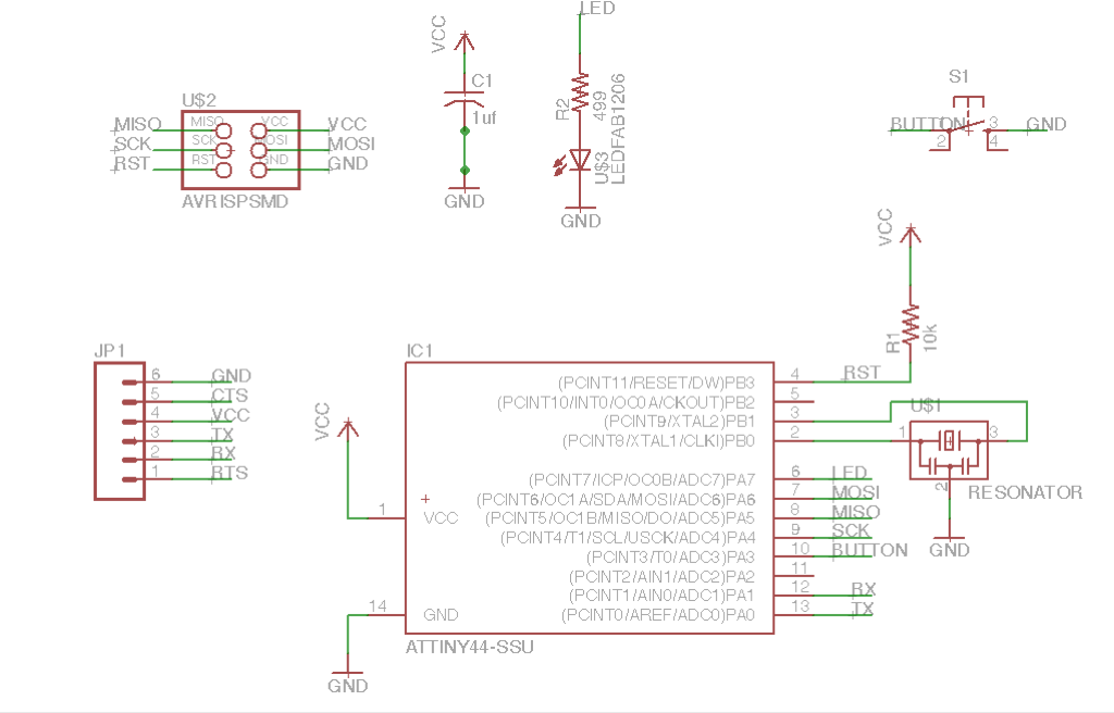
One of the nice features is that you can label connections, so you can work with individual components, or blocks of components. This helps to keep an overview of what you are designing. This is an example of how a button has two labels, that point towards the ground of the schematic and another connection (in this case one of the pins of the ATTiny44): 
A schematic always has a board view linked to it in Eagle. It is important to keep both files open when you are working in them, because otherwise, Eagle can't update changes. Using ERC and DRC, Eagle can tell where there are issues with your design so you can fix them. This is the board view:

After the design is finished, I exported the image with only the traces (and other elements that needed to remain on the PCB after milling) to a PNG file with suffix '_top'. I then opened this file in GIMP and resized the canvas by adding 20px to the width and height. This gives the image a border so that the traces do not end up too close to the edge of the board.
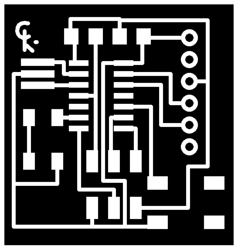
I then duplicated this file and gave it the suffix '_cut'. By filling all surfaces in GIMP I ended up with an image that has the outer cut trace (and holes, I should have added, as I realized later..) to cut the milled board out from the source material.

I then fed the PNG's into the mill to mill and cut the board:


When stuffing the board, the resonator was a little tricky, because it is a tiny object with 3 traces that need to be soldered. The trick I used, was to places solder on the trace on the board, lie the resonator on top of it and heating the solder with the heat gun. At some point, the resonator just sank into the solder.
Another problem I ran into, was that I forgot to tell the Roland Modela to mill holes for the FTDI cable so I had to drill them by hand. This was not too big of a problem, because the traces showed me where the holes had to go and the component that needed to go in there is pretty strong so it can withstand a little wiggling.
Here is the finished board: