Week 12 - Output Devices
Assignment: add an output device to a microcontroller board you've designed and program it to do something
CAD Work
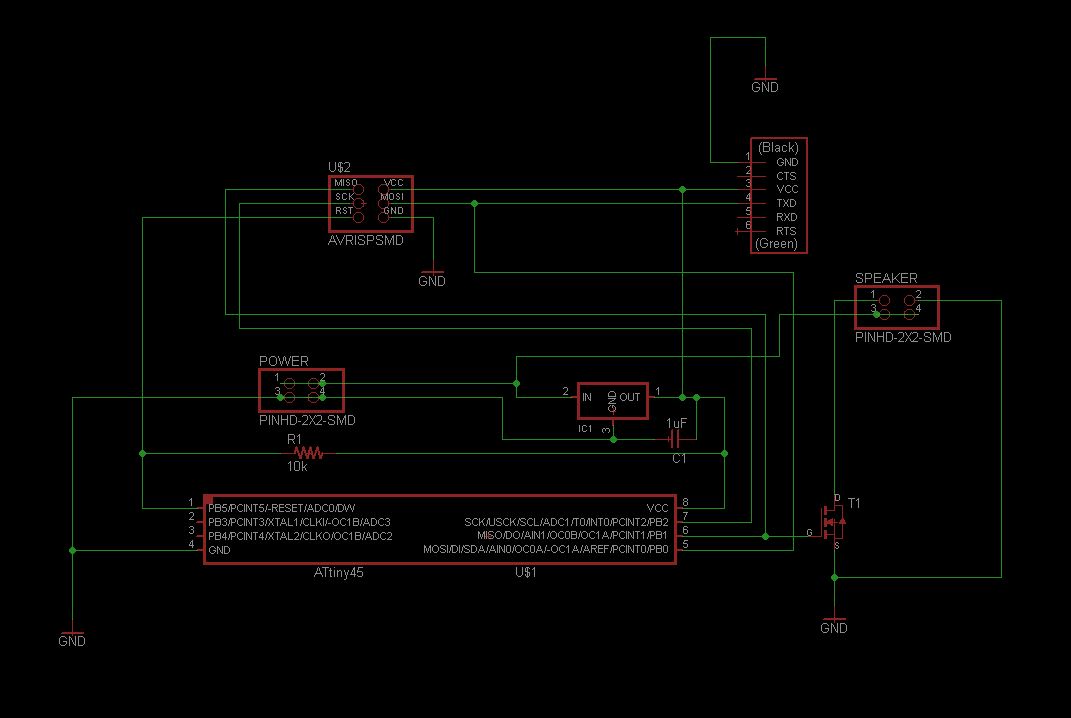
I decided to make a board to connect to a speaker. I looked at hello.speker.45 and saw that I could base my design on that but I wanted to add a ftdi port to be able to send commands from the computer directly to the board. I used eagle to design the circuit and PCB.

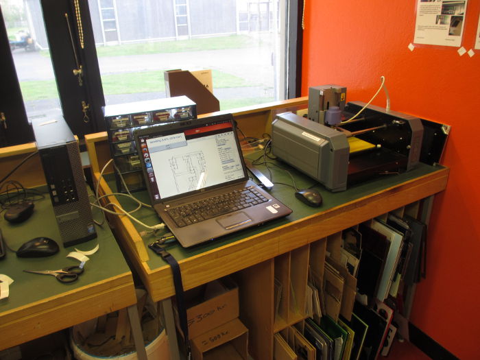
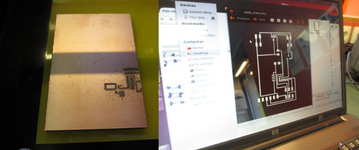
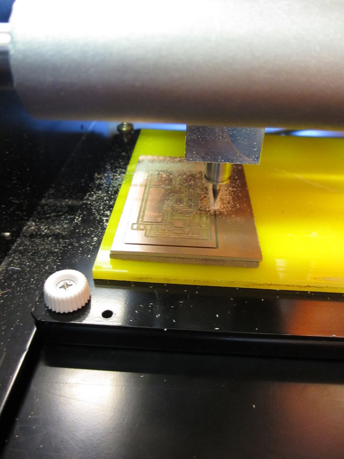
milling the pcb
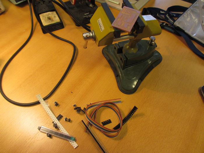
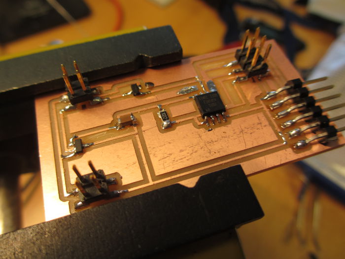
stuffing the board
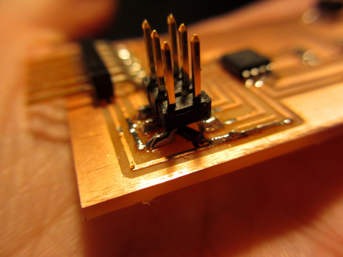
Next i solder the components in there place
I had to fix the pads for the regulator since the milling bit left some parts
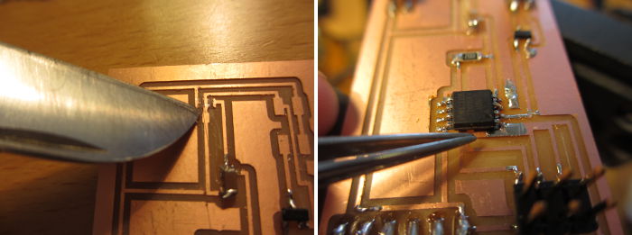
After I had had put everything in place I noticed on the photo that the IC had been put in wrong so I rotated it. When connecting to the computer I got a power surge error. When looking in to it I saw that there was a short were the milling had not been able to remove the copper
At this point I decided to make the hello.speaker.45 board just to try out the programing. I tried the example program and it worked good.
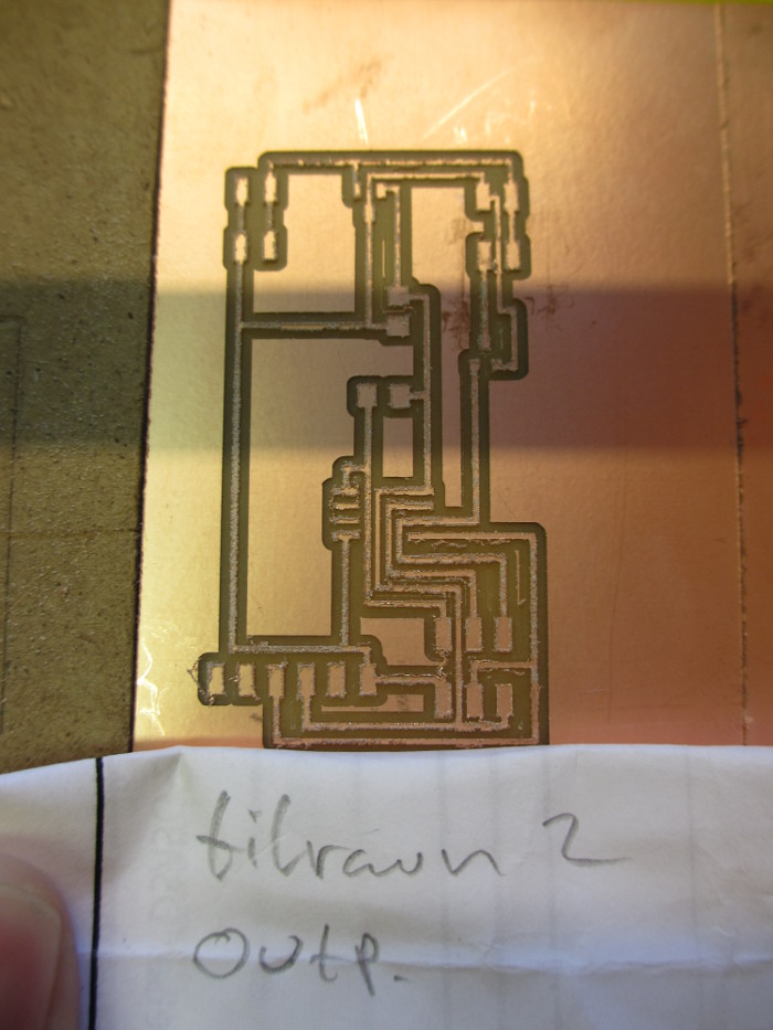
Second try
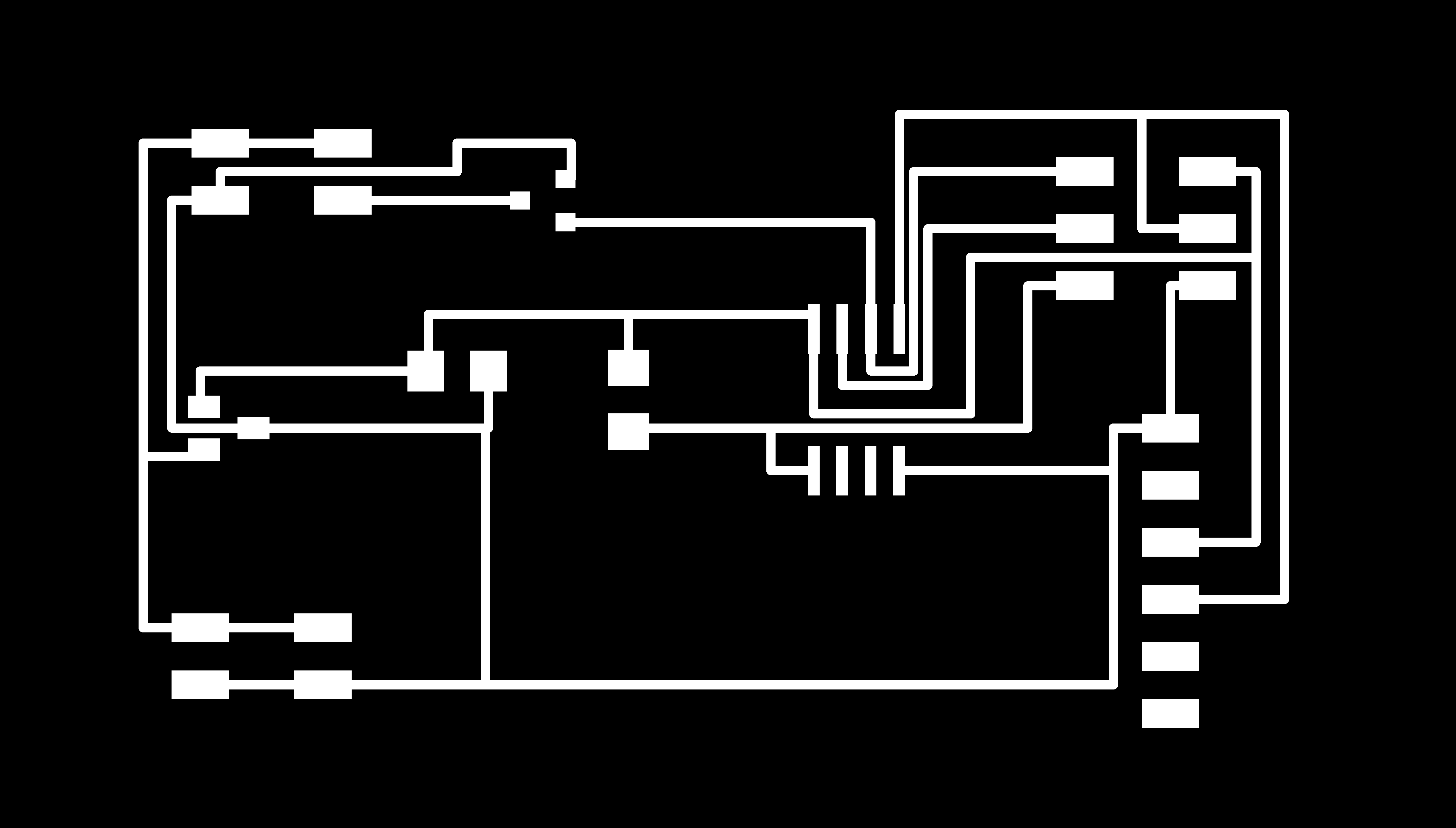
I had some time to try doing the board again. I changed the design files now so the milling bit can fit between the traces. I also fixed the pads for the regulator in Gimp2.
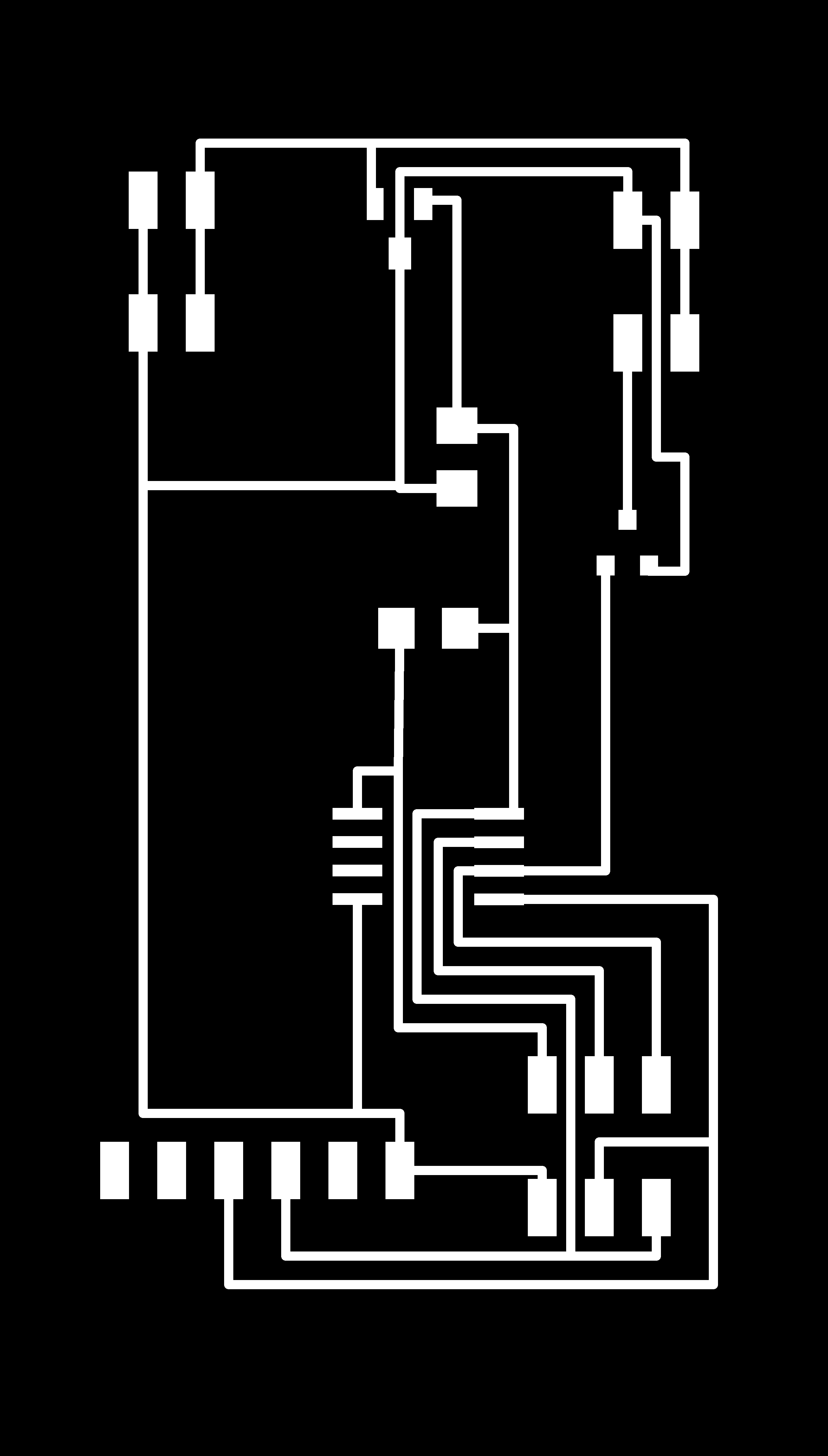 Improved design
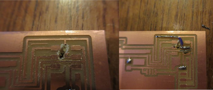 I had small problem when I was about to cut the frame, the milling bit when straight into the board and when I looked at what was going on I saw that the dpi value was at 72 dpi not 1800 dpi. I restarted the machine and did it again now at 1800dpi. The damage on the board was easy to fix with a wire.
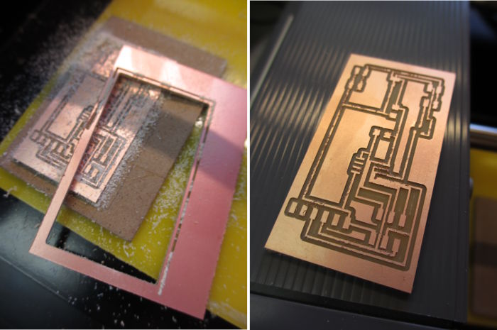
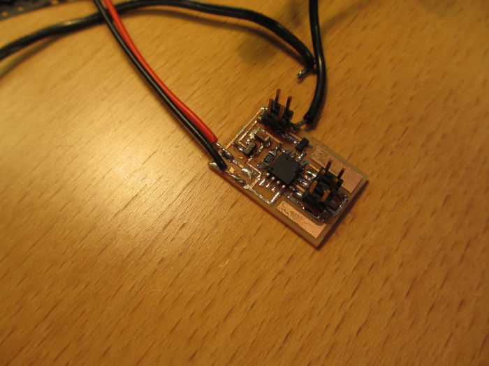
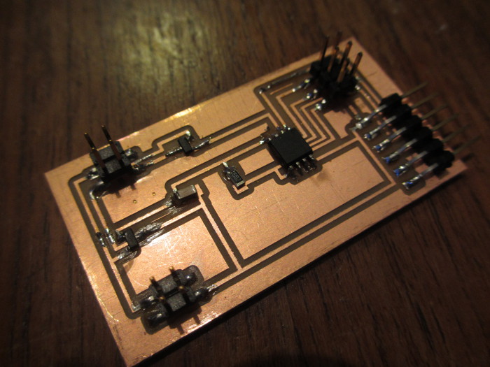 The final result look good the board was a bit bigger than expected.