
Final Project
Part One Planning
Part Two Electronics and Programming I
Part ThreeThe Mechanism
Part Four Final Assembly in Solidworks
Part Five3D Printing the Components to make the Machine
Part SixElectronics II
Part SevenThe Files
Planning
The aim for my final project is to make a new tool for creation ...
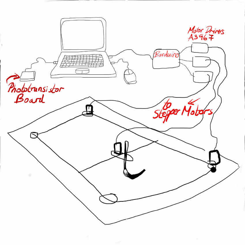
A live painting machine which can create large scale paintings at the move of a mouse with z-axis control.
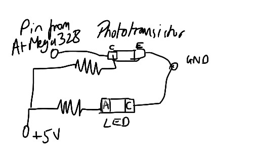
The focus of the project is to create a real time controlled machine. The z-axis will be controlled with a touchless sensor using synchrounous detection and a phototransistor, as experimented in this page.
Beginning
Where do I start?! I ask my classmate Jani, who is also making a machine,
"I always start with the electronics."
So I did...
Electronics and Programming- looking into the possibilities
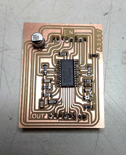
I have been comparing the Easy motor driver created by Evil Mad Scientist for the Eggbot and the fab-in-a-box motor driver - they are the same, apart from the Easy Motor driver has a 5V voltage regulator for logic input on the board
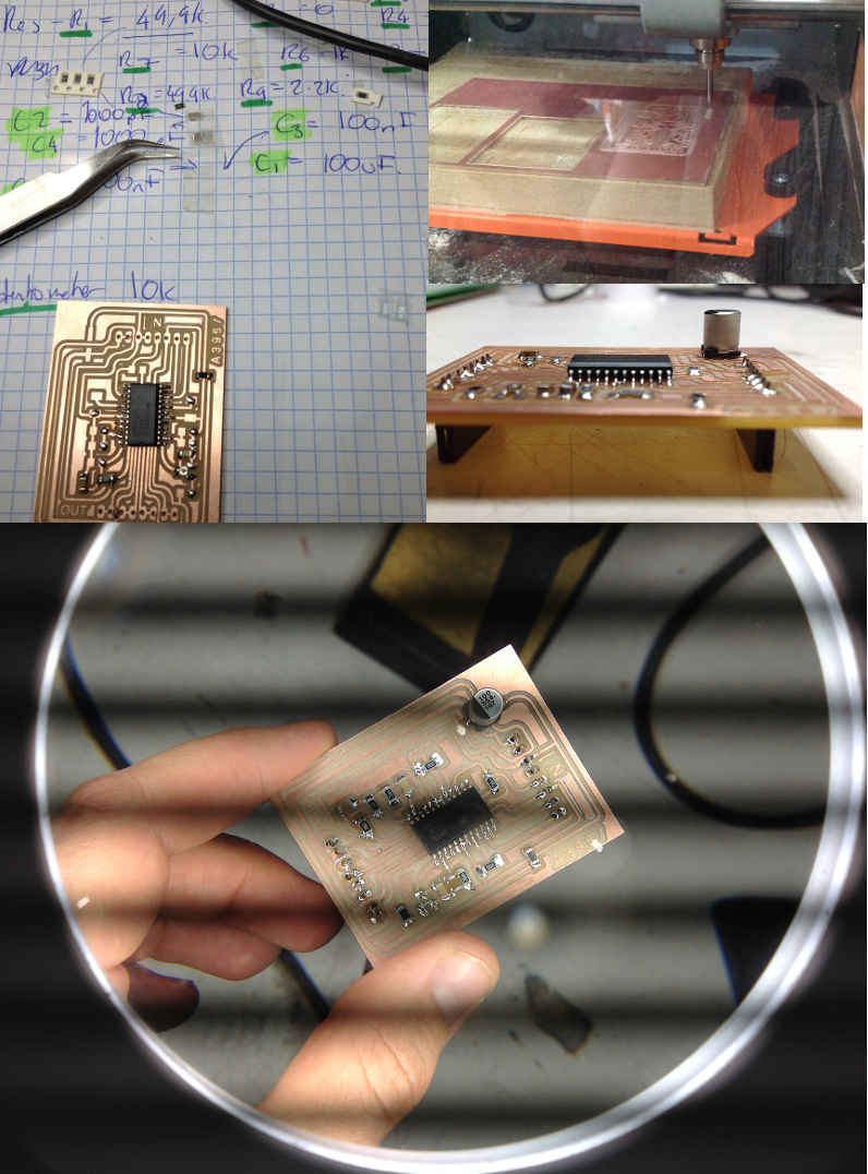
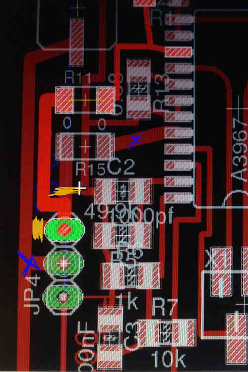
So I have taken the Fab in a box Schematic and Board and modified the headers. I also changed the component values, thanks to our electronics maestro Jani's calculations.
First iteration of the board is complete, milled and stuffed. Slight problem with the fine detailed milling between the headers (as some wires need to pass between pins) that was not picked up by the webserver fabmodules- despite having changed wire widths in eagle. In the future I will use my downloaded fabmodules which seems to pick these up better.
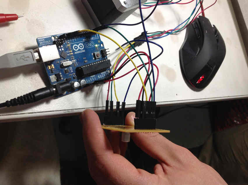
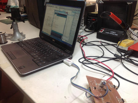
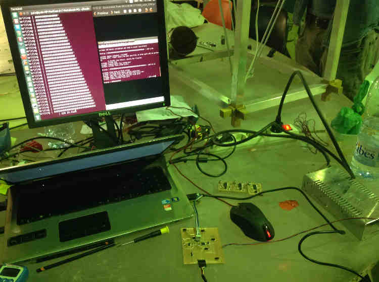
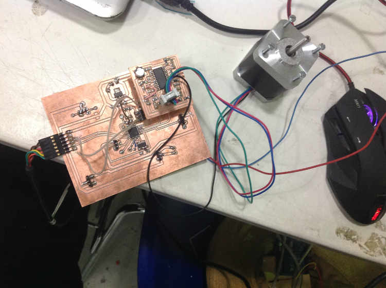
After manually cutting the connections with a small knife, I stuffed the board, connected it to an Arduino to test it using a steppper motor following this tutorial and arduino test program.....AND It works!
Next step is to look at the controller board. Originally I envisioned using the Barduino, but the Fab in a box designed a special Fabnet board which I am looking into also. Both use the ATMEGA88. First thing was to distinguish the difference between an ATMEGA-88 vs ATMEGA-328. I found this useful chart: 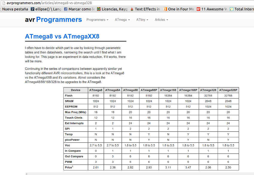
Basically pins out are the same, AtMEGA 328p just has better specs.
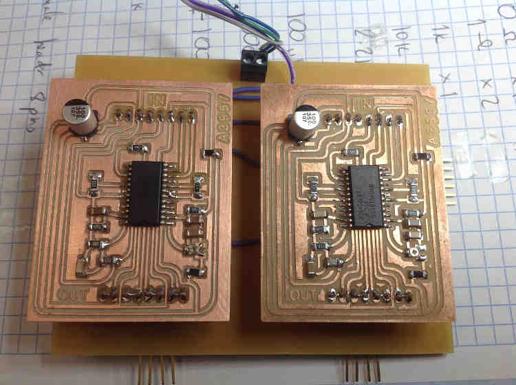
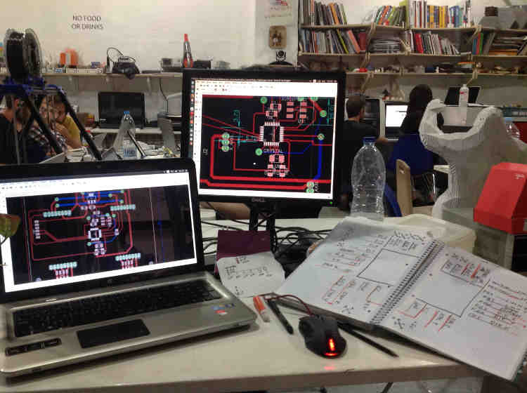
I have been working with Jani, I made the motor drivers and he made a controller board based on Barduino, which could fit under the driver boards.
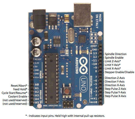
We based the controller board on the barduino, and we used the pin out map from grbl for arduino uno.
I have been looking at the ways to send movements to the motor drivers. I was looking into a ring buffer, a software data buffer, to send information to the motor drivers. I found a ring buffer for arduino. However since I will be using a coreXY system, and due to lack of time, I decided to use grbl for CoreXY.
There are four changes to make to grbl to get it to work with coreXY, pulled from here: Grbl for corexy. However after changing the files the grbl was not working. I realised I was replacing files written in c with files in c++. Not sure if this was why. Regular grbl worked fine but to use it with my corexy cnc system I need a specialized gcode interpretor.
I found a hex code for grbl corexy using avrdude and linux terminal. I download the hexfile to my Desktop, access the Desktop on the terminal then execute:
sudo avrdude -c usbtiny -P usb -p m328p -U flash:w:corexy.hex:i
First came "error changing fuses". I had not connected 12V power supply... now it loads.
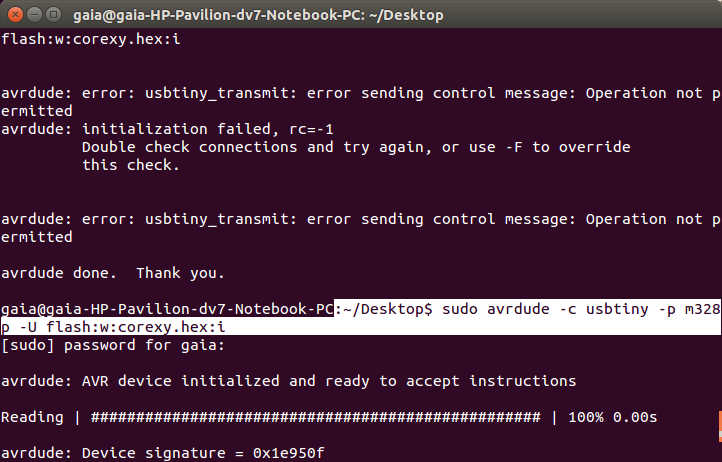
However after trying to burn the hex file without power it changed the fuses. I discovered this after trying to use a processing sketch to send gcode, gcntrl gui.
Error disabling serialEvent() for /dev/ttyUSB0 null ... because gnd to pwer had fallen off. Now everything runs codes etc everything BUT the motors!
So I bootloaded the arduinoISP again... using the Fab ISP and Arduino IDE.
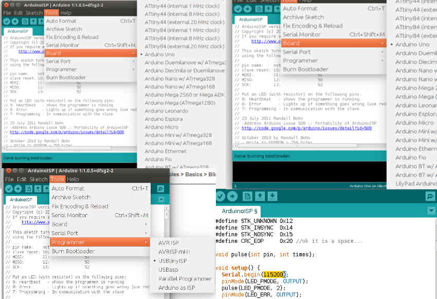
Then I load the hex file for corexy grbl again. First I test it with the Universal Gcode sender. Motors move a bit when initially connected but I have no control. After troubleshooting I realise I had set the baud rate to 9600 instead of 115200... baud rate checked this time set at 115200. Then with the gctrl processing sketch! And it works, I know this because both motors move when just moving in x or y direction !
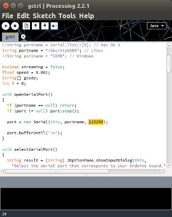
So I have got grbl installed on the controller board, and I can talk to grbl ... through usb cable using serial communication with a ftdi chip.
I use a processing sketch gctrl to serial communicate with grbl, which I had implemented which tells the motors where to move.
Motor juttering. so made new motor driver, eliminated problem.
The Mechanism
In the original design of corexy Bot of the Cloth, strings are used. I have decided to use belts instead, GT2pulley belts which are 6mm in width with a period of 2mm (same used for the reprap machines). I want the design to have detachable components so that it can be installed in any location
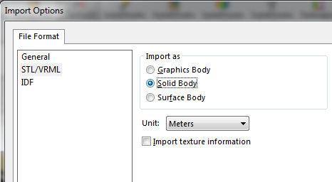
My program of choice is Solidworks. I learnt a useful tip to import stl files into Solidworks. In the import window, once selected stl, click on the options button.
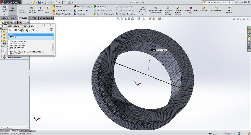
First I design a motor holder, using a Nema17 stl model from thingiverse to aid the design process.
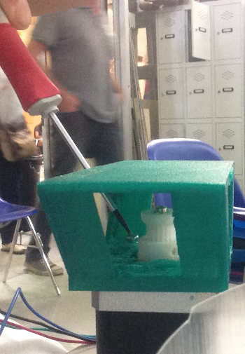
I asked people in the lab for a mechanism to move something up and down. Francesca told me about a cam pulley. It seems like such a simple effective idea. After researching a bit about cam pulleys I managed to recreate one in Solidworks!
How can I attach the brush to the cam pulley, first idea:
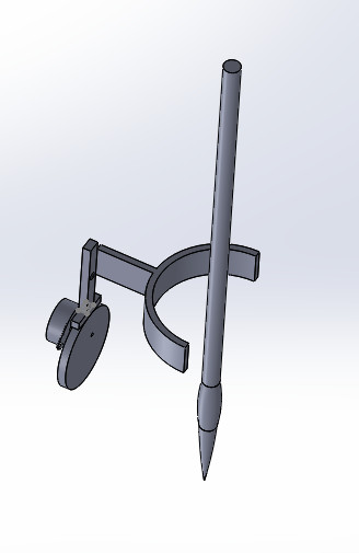
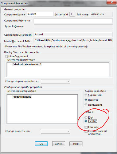
Selecting Component Properties of the subassembly inside an assembly gives the option for it to be flexible, that way I can see how my paintbrush will move up and down on the canvas.
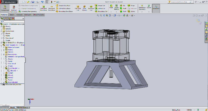
Incredibly logically, we can calculate the mass of the object and find the assembly's centre of mass. I weighed the paintbrush and so input its mass. For the 3D printed parts I just input the density of the PLA material I was using and Solidworks calculated the rest!
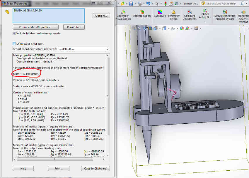
Since the centre of mass appears at the unipolar, I intend to put the rod as close as possible. I am concerned that the centre of mass is above the platform.
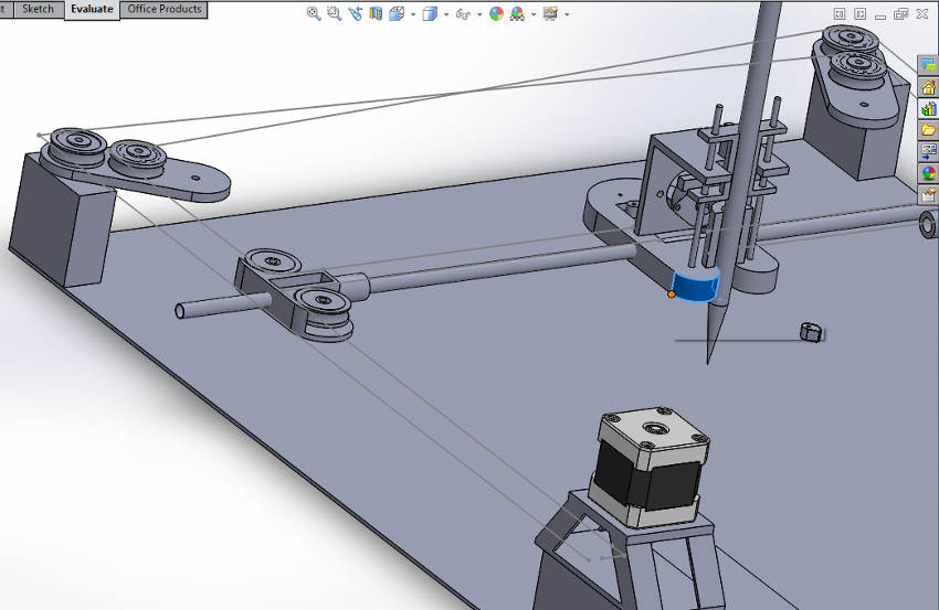
Then I get on mating all my components and subassemblies.
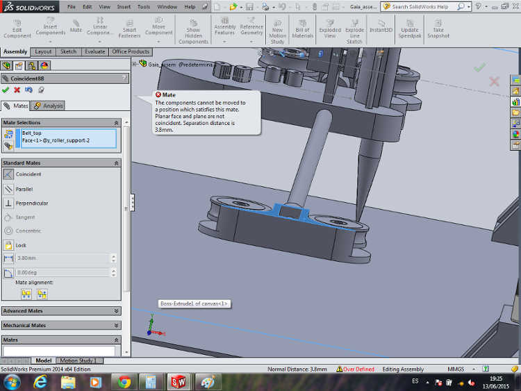
However, when I sketched out where the top of the XY belts fall (see above, grey line)... I have an alignment challenge!
The paintbrush I wanted to use, has a height of 4.5cm which means the whole assembly needs to be brought up... Unless, I find way to attach the belts to the Shuttle brush lower down. My only worry is that the shuttle could topple being top heavy. Otherwise I will have to lower my ambitions and choose a smaller brush.
Mechanism- Alignment Solution
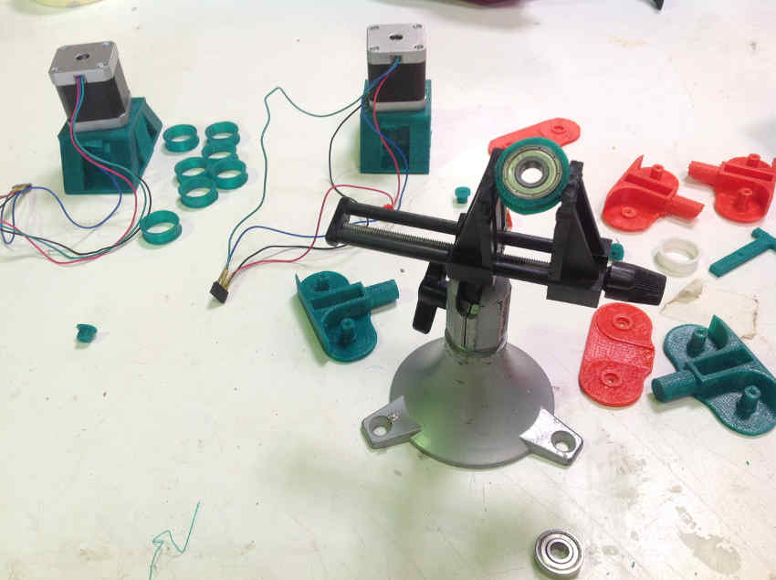
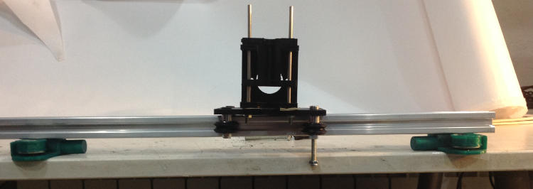
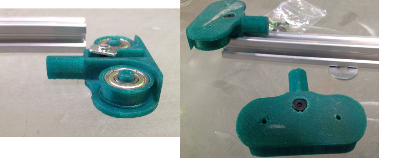
After approaching my instructor, Ferdi with my predicament he suggested to use a V-railing with wheels, I can attach the painting shuttle to the platform. I have 3D printed a base to test how it fits. I am now working on integrating this new part into the assembly.
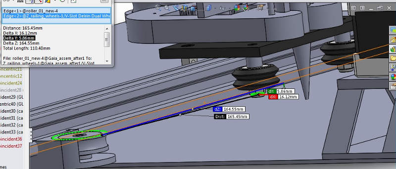
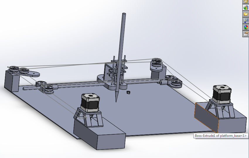
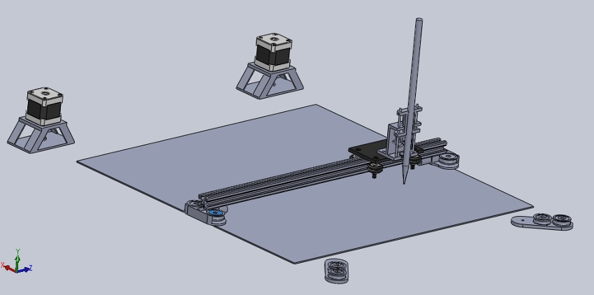
The final assembly:
I can use exocentres to adjust the width perfectly to the railing.
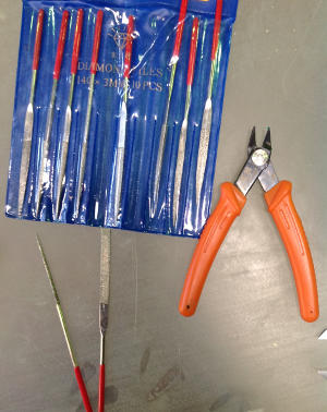
3D Printing the components of the machine
I recommend these tools when 3D printing. Very useful, to be able to sand inside small holes.
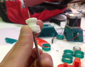
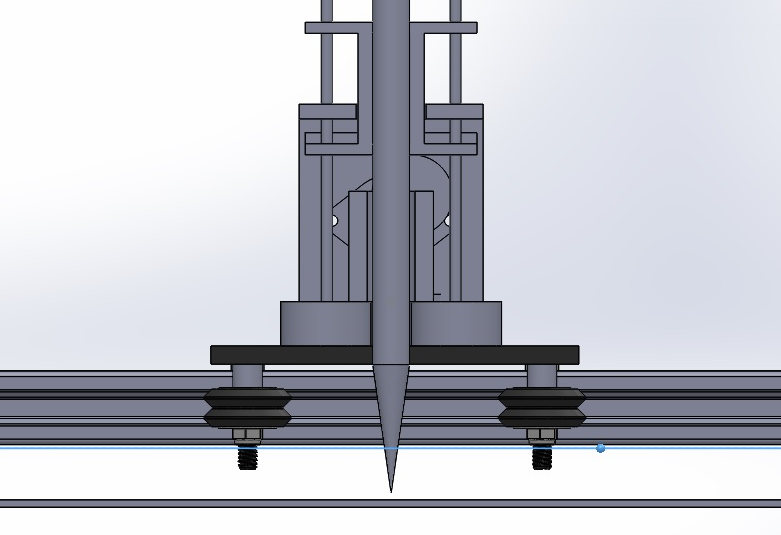
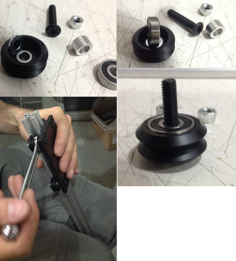
The Screws- Putting the Mechanism together
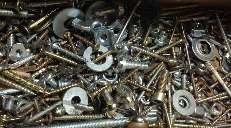
Next was to get the right screws and nuts, but I need to modify the screws so they do not interfer with the mechanism. As you can see above these screws are far too long and will not allow the shuttle to move around the canvas. I had not forseen this in my original design, so I have to modify the 3D printed pieces I have made. Next time I will remember to include screws, buffers etc. in the final assembly.
I realise the tension of the belts is very important. I also adjust the height of the top extreme pulleys with buffers, to ensure belts do not rub against each other where they cross.
I ask a friend to test out the mechanism manually:
Electronics- XYZ Drivers
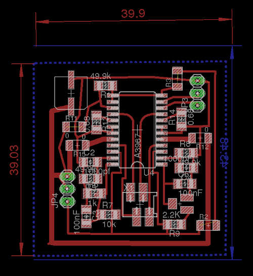
Meanwhile I have been starting to adapt the motor driver boards to include a Z axis. Eagle's free software version, has a max. board size of 100 x 80 cm. Therefore each motor driver board has to be reduced to fit 3 axis XYZ onto the controller board, so I squish everything in.
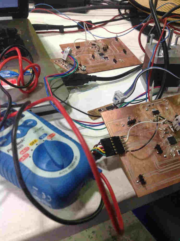
I milled the boards....and stuffed them.
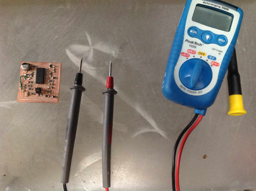
Testing the drivers and realised I made a mistake in my design. The multimeter, strangely measures 10V across the 5V wire on motor driver board. I test how much voltage is coming out the pin on the controller board, by putting the voltmeter pins on GND and +5V. It measures 5V correctly.
I looked at the schematic and compare it to my first iteration of the motor driver board, going pin by pin, I realise the Enable and 12 V pin are connected which is incorrect!
Great, now I just need to debug the boards and try again.
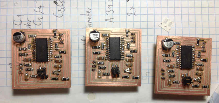
I continue troubleshooting the motor driver boards with an arduino, 2 out of 3 works:
- works well
- moves, but juttering
- doesnt move at all
I discover I had forgotten to solder one side of a resistor, now it stopped juddering and works fine . The board that didn't work at all had a mistaken connection between the Enable and 5v. Now all three motor driver boards work correctly.
Always allow enough time for troubleshooting for electronics, even if your first design iteration worked.
I test the motor driver with the unipolar motor which will be the Z- axis movement with paintbrush to vary in thickness.
I have found with bipolar and unipolar motors they are confusingly naming the coils sometimes coils A and B or 1 and 2. The Nema17 we have Coil 1 which has 1A and 1B and Coil 2, 2A and 2B.
I could not find a trustworthy indication on the internet for the unipolar so I used the multimeter to measure which wires gave a higher resistance. I found the red and yellow connected then the black and brown.
The driver is connected to an arduino in this following clip.
Not as smooth as I would like but functions!
Electronics- The Controller Board
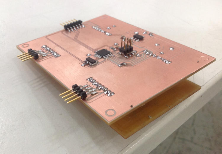
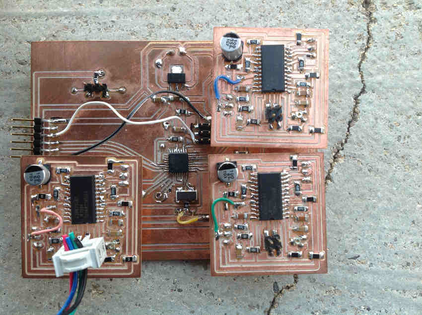
I have designed a controller board based on the board made earlier, this time to connect three motor drivers and a phototransistor board with 5V, GND and a pin from the ATmega328p. Eventually this will control the z movement.
Soldering the ATMega328p was challenging. I used flux to soak the footprint, then used very small amounts of solder, if two legs did stick together, then I use the soldering iron to spread the solder along the wires until they separate.
I manage to bootload the controller board with the Arduino IDE, and download the hex file, however nothing happens when I connect it with the motors and send it gcode.... I check voltages on controller board pin out. All seems ok. I check connections, also seem ok.
I make the control board again, hoping this time it will work. Same problem!
While troubleshooting Ferdi advised to make it work with the simplest programs first, so I try uploading a simple Arduino sketch for one motor. Still nothing. So I test the pins to attach to the motor driver boards. Only the z-axis gets 5V to the motor driver. The others are faulty.
I hope you can learn from my mistakes- I certainly have
The biggest mistake of all...
I learnt an important lesson while troubleshooting my controller board. NEVER test with a multimeter while connected to a computer. You can create a short circuit and destroy your computer. That is what happened to me. I had 12 V power supply connected to the controller board, and usb to my laptop. I accidentally touched the 12V and 5V pins. Needless to say, the laptop is no longer usable. My computer doctor said, multiple boards have been burnt, all around the usb connection point.
BUT...
This isn't over. I will have my painting machine.
My files
Finished WorksThe mechanism assembly in Solidworks
Motor driver board for XY controller board- 1st iteration
XY controller board
Smaller motor driver board- 2nd iteration
Works in Progress
XYZ controller board
The phototransistor board, schematic and board