
Input Devices
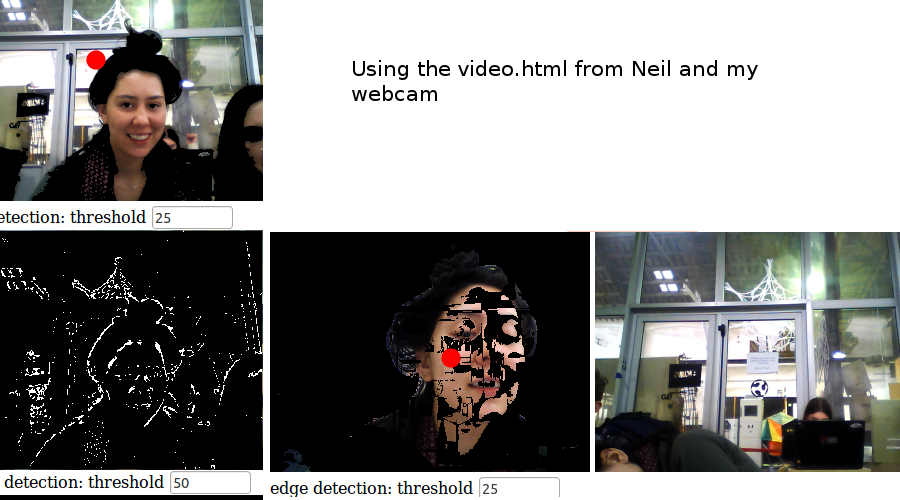
I selected two sensors to make from the class Input Devices page... an incredible resources for different inputs from magnetic fields to video.
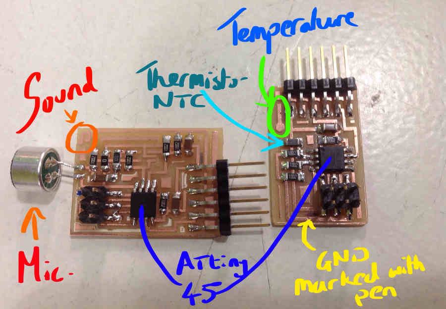
I first chose to make two of Neil's input boards:
- Sound sensor with microphone
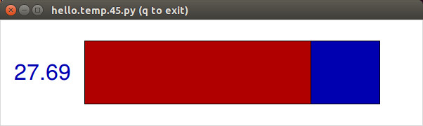
- Temperature sensor with NTC thermistor
Then I will design my own input board.
Roland machine using fab modules.
Computer boots in Linux. NOTE- switch on Roland after comp is on.. Then in the terminal:
fabport - links roland machine to comp. Then
fab - launches Fab GUI
Pick Process as Roland MDX for our machine and touch view on the Roland.
BEFORE MOVING TO Xmin Ymin - Ensure all settings including z depth are correct. I did not and I broke one too many mills!.... mmmmmm
Programming the Input Devices
- Download python on linux ( use readme file to configure and make)
- Make sure ground is connected correctly with Fab ISP and FTDI cable, to begine with FTDI cable is only used for power to the new board.
TIP: I like to mark with a pen where my grounds should be connected - Make folder with .make .c and .py files within.
- Access the folder in terminal
e.g.
cd ~/Desktop/input_mic - Program the sensor board
sudo make -f hello.mic.45.make program-usbtiny NOTE change commands for
your files
- Download Tkinter for python
sudo apt-get install python-tk - If successful you can disconnect FabISP with sensor board
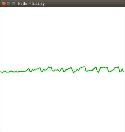
- Run Python file.
python hello.load.45.py /dev/ttyUSB0
Note to determine which tty your USB is connected to... unplug and plug the usb and run dmesg
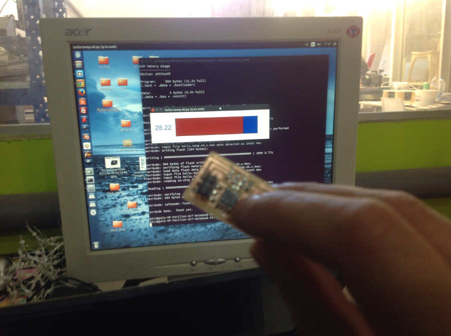
Then I repeated the yellow steps for the temperature board.
.
My own Design
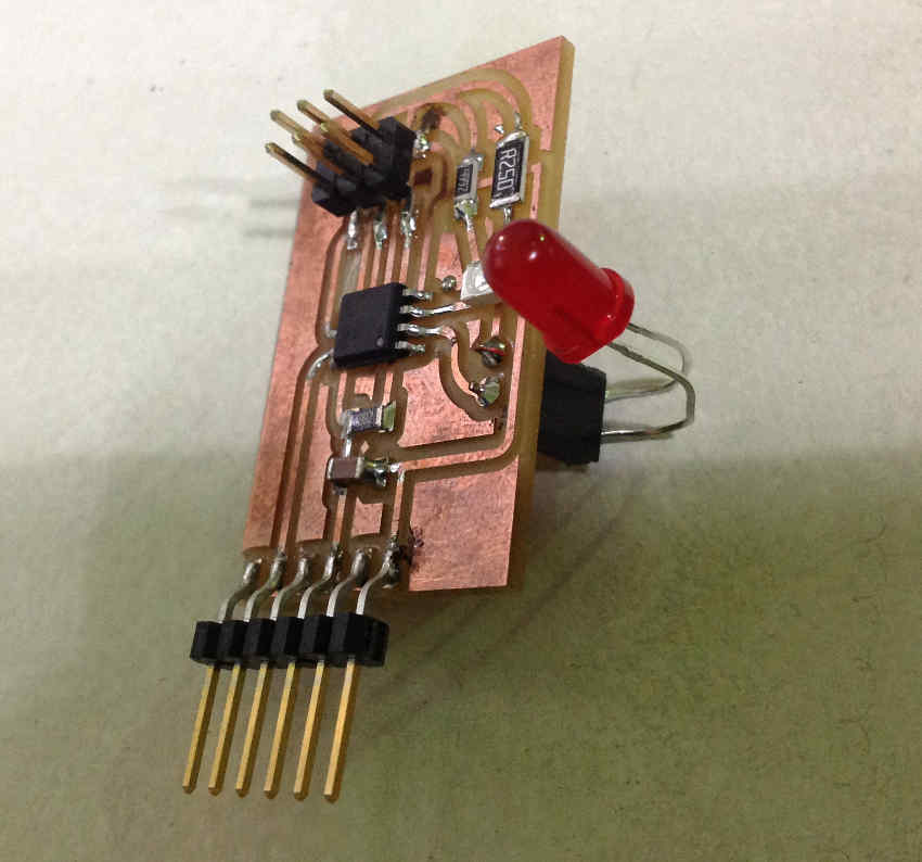
Synchronous Detection Phototransistor Board with Interchangeable LED
I want to make an experiment to see which colour LED works best with the phototransistor so I redesign the board to accomodate a female connector header to allow me to change the LED.
I check the datasheets of the LEDs I want to use, and calculate the correct resistor.
After experimenting with white, blue, green and red LEDs, I found the Red Led to be the most effective!
Get my files here