Electronics Production
How to Make One's own Printed Circuit Board
Printed Circuit Boards (PCB) are good for prototyping and are more environmentally friendly than Chemically Etched Circuit Boards. The alternative chemically etched circuit board are better for making larger quantities by sending off .png files to a local board house (they deal with the nasty chemicals) such as Euro circuits .
This week I am going to make my very own Fab ISP , which later I will go on to program!
Techniques I will use:
- Milling
- Soldering
I. Milling a PCB- I will need:
- One PCB template trace- I use Fab ISP Valentin , which can plug directly into the USB port
- One Milling Machine with drill bits 1/64 for the trace and 1/32 for the cut- I will use Roland Modela
- FR1 Circuit Board- copper sheets laminated onto a non-conductive substrate
- Double-sided tape
The vinyl board will be milled, according to the circuit template I downloaded. I will use Fab Modules to convert the .png template to a .rml files for the milling machine. I will use double-sided tape to fix the board down so that it will not move during milling.
Using Fab Modules for Milling:
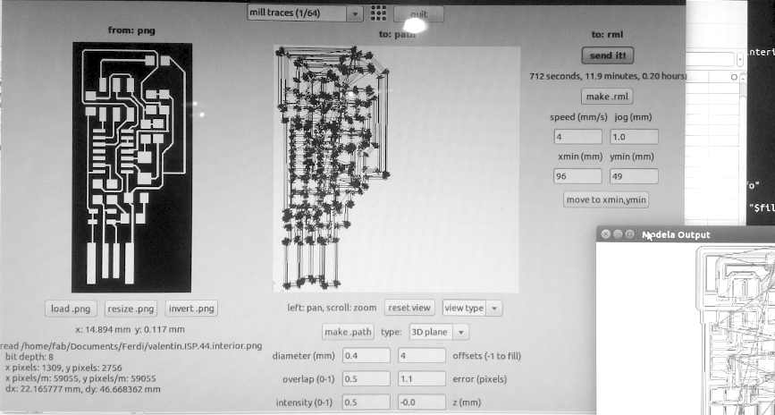
First do an outline trace of what will be milled.
- In Fab Modules select output mode to traces
- Change the drillbit of milling machine to 1/64 in View mode with max Z up, so that the drill bit arrives up to the front.
- In Fab Modules, set XY zero-position, xmin/ ymin (bottom left corner of outline)
- Click Move to xmin ymin
- On milling machine, set Z zero-position by pressing z-down button. When it gets close to the board press intermittently until drillbit punctures board. Then press Z-up button once or twice
- In Fab Modules, Upload .png
- Set z = -0.0, offset = 1.1
- Click make .path
- Click make .rml
- Click send it!
- Keep finger over View button on milling machine in case it messes up as is begins the trace
N.B. If it cuts the board (instead of tracing) there is a problem!
Next repeat steps 6 to 11, for the circuit board trace. I had to repeat the circuit trace because the first time the drill began to miss the board. Second time everything was milled correctly.
Then to cut the board, change drillbit to 1/32 (again with drillbit up and to the front- V. IMPORTANT!)
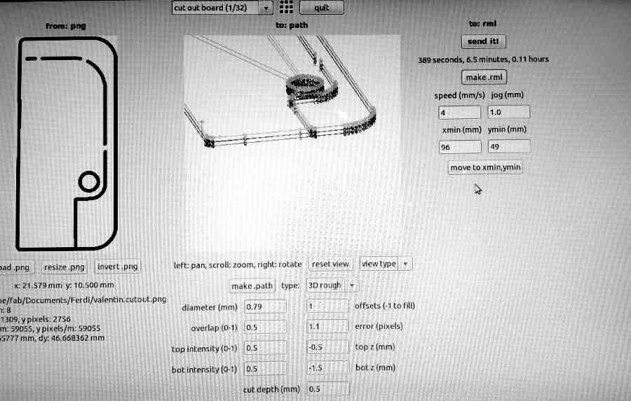
- In Fab Modules select output mode to cut
- top z = -0.5, bot z = -1.5, offset = 1.1, cut depth = 0.5
- Repeat steps 8 to 11
II. Soldering/Stuffing a PCB- I will need:
- Tweezers
- Solder iron and solder
- Good lighting
- Double-sided tape

Someone once told me you cannot truly understand something until you draw it! I find this to be true so I drew out my circuit board template.
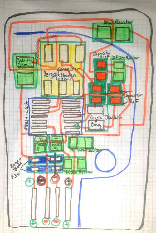
I also recommend to print out a list of components and as they are so tiny... stick them with double-sided tape to the paper, so as not lose or confuse them.
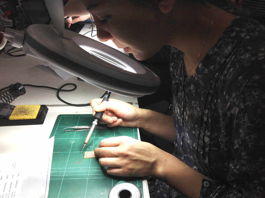
I use double-sided tape to fix the board down while soldering. I found soldering fun, I first did the small components then the larger ones.
Components for soldering include:
- Resistors- 10K Ohm (marked as 103 on resistor i.e. 10 and 10 to the power of 3), 1K Ohm, 499 Ohm (4990), two x 100 Ohm (1000), and two x 0 Ohm.
- Capacitors- 0.1 UF and two x 18 PF
- Diodes- Zener 3.3 V Orientation Important!
- One Crystal Oscillator- 20 MHZ
- One micro controller- AVR 4K Orientation Important!
- One Bergstik Header Connector for Ribbon tape- 2 x 3 Pins
After soldering the board, I encountered a short circuit problem between my micro controller and crystal oscillator. So I used a small knife to pick off the solder that caused the problem.
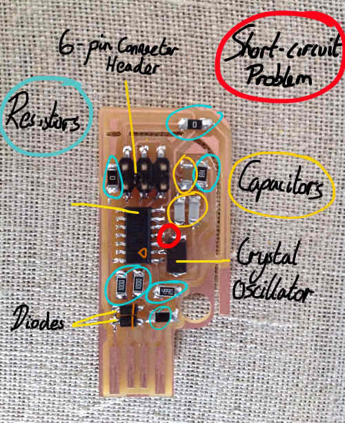
Programming a PCB- I will need:
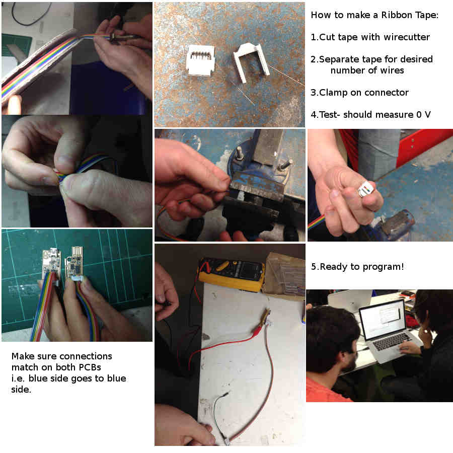
- Ribbon Tape with 6 wires
- Two USB to TTL cable
- USB to TTL cable
ribbon tape:
