Embedded Programming
PWM in C
For a basic demo of the board in C I wrote a small program that using the timer to do PWM of the LED, and the push button switch changes the duty cycle.
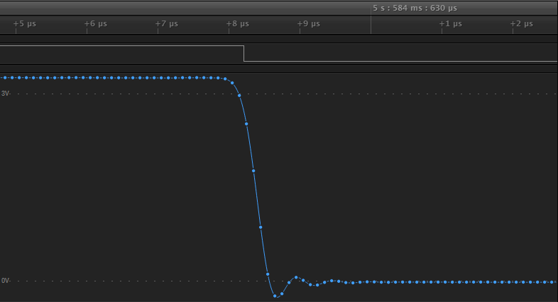
I was supprised that the push button switch didn't need debouncing, but it seems there was enough capacitance to to stop it bouncing. Since the rise/fall time was aroud 700ns.
When doing the PWM I got schooled in reading the datasheet properly and double checking flags when I couldn't figure out why I was not seeing any PWM output on OCOB. I had set the COM0B0 instead of the COM0B1 bit in the timer control register. Which is s reserved mode. Took frustratingly long to find that one.
void led_pwm_init() {
	// Disable timer interrupts
	TIMSK0 = 0x00;
	// Set Timer A for Fast PWM on OC0B
	TCCR0A = _BV(COM0B1) | _BV(WGM01) | _BV(WGM00);

	// Reset timer
	TCNT0 = 0x00;
	// Set compare value
	OCR0B = 0;

	// Set prescaler to /1024 and start pwm
	TCCR0B = _BV(CS02) | _BV(CS00);
}
I also did a fair amount of reading though the avr libc docs to see what was available. Other than a couple of neat macros like bit_is_clear/set and loop_until_bit_is_set/clear the main find was that you can use a lot of the standard c stdio functinality by defining a stdin and stdout. Below is my implementation of the software UART cribbing off neils version, though I didn't think the loop unrolling was needed.
#include "global.h"

#define uart_bit_delay 8

void uart_put_char(char output, FILE *stream);
char uart_get_char(FILE *stream);

void uart_init() {
	static FILE uart_output = FDEV_SETUP_STREAM(uart_put_char, NULL, _FDEV_SETUP_WRITE);
	static FILE uart_input = FDEV_SETUP_STREAM(NULL, uart_get_char, _FDEV_SETUP_READ);

	DDRA |= _BV(UTX_PIN);
	DDRA &= ~_BV(URX_PIN);

	// Set up stdout and stdin to use the uart
	stdout = &uart_output;
	stdin = &uart_input;
}

void uart_put_char(char output, FILE *stream) {
	cli();

	uint8_t lo = PORTA & ~_BV(UTX_PIN);
	uint8_t hi = PORTA | _BV(UTX_PIN);

	PORTA = lo;
	_delay_us(uart_bit_delay);

	for(uint8_t mask = 1; mask; mask <<= 1) {
		if (output & mask) {
			PORTA = hi;
			} else {
			PORTA = lo;
		}
		_delay_us(uart_bit_delay);
	}

	PORTA = hi;

	sei();

	_delay_us(uart_bit_delay * 2);
}

char uart_get_char(FILE *stream) {
	char output = 0x00;

	loop_until_bit_is_clear(PINA, URX_PIN);
	_delay_us(uart_bit_delay * 1.5);
	cli();
	for (uint8_t mask = 1; mask; mask <<= 1) {
		if(bit_is_set(PINA, URX_PIN)) {
			output |= mask;
		}
		_delay_us(uart_bit_delay);
	}
	sei();
	_delay_us(uart_bit_delay/2);
	return output;
}
Arduino on the ATTINY44
Using the board as an arduino was more straight forward that I though it would be. I used the arduino hardware configuration for the attiny44 from https://github.com/damellis/attiny. The way arduino does hardware definitions is quite neat, and I was supprised how simple it was to support for a different AVR microcontroller.
To test out the basic arduino funcionality I wrote a basic program that lets you toggle the led on and off using the push button switch.
static const int LED_PIN = 7;
static const int SW1_PIN = 3;

static bool led_on = false;

void setup() {
  pinMode(LED_PIN, OUTPUT);
  pinMode(SW1_PIN, INPUT);
}

void loop() {
  if(!digitalRead(SW1_PIN)) {
    led_on = !led_on;
    digitalWrite(LED_PIN, led_on ? HIGH : LOW);
    delay(50);
  }
}