Input Devices
This weeks assignment was to add a sensor to a board we designed and read from it. My final project is largely based around building a sensor platform for mountain bikes. One of the things that I want to measure is the angular velocity of the wheel. One of the ways to do that would be to use a hall effect sensor mounted to the bike fork and then a magnet attached to one of the spokes.
To get started I decided just to solder the hall effect sensor directly to a few wires and then run those to the hello world board just to get up and running and test that my strategy would work. For this I used some wire wrapping wire, which is nice and fine and easy to work with even to solder to small traces and pins. It is great for doing jump cuts and last minute bodges on boards.
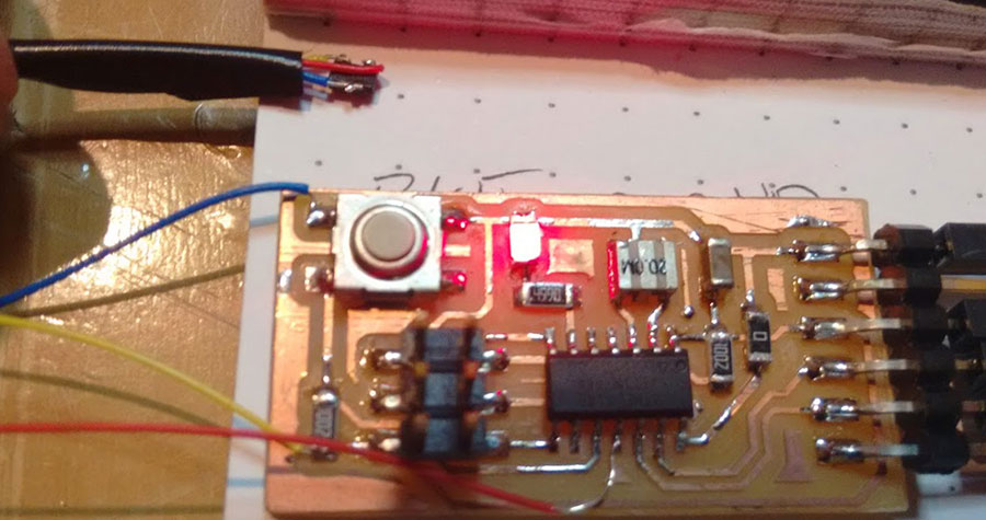
The hall effect sensor is quite sensitive and the voltage changes are very small when the a magnet is quite far away, they are also quite sensitive to orientation. Eith my rather extreme long wire setup and a 10mm diameter by 3mm high neodymium magnet I was only seeing about a 5mV change against ~2mV of background noise with the sensor 20mm away from the magnet. With a 10bit ADC reference against 5V I am only going to get about 5mV resolution. It doesn't look like it will be enough to measure the wheel rotation reliably since the magnet is going to be around 40mm from the magnet installed on the bike, maybe with signal condition and measuring it differentially instead of single ended could help.
You could make a really neat little tachometer for small motors with a hall effect sensor and a diametrically magnetized magnet.I wrote a couple of small funtions to initialize the ADC and to sample the value from the adc which I added into the my hello world board firmware.
void hall_init() {
	ADMUX = _BV(MUX1); // VCC Ref, Single ended on ADC2
	ADCSRA = _BV(ADEN) | ADC_PS_128; // enable and set prescaler
}

uint16_t hall_sample() {
	ADCSRA |= _BV(ADSC); // start conversion
	loop_until_bit_is_clear(ADCSRA, ADSC); // wait until conversion is finished
	return ADC;
}
The little python program to read the sensor value is quite neat. Since I had printf available from avr libc, I decide to just convert the value on the microcontroller side to text and send new line delimited. So instead of having to read framing bytes in pytyon I could just use the following:
value = int(ser.readline())/nsamples;
On the microcontroller side my main loop was just the following:
hall_sample_agg = 0;
for (uint8_t idx = 0; idx < SAMPLES; idx++) {
	hall_sample_agg += hall_sample();
}
printf("%lu\n", hall_sample_agg);
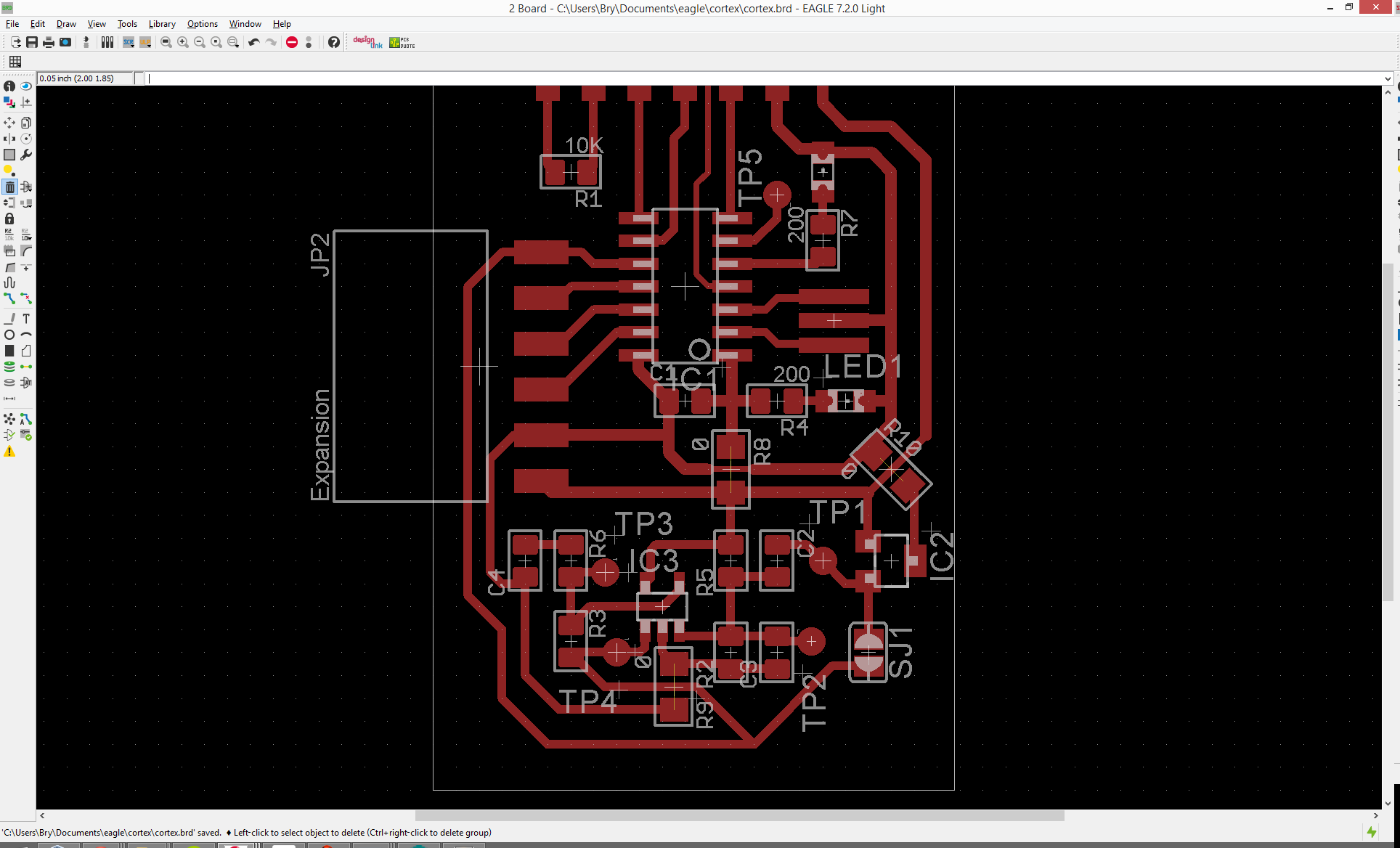
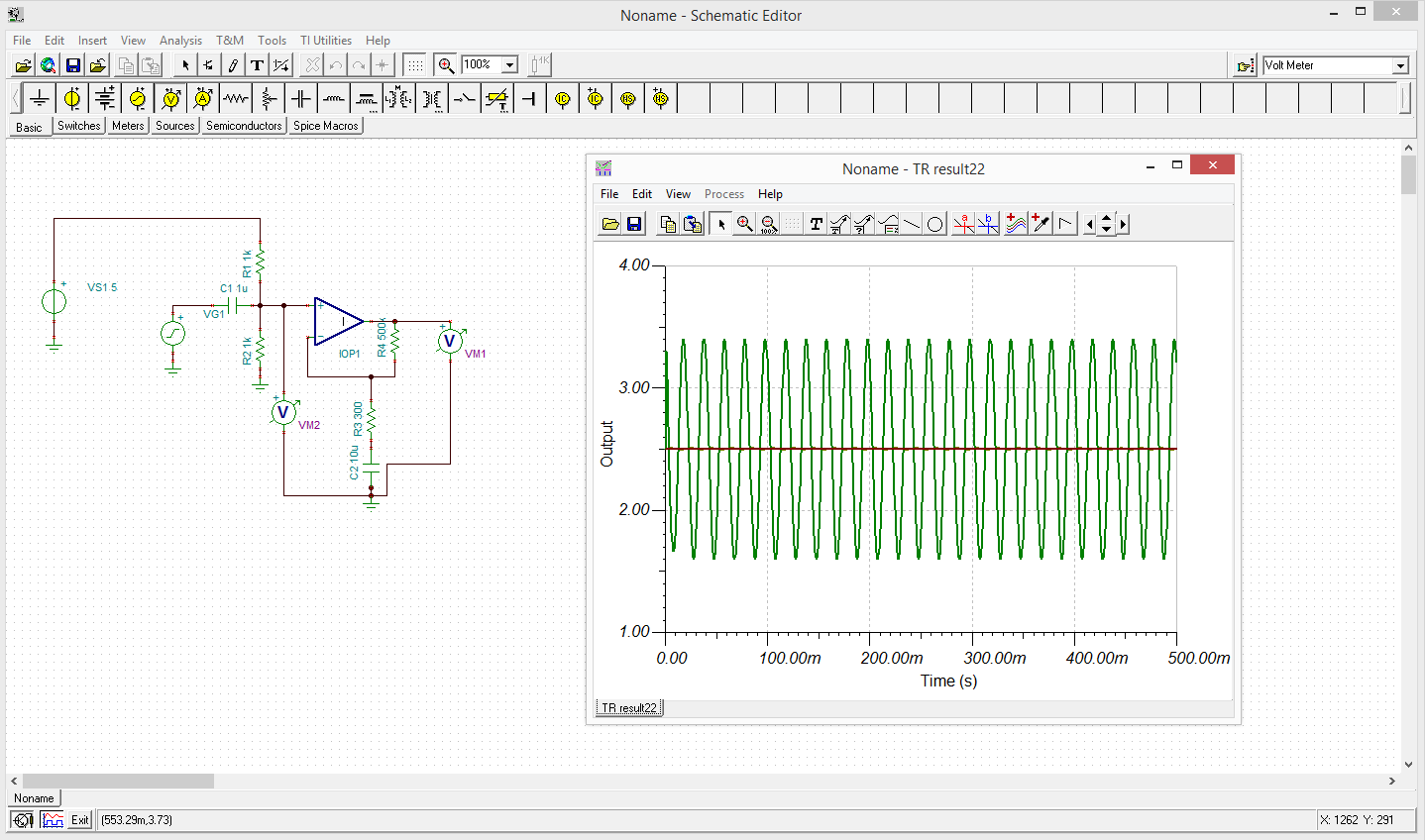
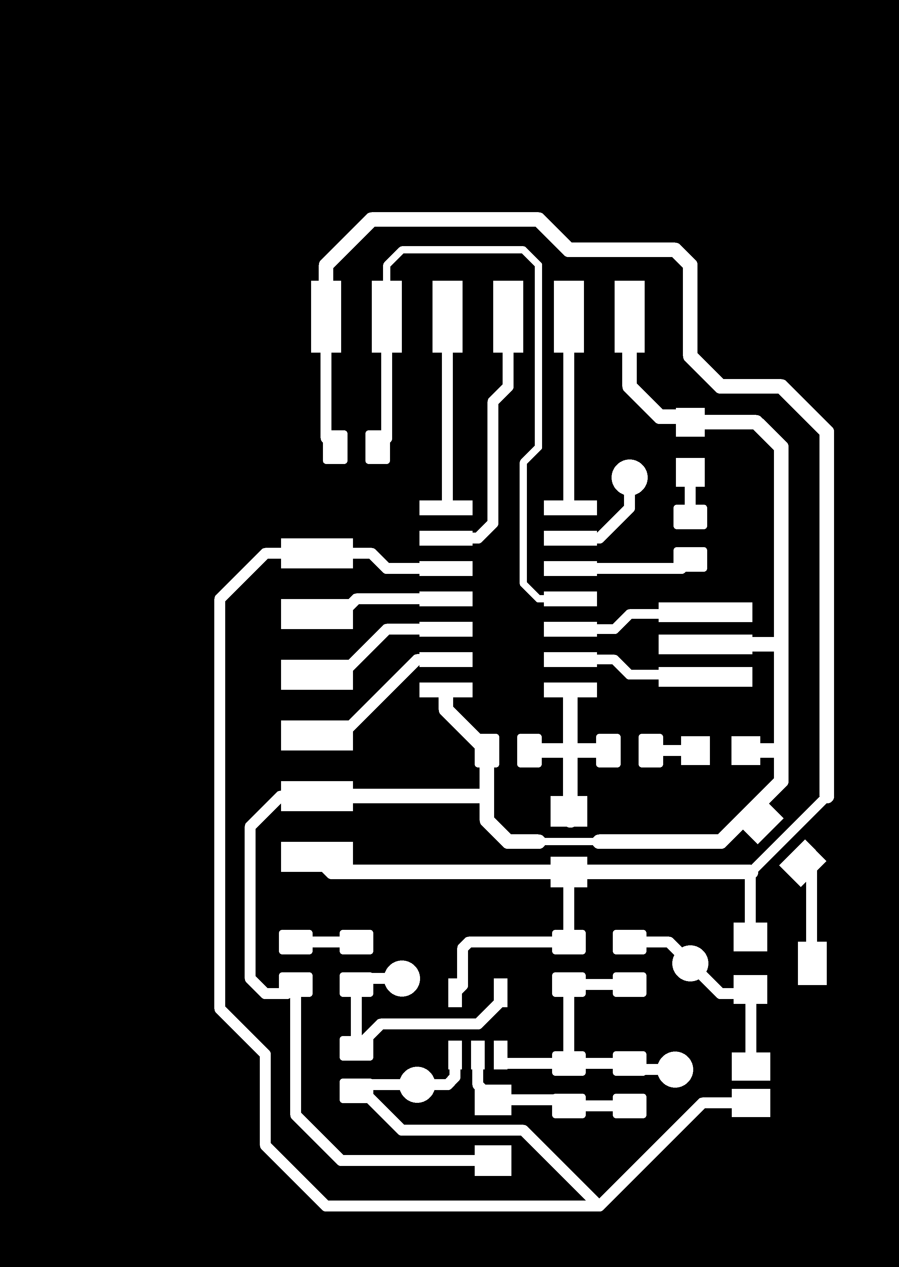
To see if it was viable to use the hall effect sensor in the way that I was thinking I created a new board in eagle. The board has the hall effect sensor and a place to put an op amp with a fairly general array of 0805 footprints to put passives to control the amplification. It is set up as an non-inverting amplifier with the ability to AC couple and bias the input, and have only amplifity AC or put a 0 ohm resisor in the place of C4 and amplify the whole signal. It might be nice to put another resistor in parallel to C4 to add a bit more flexibility to the topology. Hopefully I will get to construct the board soon and see how feasabily it is to pull such a small signal off the top of the bias voltage.

Files
Arduino Serial Bridge
The FTDI bridge I have is only 3.3V compatible. The hall effect sensor required 5V to run so I used a arduino to make a quick serial bridge with the following code. So I could run it at 5V and communicate with it.
#include <SoftwareSerial.h>

const int d_rx_pin = 10;
const int d_tx_pin = 11;

SoftwareSerial dSerial(d_rx_pin,d_tx_pin);

void setup() {
  Serial.begin(115200);
  dSerial.begin(115200);
}

void loop() {
  if(Serial.available()) {
    dSerial.write(Serial.read());
  }
  if(dSerial.available()) {
    Serial.write(dSerial.read());
  }
}