Electronics Production
This weeks task was to create the FabISP AVR in-circuit programmer. The main tasks we had to carry out to do this was to mill the circuit board, stuff the board, and load the firmware using another ICP.
To mill the circuit board I was using the Roland SRM-20. The stable version of fab modules only had support for the MDX-20, however there was a beta version published that had support for the SRM-20. Interestingly the main difference was that that have changed the units in RML-1 to be 1/100mm where as for the MDX-20 it is 1/40mm.
Using Fab modules to generate the tools paths was straight forward and takes and makes it a rather quick process to get from design to toolpaths. Even though going though a png feels weird, the end result is acceptable and it makes the pipeline easily tweakable using genric raster tools like photoshop.
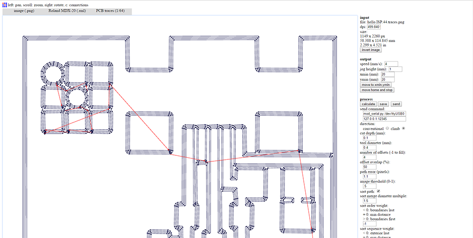
Instead of sending the toolpath directly from fabmodules I saved the generated rml files. Then I used Roland VPanel to send the file to the SRM-20. The main problem I encountered with the SRM-20 is with the Z cutting range of the spindle. At max travel it is around 40mm from the bed. Wendy pointed out that the spindles have a low and a high attachment position to change the range. However the spindle was already on its low position. I cut a couple of acrylic packers to put the FR-1 blank, which did the job, though it would have been nice to be a bit higher so the endmill didn't have to be as extended.
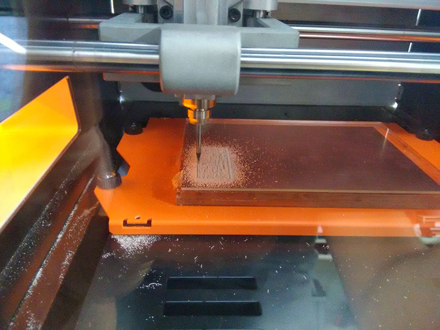
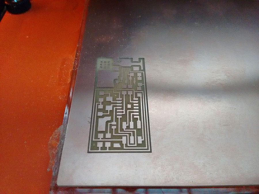
I was really impressed with how clean the FR-1 milled and how easily it cut. I have milled PCBs from FR-4 before and this was just so much smoother. I did a bit of research into the different properties of FR-1 and FR-4 and was interested to find that it can be punched and is most often used in mass production of pcb for toys and the like that don't have as much sensitivty to electrical and temperature constraints.
Populating the board was straigh forward, drag soldering of the usb connector and IC went well. Initially I was missing the zenner diodes that clamp the the USB data lines to 3.3V. As it was going to be a few days before I could get them I did a bit of reseach to see how much of an issue using 5V on the data lines would be. Turns out that most USB chipsets are rather compliant and it worked fine without them (Though I did plug it into an external usb hub just in case).
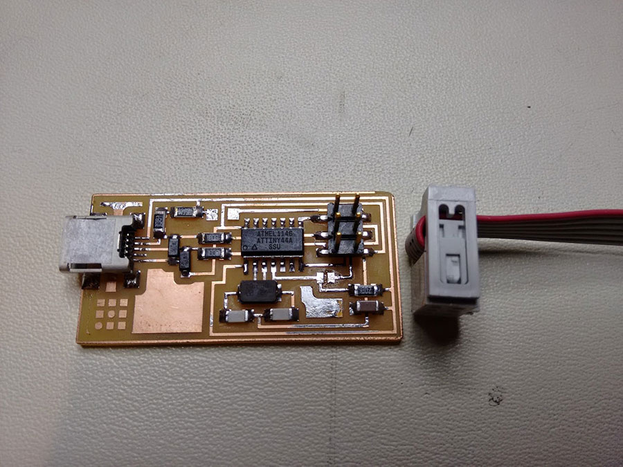
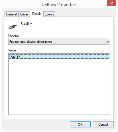
The board worked first go and I opted to build and load the firmware in linux. I plugged it into my windows box to see if it would be detected and associated with the right driver and what do you know it worked. Almost too easy.
I did like the look of one of the alternate designs that had a switch that enabled the ICP to power the target board, which I might revisit later. It would also be neat to add leds to provide feedback on the programming process and basic info like if the target board is powered as failing to power the target board seems to be the most common mistake that I make when using the programmer.